

driver side shock tower wire diagram?

Thread Starter
Junior Member
Joined: Sep 2005
Posts: 35
Likes: 0
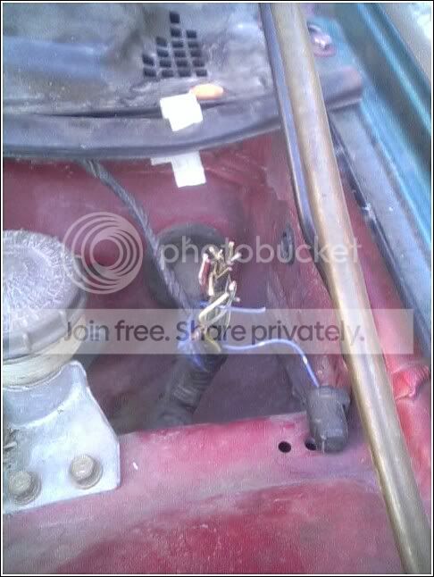
i bought a 94 civic hatch cx shell from a friend of mine, it was stolen, and the motor was stripped, then i picked it up from him. I am putting the stock cx d15b8 motor in it fornow., it is totally complete, except that the theifs cut off the connector on the driver side shock tower.
i cut off a connector on a friends parts car, and i as thinking that i can just match up the colors of the wires, so i did so, and found 2 yellow/green wires that are exactlyt he same. Does anyone have a diagram forthe shock tower coonnectors?
i cut off a connector on a friends parts car, and i as thinking that i can just match up the colors of the wires, so i did so, and found 2 yellow/green wires that are exactlyt he same. Does anyone have a diagram forthe shock tower coonnectors?
Honda-Tech Member
Joined: Oct 2002
Posts: 5,152
Likes: 24
From: chicago burbs, Il, USA
there should be only one yellow/green wire on the driver's shock tower plugs.
are you sure they are both yel/grn? there are a lot of yel/.... wires on that side.
the only yel/grn wire on the driver's side is the coolant temp sending unit signal.
(unless it was an auto trans)
.
.
.
But on the passenger's shock tower there are two.
both yel/grn wires run to the same plug. C103 (14pin connector)
there are three rows of wires, the top left should be a white/yellow wire. which will make it pin1
layout is like this from there
-01-02-03-
04-05-06-07
08-09-10-11
-12-13-14-
pin 6 is map sensor power from the ECU runs to D19 of the ECU and the yellow/green.
pin 11 is the ignition input signal to ignitor - runs from A21 & A22 of the ECU to the yellow/green wire at the distributor.
BTW I don't have a diagram, I'm peicing this info together from the Helm manual.
Trending Topics

Thread
Thread Starter
Forum
Replies
Last Post