

MPFI Q


Thread Starter
Honda-Tech Member
Joined: May 2004
Posts: 955
Likes: 0
From: Don't Jack Me, Ca
Okay, C1/C2 were moved to B10/B12. I put B2/B11 where C1/C2 USED to go. A3/A7 Are for injectors 2/4. Is the old C1/C2[Now in B10/B12] going to be used for the Dizzy wiring. If so, where are B2/B11 going to be going to? Or are they simply unused now? TIA peeps.
Honda-Tech Member
Joined: Nov 2004
Posts: 118
Likes: 0
From: Virginia Beach, Virginia, USA
http://tech.hybridgarage.com/t...g.htm
Wires where C1 and C2 were should now go to the cylinder position sensor on the dizzy. B2 and B11 should now be unused. Did you have wires at B2 and B11? They should have been empty. It says unused pins can be taken from there.
Wires where C1 and C2 were should now go to the cylinder position sensor on the dizzy. B2 and B11 should now be unused. Did you have wires at B2 and B11? They should have been empty. It says unused pins can be taken from there.
Thread Starter
Honda-Tech Member
Joined: May 2004
Posts: 955
Likes: 0
From: Don't Jack Me, Ca
I had wires at b2/b11 but the car was never an Automatic nor does it have an FITV so im fine with cutting those. But I did put them on the C plug where 1/2 are. This is after I removed the original C1/C2 and placed them into the B plug at 10 and 12. So I never really needed to move B2/B11 to old C1/C2, I was just not understanding the instructions. So the C1/C2 now at B10/B12 will be wired directly to my dizzy, thus making the old 5 wire + C1/C2 wires a 7 wire clip. That part makes sense. So only 4 wires will be leaving the ECU and going into the engine bay. And then I've got the injector/resistor box wiring right I believe. The old 2 power wires from the old DPFI injectors need to be put together and made into 1 single wire, which will feed power to the resistor box. I hope I got it. TY for the fast reply JKingCivicSi
Honda-Tech Member
Joined: Nov 2004
Posts: 118
Likes: 0
From: Virginia Beach, Virginia, USA
<TABLE WIDTH="90%" CELLSPACING=0 CELLPADDING=0 ALIGN=CENTER><TR><TD>Quote, originally posted by DOHCZCCRXSi »</TD></TR><TR><TD CLASS="quote">So the C1/C2 now at B10/B12 will be wired directly to my dizzy,</TD></TR></TABLE>Not exactly. The orange and white wires that used to be at C1 and C2 now go to the B10 and B12 pin in the plug. Wires from the C1 and C2 pins go to the dizzy.
Thread Starter
Honda-Tech Member
Joined: May 2004
Posts: 955
Likes: 0
From: Don't Jack Me, Ca

This is how my car is wired at the moment. I know its wrong, the car is spewing gas like its going out of style. So the injectors are all correctly wired, but the dizzy is not sparking. It has to do with my wiring, but for some reason none of the instructions I've read make sense to me. I don't know if they want me switching/cutting/moving; because as stated above I can't wire to save my life. Someone please shed some light on this for me so I can drive my new snatchback! You guys rock,

Trending Topics
Joined: Apr 2005
Posts: 389
Likes: 0
From: Cowley, Wy, 82420
no wait i lied again the wires you cut from c1 and c2 go to b10 and b12 c1 to b10 and c2 to b12 and then the wires you extend from c1 and c2 into the engine compartment go to the crank angle sensor which are the 2 unused pins on the new SI dizzy
Thread Starter
Honda-Tech Member
Joined: May 2004
Posts: 955
Likes: 0
From: Don't Jack Me, Ca
God I suck at life. I'm just gonna unplug the internet line and hang myself with it, but first ill piece this ******* car out. So the 2 wires I put at B10/B12 need to go straight to my Crank Angle Sensor. And C1/C2 need to go to the dizzy wires[the blue/green blue/yellow]. So what about the orange/white wires that were at C1/C2, are they now unused like the A7/A3 wires?
Joined: Apr 2005
Posts: 389
Likes: 0
From: Cowley, Wy, 82420
okay on the ecu
a3 and a7 to go the injectors.
you cut wires from c1 and c2 and move c1 to b10 and c2 to b12.
and then you extence wires into the engine compartment from c1 and c2 and those go to the unused pins on the new SI dizzy and c1 goes to the blue/green wire and c2 goes to the blue/yellow wire
a3 and a7 to go the injectors.
you cut wires from c1 and c2 and move c1 to b10 and c2 to b12.
and then you extence wires into the engine compartment from c1 and c2 and those go to the unused pins on the new SI dizzy and c1 goes to the blue/green wire and c2 goes to the blue/yellow wire


Thread Starter
Honda-Tech Member
Joined: May 2004
Posts: 955
Likes: 0
From: Don't Jack Me, Ca
Skinflute, [BOLD]YOU ... DA ... ******* ... MAN![/BOLD] God, its too late to go to the house the cars at to try it, but I set the alarm for 6. I'm still purplexed as to why the ECU is only throwing code 6[engine coolant temp sensor]. Because I have like no sensors hooked up. For a while it threw code 8, but after playing with the 2 white wires on the dizzy, it went away. Thx again
Thread Starter
Honda-Tech Member
Joined: May 2004
Posts: 955
Likes: 0
From: Don't Jack Me, Ca
Okay, tried it. The car turned a few times then it felt as if a piston was hitting a valve. I pulled the plugs and tried to fire and lo and behold literally 6 oz of gas was shot @ my face. The problem is it was only on cylinder 3. Still on recieving code 6. And I can hear the fuel pump squeezing gas into the rail, almost like the injectors are continuously pulling fuel. Pulling the power wire off the resistor box only made a slight click, but the noise was still present. Why would only 1 cylinder be flooding like this? The other 3 plugs are wet also, just not saturated like this one. Could it be I've got the wrong primary wires from the old DPFI wires wrong? The power[not primary] 2 wires[1 of each injector] from the old DPFI harness were soldered together then extended to the resistor box.
Thread Starter
Honda-Tech Member
Joined: May 2004
Posts: 955
Likes: 0
From: Don't Jack Me, Ca
I'm gonna go buy a huge loom of wire and just simpley run straight from the ECU to each wires corresponding position if this doesn't work soon.
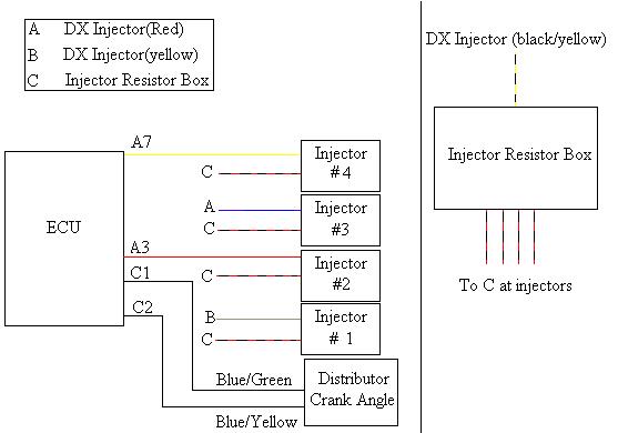
C1 = Blue/Green wire on the dizzy harness
C2 = Blue/Yellow wire on the dizzy harness
B10 = Orange[used to be connected to C1]
B12 = White [used to be connected to C2]
A3 = Straight to #2 injector[which is Red]
A7 = Straight to #4 injector[which is Yellow]
On my old DX harness, the 2 injector plugs should have had 2 wires on each.
One of them being Red as the Primary, and a Yellow/Black being the Power wire.
The second being Yellow as the Primary, and a Yellow/Black being the Power wire.
The Red DPFI wire should be extended to reach the #3 injector.
The Yellow DPFI wire should be extended to reach the #1 injector.
And A15 is going to be taken straight from the ECU and extended to the Resistor Box Power wire.
^ This should be EXACTLY what I need to get fuel/spark.