

Intercooler end tank designs (Solidworks approach)

Thread Starter
Honda-Tech Member
Joined: Mar 2006
Posts: 428
Likes: 0
From: NH, usa
This thread started earlier in the welding/fabrication forum, but due to it not being related to that topic I decided to move the topic here since this section of the forum is quite familiar with intercoolers and what works best.
Here's a little something I did at 15 psi with 2 psi loss through the exit. Turbulence of the inlet is so bad that air doesn't even flow through all the tubes. Air shows huge velocity drops, and is not the same through all the tubes. This will prove to be worse with the inlet/exit tubes placed more towards the bottom end of the intercooler.


Later I put fins inside the end tanks to help flow.

The fancier fences perform better as I thought. The air is spread out more evenly and has a higher velocity then the bottom half of this intercooler design. Both fins seem to be an improvement over the one without fins. I can now go over and fix some of the fins for maximum flow, but by this point I think we all get the point and I would like to move on to another design. If you have exact measurements and pix, I can test something else.

Here's a little something I did at 15 psi with 2 psi loss through the exit. Turbulence of the inlet is so bad that air doesn't even flow through all the tubes. Air shows huge velocity drops, and is not the same through all the tubes. This will prove to be worse with the inlet/exit tubes placed more towards the bottom end of the intercooler.
Later I put fins inside the end tanks to help flow.
The fancier fences perform better as I thought. The air is spread out more evenly and has a higher velocity then the bottom half of this intercooler design. Both fins seem to be an improvement over the one without fins. I can now go over and fix some of the fins for maximum flow, but by this point I think we all get the point and I would like to move on to another design. If you have exact measurements and pix, I can test something else.
Thread Starter
Honda-Tech Member
Joined: Mar 2006
Posts: 428
Likes: 0
From: NH, usa
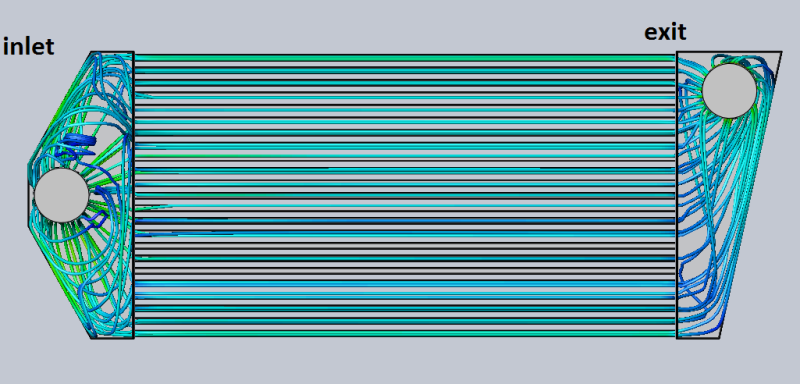
Next is this 14" by 26" core with 9" long end tanks. 15 psi with only 1 psi loss. It also features more accurately sized tubes.


An improvement over the top end tanks.
An improvement over the top end tanks.
Last edited by AWOC; Dec 25, 2009 at 07:10 PM.
Thread Starter
Honda-Tech Member
Joined: Mar 2006
Posts: 428
Likes: 0
From: NH, usa
What did you have in mind?? Just remember any adjustment to the intercooler will only reflect changes for a certain psi, but with a constant psi pass which what the intercooler will see most for a race car or wot, I assumed a constant 15 psi to see where improvements can be to squeeze some more hp. Variable intake change is difficult to design for since the boundary conditions are changing rapidly. Setting boundaries in SD is kinda tricky and I need exact timing and pressure. Looking at the intercooler at set constant psi range I think is a better tool.
Suspetise...
Joined: Nov 2002
Posts: 12,287
Likes: 1
From: Burninating the peasants yo
I like it! In for more designs, and also interested in how the backdoor variety stacks up.
Also, in the finned design, am I looking at the flow diagram correctly in assuming that the curved fins seem to be more efficient than the straight/bent fins?
Also, in the finned design, am I looking at the flow diagram correctly in assuming that the curved fins seem to be more efficient than the straight/bent fins?
Trending Topics
Thread Starter
Honda-Tech Member
Joined: Mar 2006
Posts: 428
Likes: 0
From: NH, usa
yes the curved worked better. If you look at the top half compared to the bottom half there is more flow and a faster velocity. For the backdoor style I need to know which style end tank, so if can send me a link for visuals I will get cranking on it.
Thread Starter
Honda-Tech Member
Joined: Mar 2006
Posts: 428
Likes: 0
From: NH, usa
I was skeptical over the back door design that I came up with, but I thought wrong. This design seems to be the best one so far. There is a big improvement on the spread of air to all the tubes of the intercooler. The entry end tank seems to have some turbulence from the air hitting the wall of the end tank and slowing the air velocity, but a little curving and I think this intercooler could be a good design.


Last edited by AWOC; Dec 26, 2009 at 08:24 AM.
If you realy think about it. A stright shot in like a normal intercooler the air hits the center and can not flow the air so it reverses its flow and creates turbulance for the rest of the cross fins.
In a back door setup with a curved front wall the air hits the wall and spreads down the wall undensing the air and spreads it more evenly over the cross fins.
I dunno if this made sense?
In a back door setup with a curved front wall the air hits the wall and spreads down the wall undensing the air and spreads it more evenly over the cross fins.
I dunno if this made sense?
Honda-Tech Member

Joined: Jan 2004
Posts: 127
Likes: 0
From: Columbus, Ohio, USA
Very cool! Anyone know where I can find more information on this program? I imagine it's pretty pricey?
Just a thought: What if you were to design more aerodynamic transitions into each tube in the core? I.E. weld in a triangular shaped strip the depth of the core in between each tube inside the endtank. My line of thinking is that air would flow easier into the tubes with encouragement versus hitting a flat area between each tube.
This shouldn't help equally disperse the air through the core, but it might help keep the velocity up.
Last edited by Tulo; Dec 26, 2009 at 09:19 AM.
Honda-Tech Member
Joined: Jan 2004
Posts: 127
Likes: 0
From: Columbus, Ohio, USA
On a side note, I imagine this has got to be an extremely efficient end-tank design. It is a custom T1 piece made for 'kutsujus2k's' s2000.


HELLO,GOOD MORNIN'
Joined: Sep 2002
Posts: 8,909
Likes: 0
From: Savin lives
yep that's exactly why the T1 intercooler works really well. Anything with a slight curve on a back door tank would be better than air hitting a flat wall. I have a friend that made a 600hp IC into a back door and once he got to 620 it kept him from making more power also because the IC was being maxed out.
good data. I want to send you one but i have an idea of what it will do.
good data. I want to send you one but i have an idea of what it will do.
Honda-Tech Member
Joined: May 2008
Posts: 39
Likes: 0
General rule of thumb for your dividers, keep the angle between dividers less than ~13-15 degrees to avoid backflow.

Thread Starter
Honda-Tech Member
Joined: Mar 2006
Posts: 428
Likes: 0
From: NH, usa
You're misinterpreting the results. The reason why the air has a higher velocity on the curved fin section is because you've decreased the cross section between fins. Look at the flow bath between the 3rd and 4th curve fin... you've created a nozzle there. You can actually examine this area on the results and you can see the increased velocity at this minimal area. The job of the end tank is to successfully DECREASE velocity and distribute the airflow without recirculation/separation.
General rule of thumb for your dividers, keep the angle between dividers less than ~13-15 degrees to avoid backflow.
General rule of thumb for your dividers, keep the angle between dividers less than ~13-15 degrees to avoid backflow.
BTW.. the rule of thumb on diverging areas is 5-15 degrees. This allows for minimum boundary layer separation, but this is all depended on air velocity. The higher the velocity the less separation. Smaller air velocities require the smaller diverging angles, due to the lack/loss of energy to keep the boundry layer fully developed. For this application this rule of thumb goes out the window===> 1) because at these angles the end tanks would be too long for most cars 2) The air velocity is high enough to keep flow fully developed. Keep in mind that I'm only trying to maximize high boost applications 15psi-up.
That T1 intercooler looks pretty good. Do you have exact measurements? I would like to run that one.
Honda-Tech Member
Joined: Jul 2002
Posts: 1,364
Likes: 1
From: Port Arthur, TX, USA
I think it's good to have the velocity moving at a somewhat constant velocity through all fins of the intercooler, otherwise you aren't using it to it's capacity. Just be sure that whatever design you use isn't something that will cause a great pressure drop and cause a lot less flow. A good design to remove lots of heat from the air will most probably also be good to cause a pressure drop. Be sure to factor this into the overall design of the system.
Thread Starter
Honda-Tech Member
Joined: Mar 2006
Posts: 428
Likes: 0
From: NH, usa
I think it's good to have the velocity moving at a somewhat constant velocity through all fins of the intercooler, otherwise you aren't using it to it's capacity. Just be sure that whatever design you use isn't something that will cause a great pressure drop and cause a lot less flow. A good design to remove lots of heat from the air will most probably also be good to cause a pressure drop. Be sure to factor this into the overall design of the system.
Last edited by AWOC; Dec 26, 2009 at 07:24 PM.
Honda-Tech Member
Joined: May 2008
Posts: 39
Likes: 0
No I think you are! The increased velocity will help the boundary layers of flow and create less separation. Less separation means that turbulence will not cause distribution problems, and that velocity is kept high. Decreasing velocity will effect head loss in in the system, so you want to minimize this with the best spread possible. Too much of a decrease in velocity causes high pressure fields in the intercooler, which would cause back flow in the entry section. By speeding up air in the entry, I caused the fluid to speed up and as you can see the colors in the top section of the finned intercooler you will see that flow is faster and a a better spread. An overall improvement over the non-finned one, but just a test cause I never went back and improved on the design so thats why you see separation.
BTW.. the rule of thumb on diverging areas is 5-15 degrees. This allows for minimum boundary layer separation, but this is all depended on air velocity. The higher the velocity the less separation. Smaller air velocities require the smaller diverging angles, due to the lack/loss of energy to keep the boundry layer fully developed. For this application this rule of thumb goes out the window===> 1) because at these angles the end tanks would be too long for most cars 2) The air velocity is high enough to keep flow fully developed. Keep in mind that I'm only trying to maximize high boost applications 15psi-up.
That T1 intercooler looks pretty good. Do you have exact measurements? I would like to run that one.
As for increased velocity delaying seperation, I would disagree there. Additional transverse fluidic energy will delay separation and generally increased turbulence will delay separation, however this is true at a constant Reynolds number. If your means of inducing turbulence is increasing the Reynolds number, you've increased the ratio of fluid inertia to viscosity. Since air is nearly inviscous, you'll inevitably increase separation by increasing velocity as you're decreasing the effects of viscosity and viscosity is needed to change the velocity profile without separation. Generally, higher Reynold's number flows are less sensitive to changes in area, they just plow right through.
On wind turbine and aircraft blades, we employ vortex generators to create multiple counter-rotating vortices to increase the normal component of velocity in the boundary layer to decrease separation, but again, at a constant Reynolds number...
Can I ask what your background is? What sort of field do you work in?
Honda-Tech Member
Joined: Jan 2004
Posts: 127
Likes: 0
From: Columbus, Ohio, USA
The endtanks are custom, you would have to contact Mr. Palo for those specs.
Thread Starter
Honda-Tech Member
Joined: Mar 2006
Posts: 428
Likes: 0
From: NH, usa
As for increased velocity delaying seperation, I would disagree there. Additional transverse fluidic energy will delay separation and generally increased turbulence will delay separation, however this is true at a constant Reynolds number. If your means of inducing turbulence is increasing the Reynolds number, you've increased the ratio of fluid inertia to viscosity. Since air is nearly inviscous, you'll inevitably increase separation by increasing velocity as you're decreasing the effects of viscosity and viscosity is needed to change the velocity profile without separation. Generally, higher Reynold's number flows are less sensitive to changes in area, they just plow right through.
On wind turbine and aircraft blades, we employ vortex generators to create multiple counter-rotating vortices to increase the normal component of velocity in the boundary layer to decrease separation, but again, at a constant Reynolds number...
Can I ask what your background is? What sort of field do you work in?
Honda-Tech Member
Joined: Jul 2002
Posts: 1,364
Likes: 1
From: Port Arthur, TX, USA
see the problem is that you mechanical engineers overanalyze everything and use too many big words lol
remember a good engineer gets the job done at a low cost haha
remember a good engineer gets the job done at a low cost haha
Honda-Tech Member
Joined: May 2009
Posts: 184
Likes: 1
From: Kamloops, B.C. Canada
If you look at a lot of OEM intercooler end-tank setups, I think you'll see that most are backdoor designs. Even all of the big stinky diesel Pickups i have to work on are backdoor intercooled. I can totally believe that backdoor setups would be superior.
