
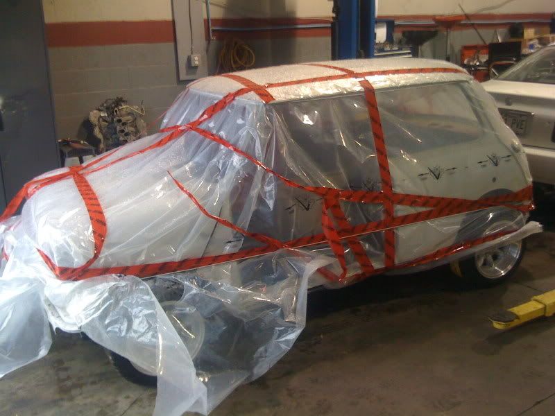
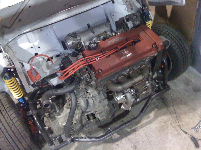
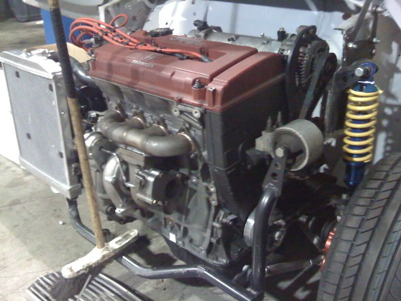
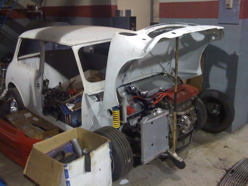
recent pics at work, typeR in a mini, with a gt2871r intercooled
 12-03-2008, 07:14 PM
#1
Honda-Tech Member
Thread Starter
Join Date: Jan 2005
Posts: 67
Likes: 0
Received 0 Likes
on
0 Posts
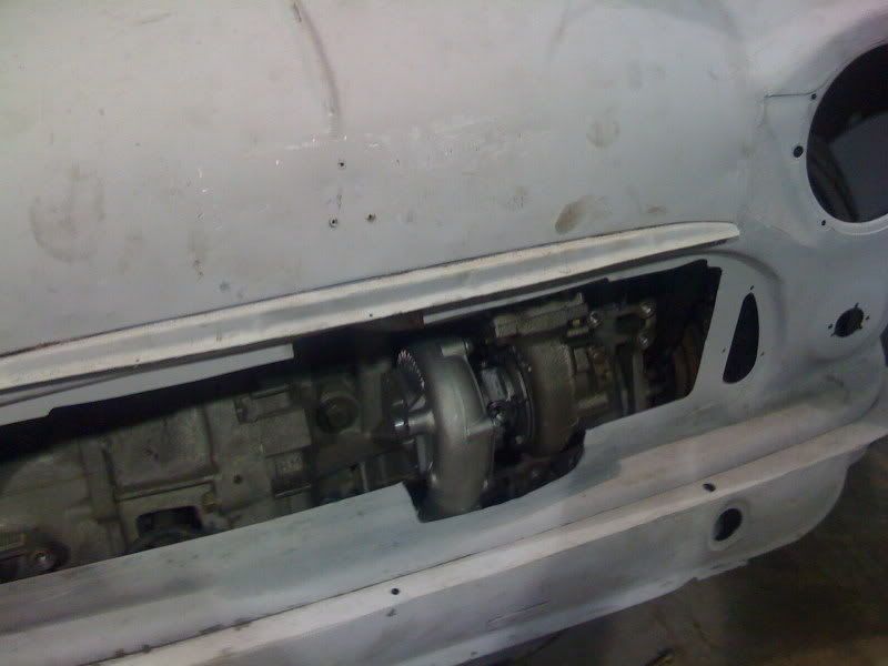
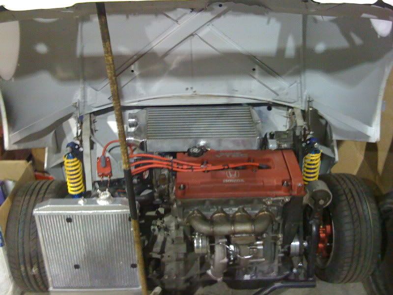
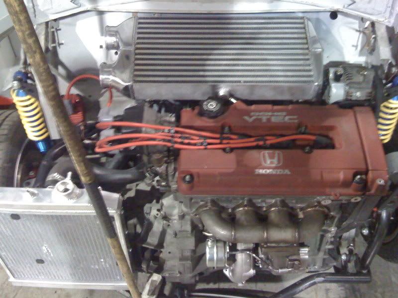
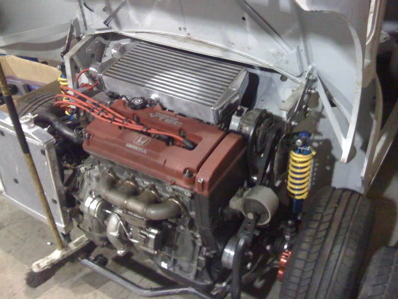
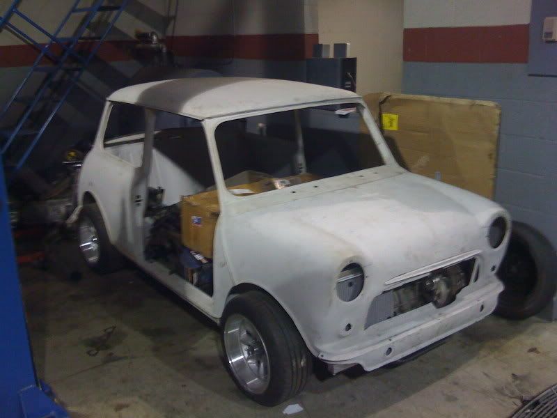
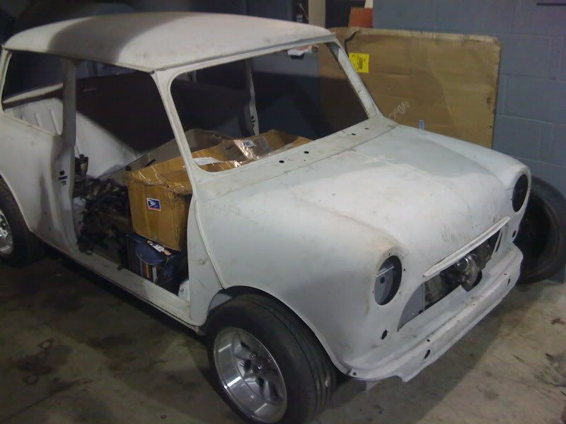
im currently building a mini austin. ill let the pics talk for themselves, obviously the room is very tight, and the car is not done yet, some ideas may change, but basicly this is the setup! the car was not extended, its all original in size.
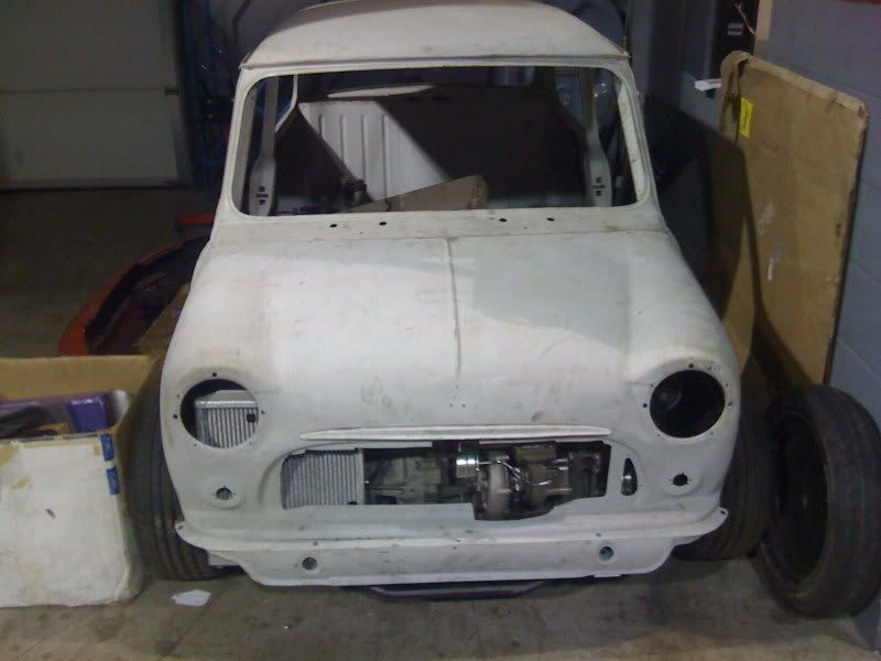
everything fits realy tight, and there is les than half an inch of room in front of the turbo and the grill.
i saw a few of these builds on youtube. should be fun to see what it does when its all done.
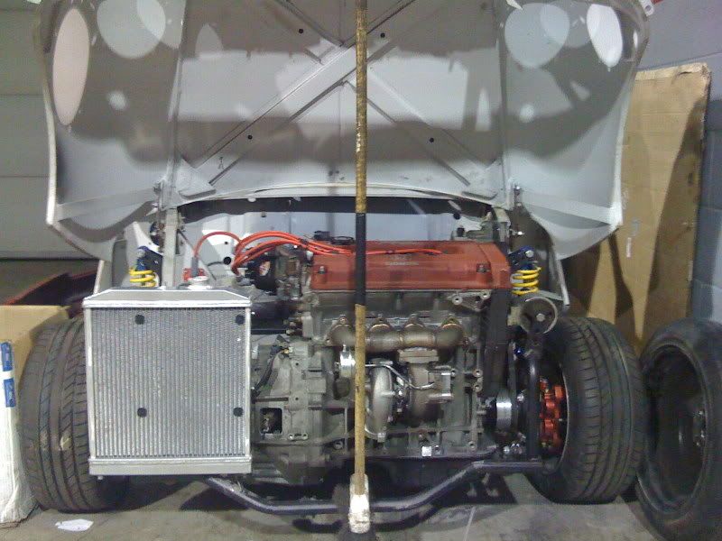
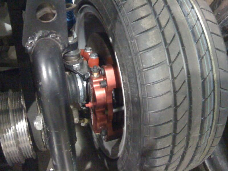
btw, the front clip is made by a company i believe the name is superfastmini.com came with the big brakes, axles, coilovers, ect. things didnt fit as easy as it looks, but over all a fun kit to work with!
now for the pics
everything fits realy tight, and there is les than half an inch of room in front of the turbo and the grill.
i saw a few of these builds on youtube. should be fun to see what it does when its all done.
btw, the front clip is made by a company i believe the name is superfastmini.com came with the big brakes, axles, coilovers, ect. things didnt fit as easy as it looks, but over all a fun kit to work with!
now for the pics

 12-03-2008, 10:13 PM
#6
Honda-Tech Member
Thread Starter
Join Date: Jan 2005
Posts: 67
Likes: 0
Received 0 Likes
on
0 Posts
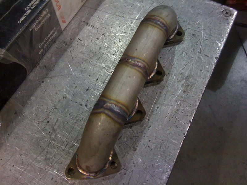
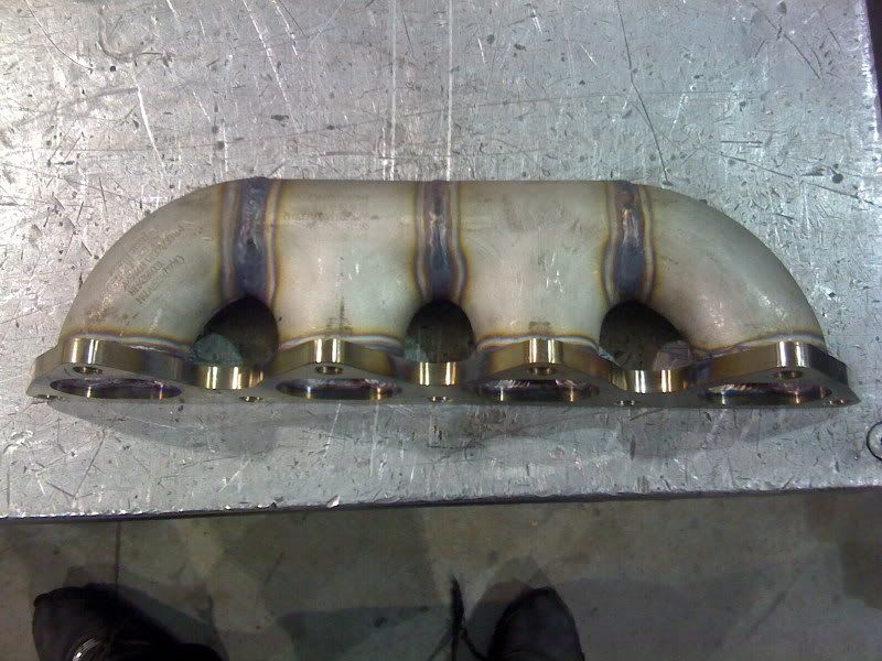
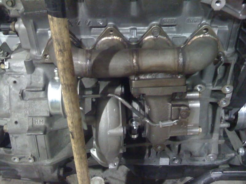
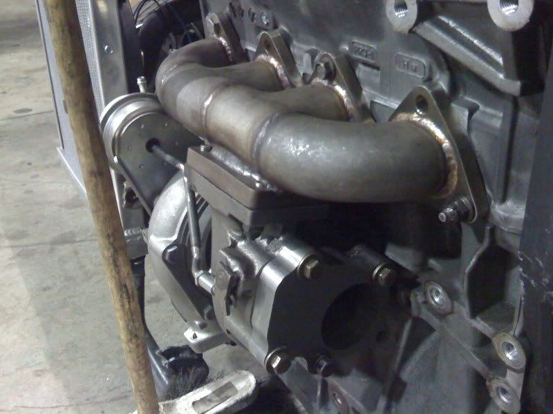
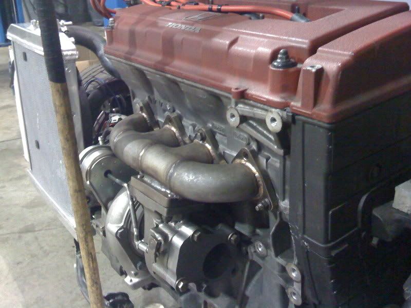
I would have loved to make a manifold with better flow than a log style, but space was a huge issue. I have less than an inch clearence in front and on top of the manifold once the hood is closed, it's amazing it even fit
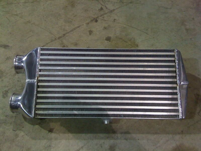
And for the end tank I assume your talking about the intercoolers loop side, I hope it won't be an issue, but I don't think so because the core is 3 " so it's wider than the 2.5" out, I hope that makes sence, but wtv LOL
And for the end tank I assume your talking about the intercoolers loop side, I hope it won't be an issue, but I don't think so because the core is 3 " so it's wider than the 2.5" out, I hope that makes sence, but wtv LOL
12-04-2008, 05:24 AM
#7
Honda-Tech Member
Join Date: Aug 2004
Location: IA, US
Posts: 569
Likes: 0
Received 0 Likes
on
0 Posts
Looks like a really fun build!!
I'm a little skeptical that this engine mount bracket is going to hold up due to both the bracket size itself and the welding/tube wall thickness?/lack of gusset/missing front mount. But I may be overestimating the forces being put on the mount.
Good luck!
Trending Topics
12-04-2008, 05:39 AM
#8
I've seen a bunch of these builds before and they look like a ****ing blast to drive. I think thats the first I've ever seen with the taller block though, I've only ever seen them with b16s
12-04-2008, 07:40 AM
#10
Solbros Owns Me
Looks like a really fun build!!
I'm a little skeptical that this engine mount bracket is going to hold up due to both the bracket size itself and the welding/tube wall thickness?/lack of gusset/missing front mount. But I may be overestimating the forces being put on the mount.
Good luck!
I'm a little skeptical that this engine mount bracket is going to hold up due to both the bracket size itself and the welding/tube wall thickness?/lack of gusset/missing front mount. But I may be overestimating the forces being put on the mount.
Good luck!
That mount will be fine. The torque of the engine is mostly transmitted through the rear mount, and the uppers are primarily for support.
12-04-2008, 07:47 AM
#11
Honda-Tech Member
Join Date: Aug 2004
Location: IA, US
Posts: 569
Likes: 0
Received 0 Likes
on
0 Posts
I think I may have added a few unnnecessary tubes in my last crx 8-point cage
 12-04-2008, 10:40 AM
#14
Honda-Tech Member
Join Date: Apr 2003
Location: Montreal, Quebec, Canada
Posts: 988
Likes: 0
Received 0 Likes
on
0 Posts
Hey, work looks good! Is MTLMotorsport a new shop in the MTL area? Never heard of it before.
Good work! A turbo type-r must be sick in a little car like that!
Good work! A turbo type-r must be sick in a little car like that!
12-04-2008, 06:04 PM
#16
Honda-Tech Member
Thread Starter
Join Date: Jan 2005
Posts: 67
Likes: 0
Received 0 Likes
on
0 Posts
but i do co-own the shop and its called tdc motorsport. were mainly in the honda/nissan croud, and we run the "dmcc" kumho drift team in montreal.
btw, thanks for the replies guys! im gonna put some more work into it monday, should have some more pics soon.
12-04-2008, 07:27 PM
#20
Junior Member
Join Date: Oct 2008
Location: Washington
Posts: 75
Likes: 0
Received 0 Likes
on
0 Posts
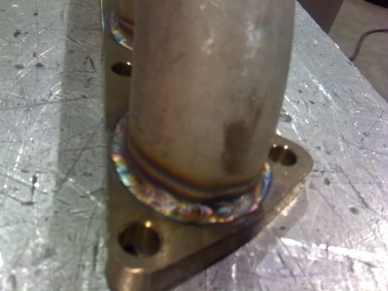
given you some props on your beads man. very nice. im a welder/fabricater myself!
also, thats awesome you dropped that whole set up on the copper, that thing will rip like no other!!!
thanks, Casey
also, thats awesome you dropped that whole set up on the copper, that thing will rip like no other!!!
thanks, Casey
12-05-2008, 04:58 AM
#21
Honda-Tech Member
Join Date: Jun 2002
Location: Brooklyn, NY
Posts: 645
Likes: 0
Received 0 Likes
on
0 Posts
Now thats what I'm talking about!!! I've seen so many builds with the "B" series motor but none turbocharged. I was hoping to do the same but could'nt find a shell for a decent price.
More here
More here
12-05-2008, 05:31 AM
#22
Honda-Tech Member
Join Date: Aug 2004
Location: IA, US
Posts: 569
Likes: 0
Received 0 Likes
on
0 Posts
I would have loved to make a manifold with better flow than a log style, but space was a huge issue. I have less than an inch clearence in front and on top of the manifold once the hood is closed, it's amazing it even fit
And for the end tank I assume your talking about the intercoolers loop side, I hope it won't be an issue, but I don't think so because the core is 3 " so it's wider than the 2.5" out, I hope that makes sence, but wtv LOL
And for the end tank I assume your talking about the intercoolers loop side, I hope it won't be an issue, but I don't think so because the core is 3 " so it's wider than the 2.5" out, I hope that makes sence, but wtv LOL
Here is a decent document with some fluid dynamic concepts applied to intercooler design:
http://www.dvdtfab.com/intercoolertestlab.pdf
I've also attached a image of what the flow might look like through design similar to yours.
Last edited by Andy R; 12-05-2008 at 05:53 AM.
12-05-2008, 07:40 AM
#23
Honda-Tech Member
Thread Starter
Join Date: Jan 2005
Posts: 67
Likes: 0
Received 0 Likes
on
0 Posts
The intercooler design is not ideal, but the inefficiencies may be acceptable to you for this project. Running the air back through the core is effectively give you a longer, but skinnier core. This can help make it easier to evenly distribute air across the core because you have fewer rows to spread out from a 2.5" inlet, but with the added pressure loss and the loss associated with the TIGHT 180 degree turn at the far end endtank. If your stuck with the dual pass approach due to space constraints, you could improve upon this design be making the inlet and outlet tubes meet the end tank with a radius rather than the abrupt angle change where eddies can form. Also, the far side end tank could be larger to allow a more gradual 180 curve and some guide vaines to help evenly distribute the air around that corner.
Here is a decent document with some fluid dynamic concepts applied to intercooler design:
http://www.dvdtfab.com/intercoolertestlab.pdf
I've also attached a image of what the flow might look like through design similar to yours.
Here is a decent document with some fluid dynamic concepts applied to intercooler design:
http://www.dvdtfab.com/intercoolertestlab.pdf
I've also attached a image of what the flow might look like through design similar to yours.
btw, thanks again for all the posts
12-05-2008, 07:44 AM
#24
Honda-Tech Member
Thread Starter
Join Date: Jan 2005
Posts: 67
Likes: 0
Received 0 Likes
on
0 Posts
i heared of that car, if im correct, one of my friends did some work on that car,... Tom from tk-racehaeds. i think he worked on the busa motor, or maybe im wrong, but he talks about him often.
12-05-2008, 11:54 AM
#25
Honda-Tech Member
Join Date: Aug 2004
Location: IA, US
Posts: 569
Likes: 0
Received 0 Likes
on
0 Posts
thanks man, very interesting stuff, i think im gonna try to make an intercooler with curved plates in the loop side the next time i do a cooler like this. should be nice to see, and maybe ill do a swap on the dyno with a k20 setup i have in mid to see acual power differences. ill pm you when i do it.
btw, thanks again for all the posts
btw, thanks again for all the posts
Here are a few pics of the IC. On the intake side I have a single guide vain to help distribute flow to the farther away set of rows. Things I would change are to do some metal work to mold the circular inlet tube nicely into the end tanks at both ends. And a little more volume in the end tanks (specifically I think it gets a little too shallow at the ends), and possibly some more guide vaines.


