
AC Wiring Diagram?
 05-10-2011, 05:19 PM
#1
Honda-Tech Member
Thread Starter
Hey all,
Does anyone know where on the net there is a wiring diagram for the AC system on a 1999 Civic? My compressor turns on when it is cooler out and doesnt work most of the time when it is warmer out; I am guessing that this is a relay problem to the compressor.
The condenser fan turns on when the AC button is pressed but sometimes the compressor does not when it is warmer out; not an extreme temperature though. When it cools down the compressor works. When the compressor does work when its warmer out, the system works perfectly; there isnt anything abnormal. I see there are two relays that are on the AC system so im trying to see which relay needs to be changed. Any help is appreciated!
 05-10-2011, 05:30 PM
#2

Check the FAQs sticky for the diagram.
You may or may not have a relay problem.
Swap the clutch and fan relays to see if the compressor problem goes away and is replaced by an intermittent fan problem.
You may or may not have a relay problem.
Swap the clutch and fan relays to see if the compressor problem goes away and is replaced by an intermittent fan problem.
06-01-2011, 10:07 AM
#3
Honda-Tech Member
Thread Starter
Unfortunately I think it is a compressor problem, probably the clutch. I swapped the relays when the compressor wasnt on and the fan worked perfectly fine with the compressor relay but the compressor didnt work with the fan relay. When i put the fan or compressor relay on the compressor circuit, the engine reved up a little (because of the draw of electricity through the compressor's coil im guessing) but the clutch didnt want to seem to want to kick on. I will have to see in the manual on how the clutch is on there and if it can be separated or if the whole compressor needs to be replaced
 06-09-2011, 07:00 AM
#5
Honda-Tech Member
Thread Starter
This tells me that the clutch set or field coil is going bad instead of an ECU or switch problem. anyone agree?
06-09-2011, 07:12 AM
#6
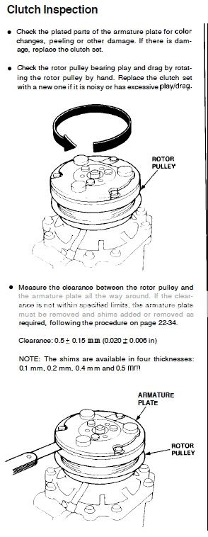
The next steps are to identify the clutch component that is at fault.
1) Measure the clutch clearance.
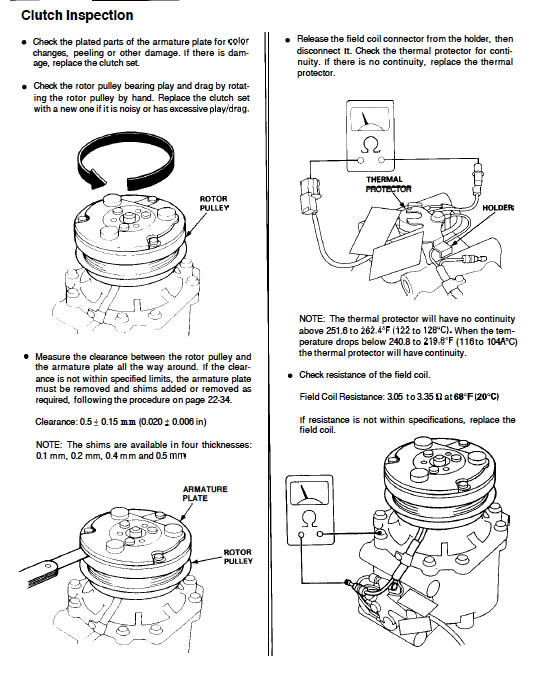
2) Measure the resistance of the coil.
3) Check the thermal protector for continuity.
Last edited by Former User; 06-09-2011 at 07:29 AM.

Trending Topics
06-09-2011, 09:52 AM
#8
06-09-2011, 07:01 PM
#9
Honda-Tech Member
Thread Starter
Yes, i hooked up my gauges last night. I dont have the exact pressures but they definitely seemed within range; both on the high side and low side. The r134a level is ok because the ac works sometimes and then sometimes it doesnt. I need to check the suggested parts tomorrow
06-14-2011, 01:10 PM
#10
Honda-Tech Member
Thread Starter
This^ finding unambiguously shows that the clutch cannot engage despite receiving voltage.
The next steps are to identify the clutch component that is at fault.
1) Measure the clutch clearance.
2) Measure the resistance of the coil.
3) Check the thermal protector for continuity.
The next steps are to identify the clutch component that is at fault.
1) Measure the clutch clearance.
2) Measure the resistance of the coil.
3) Check the thermal protector for continuity.
I know the thermal protector is good because I hooked an LED in parallel between it and the coil, and ran it inside the cabin of the car. I did this so I can see in real time without disconnecting things, if/when the compressor is getting power when the clutch doesnt kick on. It looks like when the clutch doesnt kick on, the clutch is always getting power. This seems to happen only/mostly when it is hot out. One thing I noticed last night is that the system seemed to cycle like the AC was working (it wasnt blowing any cold air) on and off. I could tell that the coil must have been using up electricity while it was cycling because (the condenser fan was already running the whole time) when the LED lit up (showing there was power to the coil) the engine sped up a little like there was more current draw on the system.
06-14-2011, 02:47 PM
#11
In that picture, do you just measure the clutch with a feeler gauge on the very outside lip between the plate and pulley? or do you stick the gauge far in between the pulley and the plate? th. ere seems to be a sort of lip inside between the plate and pulley
I know the thermal protector is good because I hooked an LED in parallel between it and the coil, and ran it inside the cabin of the car. I did this so I can see in real time without disconnecting things, if/when the compressor is getting power when the clutch doesnt kick on. It looks like when the clutch doesnt kick on, the clutch is always getting power. This seems to happen only/mostly when it is hot out. One thing I noticed last night is that the system seemed to cycle like the AC was working (it wasnt blowing any cold air) on and off. I could tell that the coil must have been using up electricity while it was cycling because (the condenser fan was already running the whole time) when the LED lit up (showing there was power to the coil) the engine sped up a little like there was more current draw on the system.
I know the thermal protector is good because I hooked an LED in parallel between it and the coil, and ran it inside the cabin of the car. I did this so I can see in real time without disconnecting things, if/when the compressor is getting power when the clutch doesnt kick on. It looks like when the clutch doesnt kick on, the clutch is always getting power. This seems to happen only/mostly when it is hot out. One thing I noticed last night is that the system seemed to cycle like the AC was working (it wasnt blowing any cold air) on and off. I could tell that the coil must have been using up electricity while it was cycling because (the condenser fan was already running the whole time) when the LED lit up (showing there was power to the coil) the engine sped up a little like there was more current draw on the system.
The ECU causes the idle speed to increase when the A/C button is pressed even if the compressor clutch fails to engage.
Did you measure the resistance of the coil?
06-23-2011, 04:36 PM
#12
Honda-Tech Member
Thread Starter
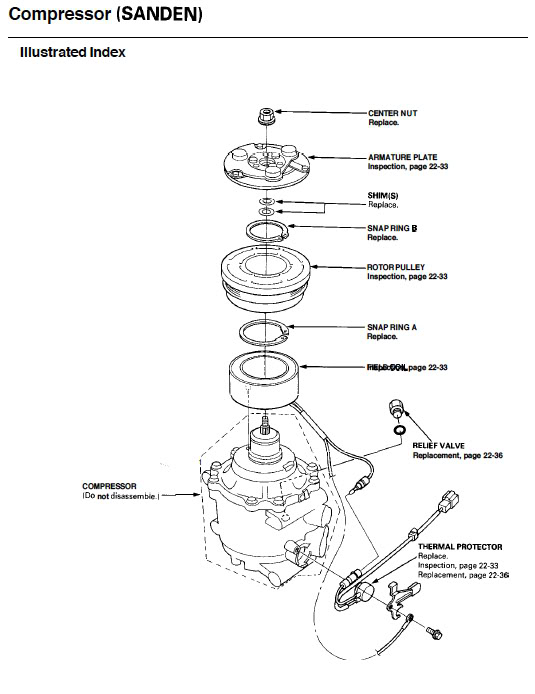
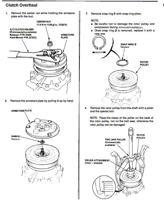
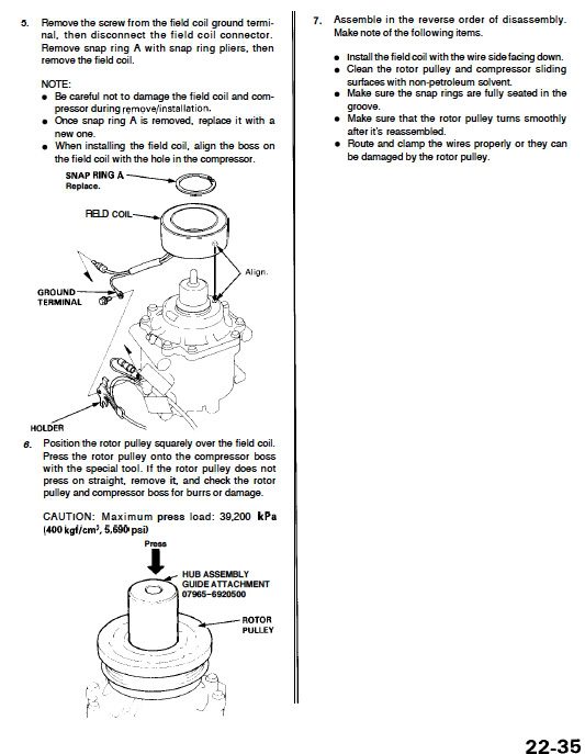
It looks like it is the air gap that is the problem. When the compressor doesnt turn on and i tap the plate, the AC engages. Do I just pull off the plate? or do i have to pull the whole pulley off as well? And do I have to pull the compressor off of the system to do this or can it be done while bolted to the car?
06-23-2011, 05:10 PM
#13
Buy an OEM clutch set and install it. For example, check the Majestic Honda site.
The clutch can be removed and installed without disconnecting the A/C lines. Remove the compressor bolts and suspend the compressor from a rope. This should create the needed space to do the work.
The clutch can be removed and installed without disconnecting the A/C lines. Remove the compressor bolts and suspend the compressor from a rope. This should create the needed space to do the work.

Thread
Thread Starter
Forum
Replies
Last Post
akb427
Honda Civic (2001 - 2005)
2
06-28-2013 08:51 AM
mikekh10a
Honda Civic / Del Sol (1992 - 2000)
12
06-14-2012 12:17 PM
JesseCRX
Honda CRX / EF Civic (1988 - 1991)
23
08-11-2008 04:40 PM