
Fog light brake ducts and cooling theories
 03-20-2012, 09:48 PM
#76
Honda-Tech Member
Thread Starter
I have seen those HPD kits. Good stuff indeed, and works of art in themselves! They will work with their respective cars just great and I can't knock that, though I would like to see a setup like that with a DA,DC2 or EG EK EF civic which were the models I had in mind. I still don't think that is possible in the complexity or 3" size. I also think most on here are DIY garage guys who won't spend 350$+ on a fancy ducting system. I can make something like that, but I think a cheap little spindle duct and some flex hose is more in the budget of HPDE'ers and weekend warriors.
Thanks for the contributions and I see how the ducting should be scientifically, and physically how it will fit in to a certain package. Now I have some new ideas and might try a few things with 2" that will fit in the desired areas, satisfy the smooth tube with minimal bend suggestions and still not rub the pulley or the wheels while turning.
Thanks for the contributions and I see how the ducting should be scientifically, and physically how it will fit in to a certain package. Now I have some new ideas and might try a few things with 2" that will fit in the desired areas, satisfy the smooth tube with minimal bend suggestions and still not rub the pulley or the wheels while turning.
Last edited by JW racing; 03-21-2012 at 06:58 AM.
 03-21-2012, 07:07 AM
#77
Honda-Tech Member
Join Date: Apr 2009
Location: Fontana Ca.
Posts: 480
Likes: 0
Received 0 Likes
on
0 Posts
Those pieces look really nice but there is a fundamental problem with that, I can probably recreate them , Justin can do it too for his car and I'm sure some of the other guys can, but you want to sell to the general public not race teams.
We know a race team with decent budget can knock out some awesome stuff , with some time I can build me some stuff out of carbon if I want to.
By the way they still use hose so for us mere mortals what is just another 1/2 a foot of hose.
Sometimes a little of common sense goes a longer way than an equation. That they don't teach it in school.
03-21-2012, 08:59 PM
#78
Honda-Tech Member
Those pieces look really nice but there is a fundamental problem with that, I can probably recreate them , Justin can do it too for his car and I'm sure some of the other guys can, but you want to sell to the general public not race teams.
We know a race team with decent budget can knock out some awesome stuff , with some time I can build me some stuff out of carbon if I want to.
By the way they still use hose so for us mere mortals what is just another 1/2 a foot of hose.
Sometimes a little of common sense goes a longer way than an equation. That they don't teach it in school.
We know a race team with decent budget can knock out some awesome stuff , with some time I can build me some stuff out of carbon if I want to.
By the way they still use hose so for us mere mortals what is just another 1/2 a foot of hose.
Sometimes a little of common sense goes a longer way than an equation. That they don't teach it in school.
03-21-2012, 09:25 PM
#79
Honda-Tech Member
Maybe my paper towel tube vs straw test lied? On a true race car that is not a production vehicle this may be right, but as mentioned one would need blowers to supply the proper cfm because the speed of the air will slow down by the time it reaches the rotor with such large volume. More cfm yes, but with much less velocity unless a blower is utilized. Velocity was mentioned in that post about tube size.
I also wonder how people here can fit 3 and 4" hose under the frame rail without hitting the crank pulley or the tires eating the hose while turning in the paddock. I speak from experience not some calculations. 95% of the people on here would only be able to fit 2" hose and maybe 2.5 will fit in some instances, 3" will not fit without serious rubbing and 4 is a fallacy.
I also wonder how people here can fit 3 and 4" hose under the frame rail without hitting the crank pulley or the tires eating the hose while turning in the paddock. I speak from experience not some calculations. 95% of the people on here would only be able to fit 2" hose and maybe 2.5 will fit in some instances, 3" will not fit without serious rubbing and 4 is a fallacy.
To minimize heat transfer into the calipers, use titanium or stainless pistons or backing plates that sit behind the brake pads. If I was making brake pads, I would use titanium backing plates in the pad itself or maybe a stainless piece since each of these materials has a significantly lower conductivity than simple steel that is typically used. Also, ceramics could be used if done properly. This way, much heat is conducted into the brake fluid due to the lower conductivity of the pistons and/or backing plates.
Because this entire system design requires some fluid dynamics (air is a fluid) knowledge and an understanding of how air moves through ducts and inlet conditions, simply stating that common sense can somehow be used instead of understanding what is happening in terms of the physics involved is incorrect. Sure, you might through trial and error come up with a solution that works okay, but you'll almost certainly be creating a duct system that generates more drag than it should and the flow rate through the ducting won't be even close to optimum.
03-22-2012, 08:05 AM
#80
Honda-Tech Member
Thread Starter
Remember how this whole system works. You have high pressure at the inlet and lower pressure thanks to the guide vanes in the rotor. In between you have the inlet condition where it is imperative that you turn the air into the tubing properly to make sure you don't have flow separation at the inlet. If you do have flow separation, the flow rate through the ducting will be reduced roughly in proportion to how bad the inlet was designed..
So on the other hand as far as the inlet itself, something like the EG fog light duct will be ok with its smooth naca inlet design, but for someone just sticking a tube end in the grille or fog light area hoping to capture enough air to feed the rotor will not be doing much as the inlet is not complete.
So would the average person be able to use a coned velocity stack of sorts or must it be a funneled naca type duct? I assume a funnel would be much better.
Is it the same for the flex hose to the metal spindle duct itself, if there is a step or rough transition from hose to the spindle you will create a disturbance there as well? Now if I made that tube section on the box I have much longer and incorporate a gentle curve, to make for less overall flex hose would that help? I think it would by your guys' suggestions, also the fiberglass inlet itself to have a much longer exit section. I can eliminate about 1.5 ft+ of flex hose if I extend those two sections dramatically, which wouldn't be a problem at all for me to do.
Last edited by JW racing; 03-22-2012 at 08:28 AM.
03-22-2012, 08:59 AM
#81
Honda-Tech Member
iTrader: (1)
Join Date: Nov 2007
Location: progress starts now.
Posts: 1,518
Likes: 0
Received 6 Likes
on
5 Posts
Aside From the hose, Doesnt any form of ducting begin lose its efficiency once you reach a certain speed? The frontal force is more than the ducting can flow and the air begins to pass right over?
It wouldn't be to good on the EG bumper, But i've made a few velocity stacks and think that this one might be good for certian models. It's basically a trimmed down copy of the velocity stack that came in the Mugen EK air boxes. 4.5 inch O.D and uses 3" outlet. maybe something like this flush mounted in the bumper would flow better?
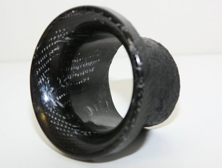
It wouldn't be to good on the EG bumper, But i've made a few velocity stacks and think that this one might be good for certian models. It's basically a trimmed down copy of the velocity stack that came in the Mugen EK air boxes. 4.5 inch O.D and uses 3" outlet. maybe something like this flush mounted in the bumper would flow better?
03-22-2012, 09:34 AM
#82
Honda-Tech Member
Understood, good point to add to the thread. You are speaking of the transition from the inlet duct to the flex hose correct? If it is not optimal or smooth the air will break away from the surface creating turbulence and disturbance in flow. I see.
So on the other hand as far as the inlet itself, something like the EG fog light duct will be ok with its smooth naca inlet design, but for someone just sticking a tube end in the grille or fog light area hoping to capture enough air to feed the rotor will not be doing much as the inlet is not complete.
So would the average person be able to use a coned velocity stack of sorts or must it be a funneled naca type duct? I assume a funnel would be much better.
Is it the same for the flex hose to the metal spindle duct itself, if there is a step or rough transition from hose to the spindle you will create a disturbance there as well? Now if I made that tube section on the box I have much longer and incorporate a gentle curve, to make for less overall flex hose would that help? I think it would by your guys' suggestions, also the fiberglass inlet itself to have a much longer exit section. I can eliminate about 1.5 ft+ of flex hose if I extend those two sections dramatically, which wouldn't be a problem at all for me to do.
Anyone familar with old Chevy V8 heads knows that the short side radius inside the intake ports was too sharp for proper airflow into the combustion chamber. As a result, at higher RPM's the flow would separate off of this port floor and hurt horsepower. A proper porting job could result in a horsepower increase of over 10% over a wide range of RPM's just by increasing this radius to the point where flow separation was either eliminated or substantially reduced. This same concept applies to the floor of the ducting inlet for brake cooling. The net effect of a good design over a poor one is that you could get more flow from a 2" duct system than a poorly designed 3" system.
Just sticking a tube, even with a bellmouth, out of the front of the car will result in some flow to the rotor due in part to the low pressure outlet thanks to the spinning rotor vanes and in part due to the fact that some air is traveling at some angle relative to the tube opening. But this isn't very effecient or effective. A proper design would look much more like a NACA duct, but with a radiused floor so that the air is turned about 90 degrees before you begin running the flexible aeroduct tubing.
An enterprising person could find a workable design by fabricating an aluminum piece whereby modeling clay is used to find the shape the best works. You could use a turbine flow meter, a manometer, ect. and you can see how the flow changes in real time between various design iterations at a given speed.
03-22-2012, 10:25 AM
#83
Honda-Tech Member
Thread Starter
Thanks John,
The wheels in my mind are turning and I am going to apply a few things you and Rene mentioned. Reduce some flex tubing length, extend the solid smooth tubing areas, make some smoother radius turns in a few areas.
What I would like to do is extend the exit portion of the entry duct about a foot so there is less hose and a longer smoother entry of air flow. I will extend the tube section of the spindle side as well to get the same results.
The main problem I face is the space on the frame rail, the wheel rubs, and the crank pulley and tranny limit the space under the frame rail. Is it possible to run an oval or rectangle section of pipe to clear the wheels and crank pulley without hurting the flow too much?
Last edited by JW racing; 03-22-2012 at 10:52 AM.
03-22-2012, 11:40 AM
#84
Honda-Tech Member
Going under the trans/motor and attaching the hose to the splitter is the straightest and safest route.
03-24-2012, 08:55 AM
#85
Honda-Tech Member
Thanks John,
The wheels in my mind are turning and I am going to apply a few things you and Rene mentioned. Reduce some flex tubing length, extend the solid smooth tubing areas, make some smoother radius turns in a few areas.
What I would like to do is extend the exit portion of the entry duct about a foot so there is less hose and a longer smoother entry of air flow. I will extend the tube section of the spindle side as well to get the same results.
The main problem I face is the space on the frame rail, the wheel rubs, and the crank pulley and tranny limit the space under the frame rail. Is it possible to run an oval or rectangle section of pipe to clear the wheels and crank pulley without hurting the flow too much?
The wheels in my mind are turning and I am going to apply a few things you and Rene mentioned. Reduce some flex tubing length, extend the solid smooth tubing areas, make some smoother radius turns in a few areas.
What I would like to do is extend the exit portion of the entry duct about a foot so there is less hose and a longer smoother entry of air flow. I will extend the tube section of the spindle side as well to get the same results.
The main problem I face is the space on the frame rail, the wheel rubs, and the crank pulley and tranny limit the space under the frame rail. Is it possible to run an oval or rectangle section of pipe to clear the wheels and crank pulley without hurting the flow too much?
For example, for your ducting design, by making sure you have an effective rotor shield with the duct outlet designed for proper flow, you will have created a good low pressure source that might allow a smaller diameter aeroduct tubing. This is because when the flow in a system is driven by a larger pressure gradient (i.e. difference between the inlet and outlet pressures) you will almost invariably get a larger air flow rate through the system which would allow you to more favorably package your design in a smaller space. Of course, it will depend on what the requirements of the given brake system's cooling requirements. In addition to just the ducting system, sometimes you may find a rotor of the same size but with a different internal vane design will actually decease the pressure at the duct outlet (rotor side) and improve performance even more. Once again, this brake cooling duct system involve many facets to the design that isn't as simple as just what the inlet design looks like, or what size aeroduct tubing is used.
 03-28-2012, 03:13 AM
#88
Honda-Tech Member
moar pics. Don't be stingy with your setups! 
Pics of how you get it all attached at the spindle/caliper/disc end of things would be HOT (pun intended).
Pics of how you get it all attached at the spindle/caliper/disc end of things would be HOT (pun intended).
03-28-2012, 07:39 AM
#89
Honda-Tech Member
Thread Starter
Do you have oem calipers or wilwoods or ? Oem I can share. Though Mounting the spindle duct to the wilwoods is a trick that took me a while and I rather keep that to myself and people who buy the kits. It's easy for someone to copy what I did after a post here and I don't want that. There is a picture of a mounted wilwood box on my facebook page though.
03-28-2012, 11:07 AM
#90
04-06-2012, 07:51 AM
#91
Honda-Tech Member
Thread Starter
Quite a few spindle ducts moving out, anyone want some of this batch before they are gone? #weldingmore
I have found on the DX upright there needs to be some trimming for the brake line and the Axle. I think user Known will post this up soon to help us out.
I have found on the DX upright there needs to be some trimming for the brake line and the Axle. I think user Known will post this up soon to help us out.
04-07-2012, 08:23 PM
#92
Honda-Tech Member
Join Date: Nov 2001
Location: USA
Posts: 3,788
Likes: 0
Received 0 Likes
on
0 Posts
I'm redoing my ducting and I bought a 4" to 2.5" reducer that used for dryers. What's nice is I can put the bumper on with the hoses sticking through, attached them to the reducers then zip tie the reduces into the bumper. Easy on, easy off.
I got the duct to point at the center of everything and even when the wheel is at full lock it doesn't affect the hose.
Is it perfect? No.. but it's better then it was before and I'm really looking forward to doing some damn racing this year! I HATE the off season!


And no, I will not resize my pictures
I got the duct to point at the center of everything and even when the wheel is at full lock it doesn't affect the hose.
Is it perfect? No.. but it's better then it was before and I'm really looking forward to doing some damn racing this year! I HATE the off season!
And no, I will not resize my pictures
04-15-2012, 11:54 PM
#93
Honda-Tech Member
Anybody remember these units here?
http://www.ipgparts.net/blog/general...r-ita-integra/

They sure look the part and I guess apart from the substantial length of corrugated tubes, they ought to work quite well with a bit of massaging.
Also something similar I recall seeing many many years ago from the guys at SandMRacing.
http://web.archive.org/web/200602190...tventside2.jpg
http://web.archive.org/web/200602190...ctswelded1.jpg
http://www.ipgparts.net/blog/general...r-ita-integra/
They sure look the part and I guess apart from the substantial length of corrugated tubes, they ought to work quite well with a bit of massaging.
Also something similar I recall seeing many many years ago from the guys at SandMRacing.
http://web.archive.org/web/200602190...tventside2.jpg
http://web.archive.org/web/200602190...ctswelded1.jpg
04-16-2012, 07:06 AM
#94
Honda-Tech Member
Thread Starter
I remember those IPG units. Not bad but a bit bulky for the spindle imo. The bumper inlets are mediocre at best.
05-14-2012, 10:25 AM
#98
Honda-Tech Member
Join Date: Feb 2011
Posts: 876
Likes: 0
Received 0 Likes
on
0 Posts

 05-14-2012, 10:50 AM
#99
Honda-Tech Member
Join Date: Nov 2001
Location: USA
Posts: 3,788
Likes: 0
Received 0 Likes
on
0 Posts
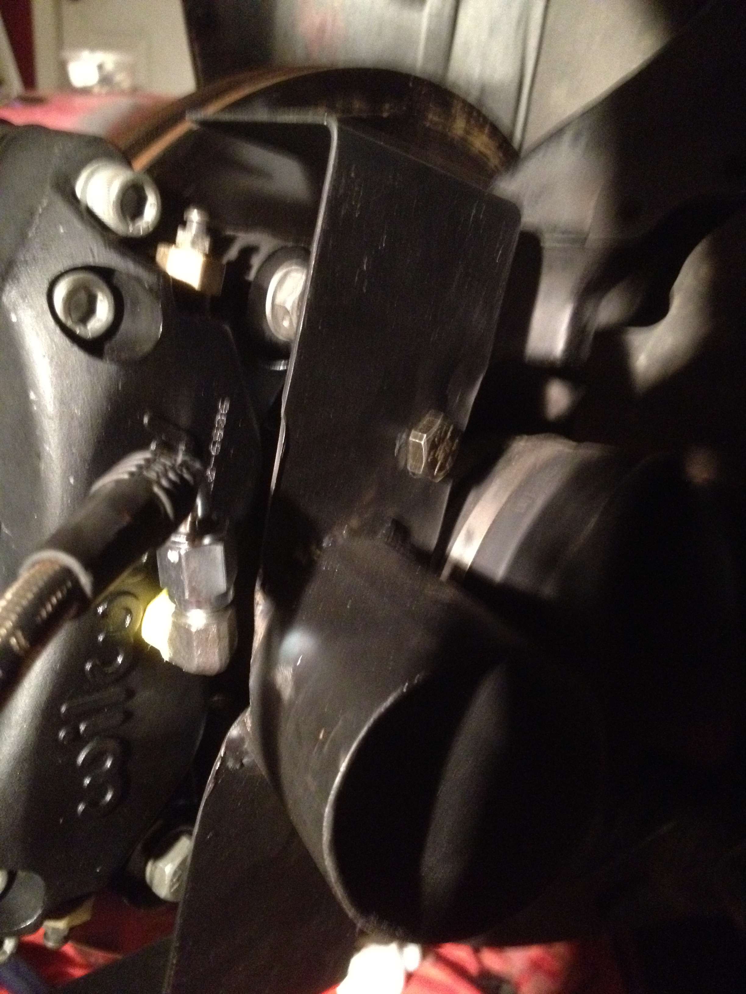
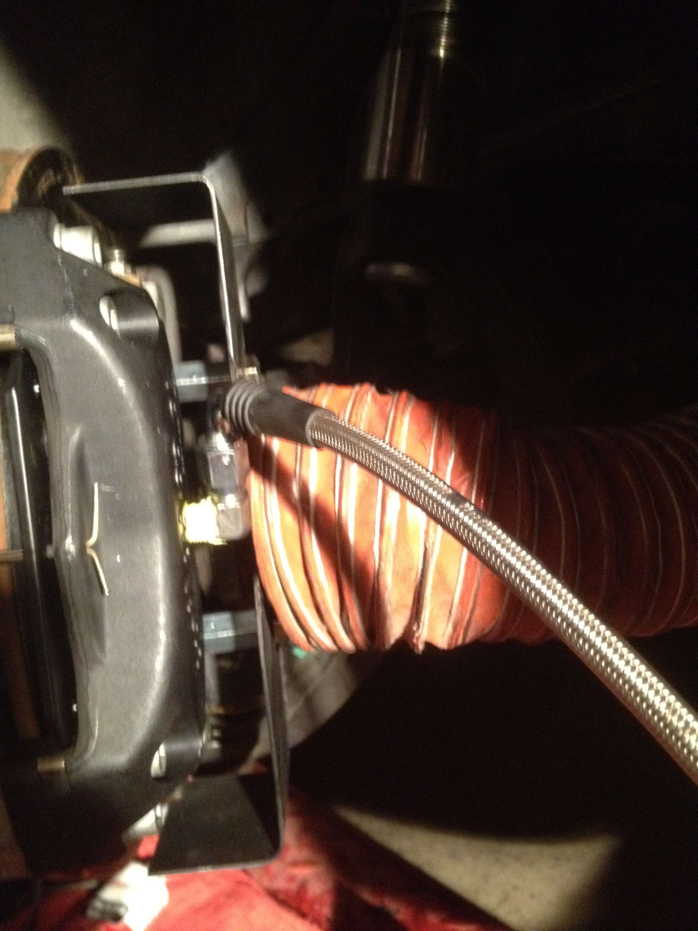
I tried other routes but found that it got crushed during steering movement.
Some pics for reference.

 05-14-2012, 04:35 PM
#100
Honda-Tech Member
iTrader: (1)
Join Date: Jan 2003
Location: orlando, fl, us
Posts: 1,984
Likes: 0
Received 0 Likes
on
0 Posts
JW box ducting..... going to have to modify them for my downgrade to dx calipers again to run with the slow guys. I was very happy with this setup, ducting is hard to route without big turns but it worked. I havent gotten to making fixed aluminum or ss tubes to eliminate hose yet.
Crappy photos
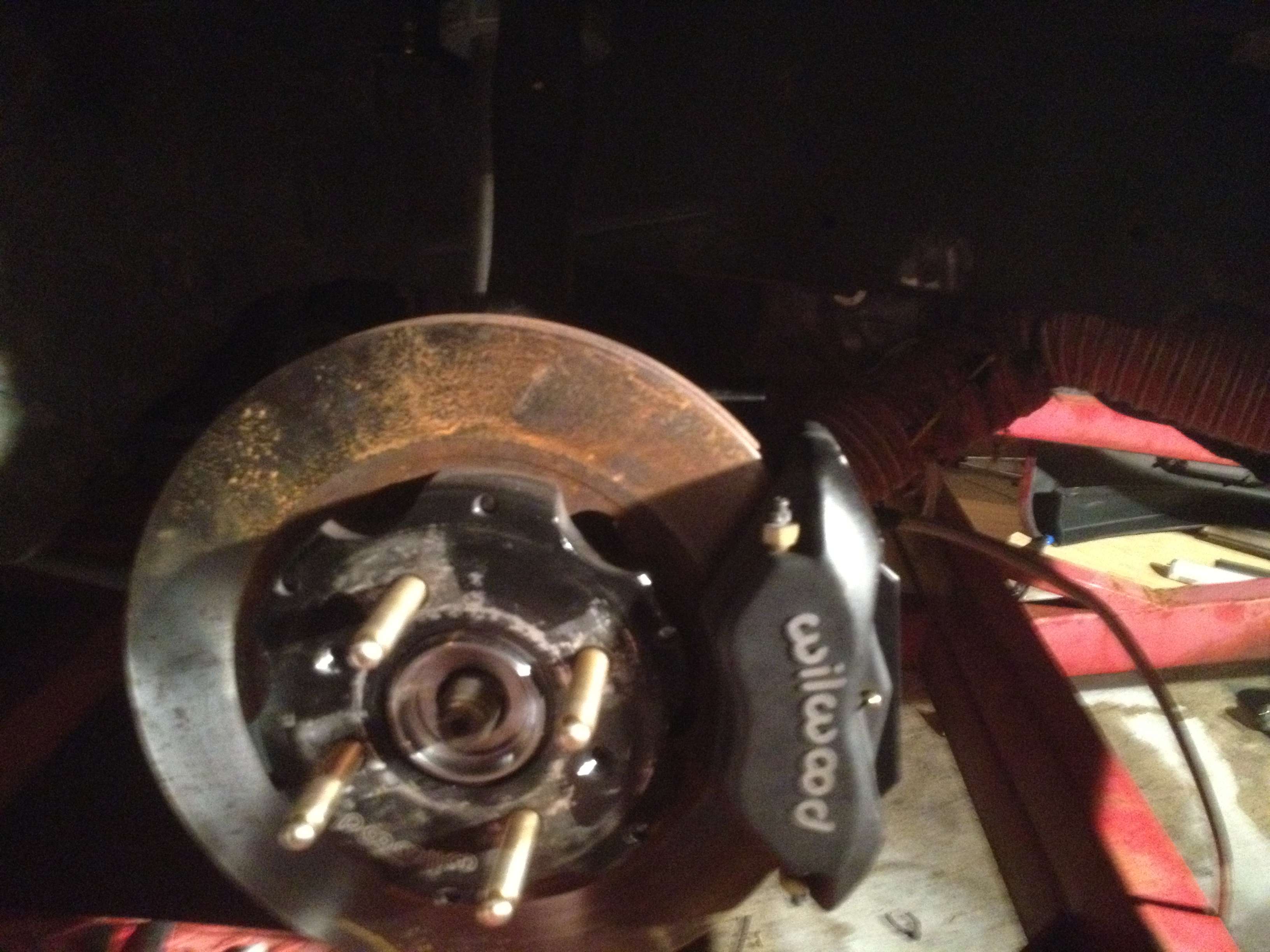
Crappy photos