
DIY Bilstein revalve project, part 2
 11-24-2008, 05:04 AM
#1
Honda-Tech Member
Thread Starter
OK, I got some Bilstein Sport front shocks, mainly for the OEM fitment appeal. I'm kind of tired of ghetto rigging up adapters. There are some other Bilstein revalve guide out on the interweb, but I thought I might post some hints anyway.
First up is to vent the shock. Start by drilling a small pilot hole to let the gas out. PSSSSSSSSSSHHHHHH!
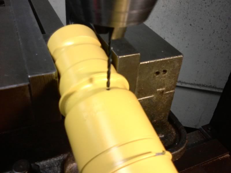
Next drill a bigger hole and tap it with NPT taper 1/8-27. (That's the schrader size from Bilstein). In my case, I drilled at an angle to try to get the valve as low on the body as possible, but it isn't necessary. You definitely want to do this on a mill, or have a machinist do it for you since it's easy to have the drill wander and ovalize the hole. After the pilor hole, I drilled with an end mill since it can cut straight down and sideways and doesn't deflect sideways. Then machine tap.
Now it turns out that the wall thickness of the tube is only 2mm, which means you can get about 2 threads in. Is that enough? I dunno, but the pressure on a hole of this size is only about 10 lbs or so. Don't feel bad if you mess this up, coz you can also do what Dennis Grant did and weld it in.
Warning: The inside of your shock is now filled with metal shards. Do not do anything that might move the piston. Go wash this out with soap and water.
Now shake your shock around. Hear that slooshing sound? That's the sound of Bilstein packing plenty of air into the oil side of the piston. Nice job.
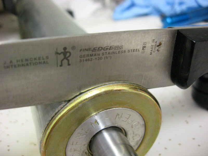
Fortunately, these OEM shocks DO have a dust seal on top. Carefully hammer in a knife all around the edge and gently pry it out. I know this isn't the same shock, but whatever. You won't see me using my Wusthof for this task!
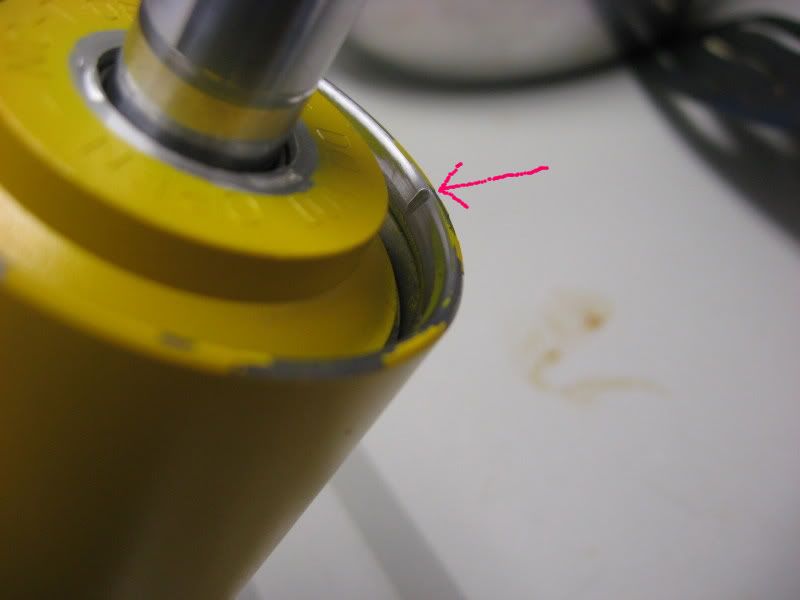
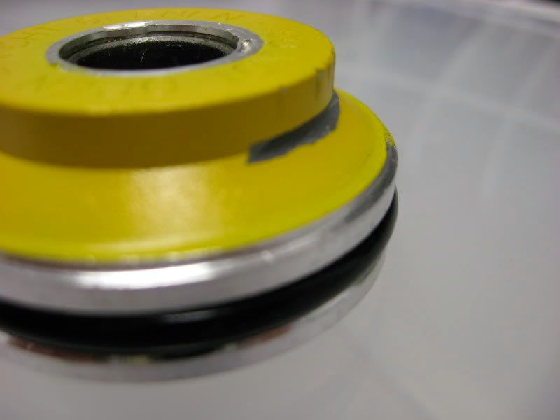
Hey, this top cap looks familiar. Yay for commodity parts. Now go file that little bleed groove.
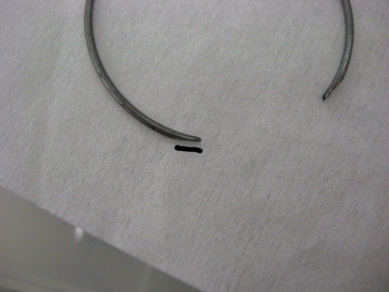
Press the top cap down a little bit, and take off the circlip.
Take this opportunity to file down the outer edge of the circlip to make it easier to pry out in the future. Otherwise, I guarantee you will end up hating life.
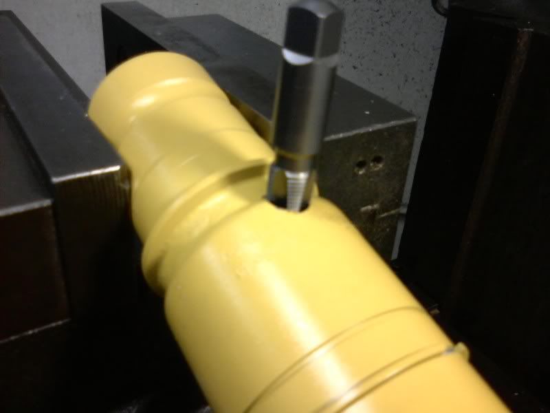
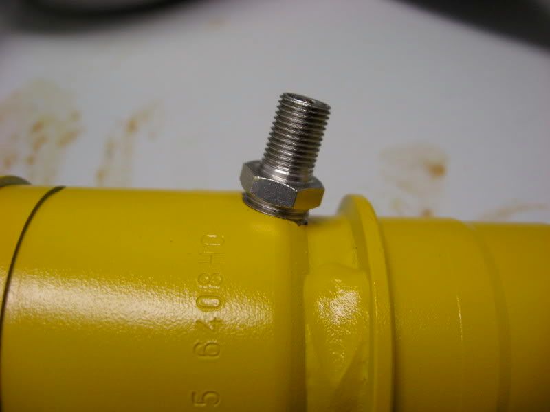
Temporarily thread the schraeder valve into the hole you tapped, using grease or some other thread sealant to prevent leaks. This is only temporary, as you will be taking the schraeder out again.
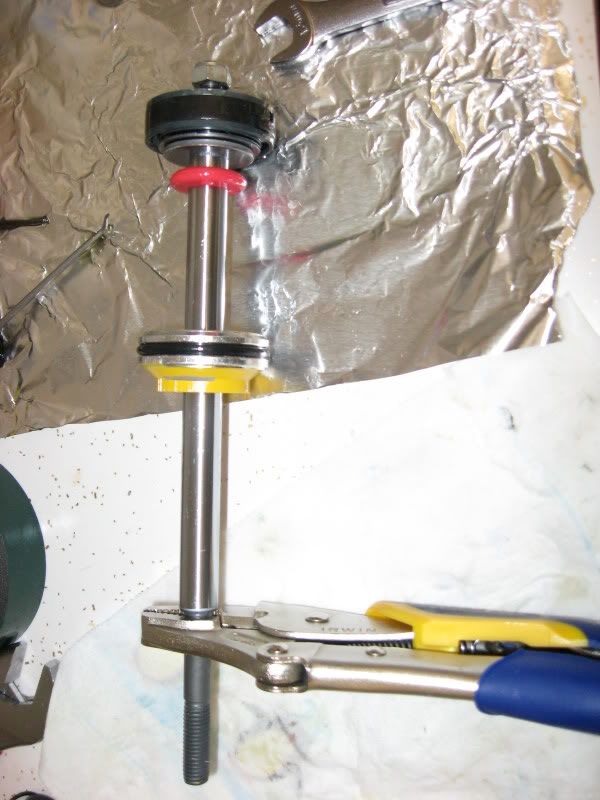
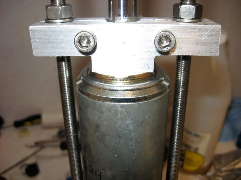
Carefully pressureize out the top cap, making sure to use that top seal pressing down tool so at not to send the cap flying. Also get ready to catch the oil that will come out.
Once you have the top cap off, put it to the bandsaw to cut two notches in for future prying out.
Carefully pressurize out the dividing piston and wash out any remaining bits of metal inside the shock.
Now get ready to put the schrader in for good. I used thread sealant, but it turns out that they typically DON'T dry when exposed to air. I gooped some extra around the edges, waited a day, wiped off the excess, then went over it again with epoxy. Hope it holds...
The piston is likely held onto the shaft via a nut that has been "staked", i.e. they purposely jacked up the threads on the nut so as not the have it come off. Good luck getting that nut off. I used a very tightly clamped vice grip on the upper part of the piston shaft, which doesn't pass by any seals. Maybe there is another good way to clamp down on the piston shaft, I dunno. Be careful not to bend anything out at this point. If you ever get the nut loosened, don't take it straight off, but rather massage it back and forth a few times to help reshape the threads. Most likely, that won't help much, and you should get a M8x1 die to clean up the threads. You can also use a file to take off the burr at the last thread.
Since I don't have attachments for this particular shock on my dyno, I just put this piston into my other Bilstein shock body. Yay for commodity parts again.
Here's a dyno plot for the Bilstein sport shock that is for the front of Civic EK, compared to a Koni yellow shock I pulled off my car, adjusted for the 425# springs.
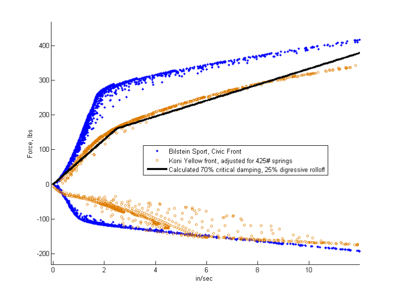
In red/black I plotted a curve for the idealized damping curve if you want to go by that 65-70% critical damping rule. Holy crap, that Bilstein comes way overdamped. "Bilsteins ride a bit harsh" probably turns out to be true. Also note that the low speed rebound an compression damping is the same. Even though this shock has the new COB / RBT piston with the check valve, they aren't using it. No idea why. No, actually I DO have an ida why. It's because their older style piston didn't have this feature, so they were forced to valve it like this. And then they were too lazy to re-shim for the new type of piston.
Anyway, put your new shims on the shock, making sure to use the check valve that this new piston type allows. Be sure to keep the area lint free, as even a little bit getting caught between the shims will mess up your dyno plots. I used aluminum foil and low lint wipes in the working area.
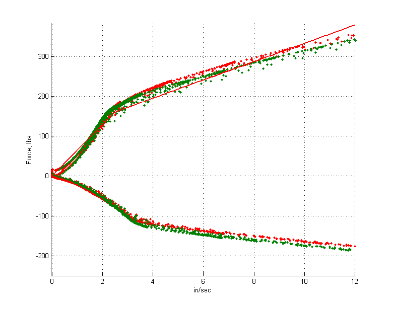
See, I have asymmetric low speed rebound and compression damping now!
Put everything back together, making sure to set the dividing piston at the right height, and that it won't hit the schraeder valve. In my case, I think I had about 1/2" -3/4" clearance before the piston would hit either the shaft piston at full compression or the schraeder. You can also check the progressiveness of the air space at this time by partially pumping up the shock, then pushing the shaft all the way down. In my case, I had a pressure increase of about 55%.
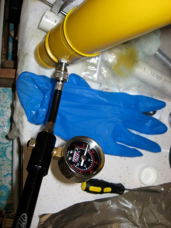
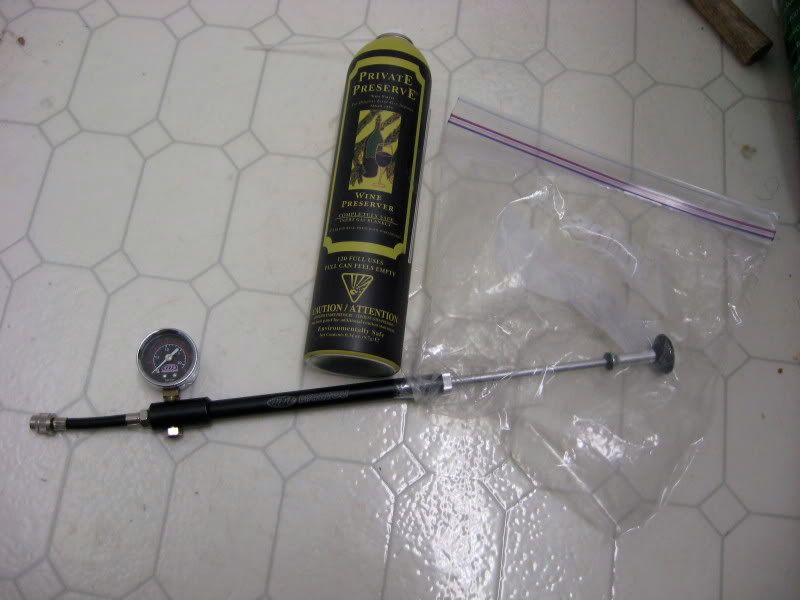
Advanced nitrogen filling tool:
Use your spiffy top hat pressing down tool to press the top cap and wiper seal back on.
Ol Dun!
First up is to vent the shock. Start by drilling a small pilot hole to let the gas out. PSSSSSSSSSSHHHHHH!
Next drill a bigger hole and tap it with NPT taper 1/8-27. (That's the schrader size from Bilstein). In my case, I drilled at an angle to try to get the valve as low on the body as possible, but it isn't necessary. You definitely want to do this on a mill, or have a machinist do it for you since it's easy to have the drill wander and ovalize the hole. After the pilor hole, I drilled with an end mill since it can cut straight down and sideways and doesn't deflect sideways. Then machine tap.
Now it turns out that the wall thickness of the tube is only 2mm, which means you can get about 2 threads in. Is that enough? I dunno, but the pressure on a hole of this size is only about 10 lbs or so. Don't feel bad if you mess this up, coz you can also do what Dennis Grant did and weld it in.
Warning: The inside of your shock is now filled with metal shards. Do not do anything that might move the piston. Go wash this out with soap and water.
Now shake your shock around. Hear that slooshing sound? That's the sound of Bilstein packing plenty of air into the oil side of the piston. Nice job.
Fortunately, these OEM shocks DO have a dust seal on top. Carefully hammer in a knife all around the edge and gently pry it out. I know this isn't the same shock, but whatever. You won't see me using my Wusthof for this task!
Hey, this top cap looks familiar. Yay for commodity parts. Now go file that little bleed groove.
Press the top cap down a little bit, and take off the circlip.
Take this opportunity to file down the outer edge of the circlip to make it easier to pry out in the future. Otherwise, I guarantee you will end up hating life.
Temporarily thread the schraeder valve into the hole you tapped, using grease or some other thread sealant to prevent leaks. This is only temporary, as you will be taking the schraeder out again.
Carefully pressureize out the top cap, making sure to use that top seal pressing down tool so at not to send the cap flying. Also get ready to catch the oil that will come out.
Once you have the top cap off, put it to the bandsaw to cut two notches in for future prying out.
Carefully pressurize out the dividing piston and wash out any remaining bits of metal inside the shock.
Now get ready to put the schrader in for good. I used thread sealant, but it turns out that they typically DON'T dry when exposed to air. I gooped some extra around the edges, waited a day, wiped off the excess, then went over it again with epoxy. Hope it holds...
The piston is likely held onto the shaft via a nut that has been "staked", i.e. they purposely jacked up the threads on the nut so as not the have it come off. Good luck getting that nut off. I used a very tightly clamped vice grip on the upper part of the piston shaft, which doesn't pass by any seals. Maybe there is another good way to clamp down on the piston shaft, I dunno. Be careful not to bend anything out at this point. If you ever get the nut loosened, don't take it straight off, but rather massage it back and forth a few times to help reshape the threads. Most likely, that won't help much, and you should get a M8x1 die to clean up the threads. You can also use a file to take off the burr at the last thread.
Since I don't have attachments for this particular shock on my dyno, I just put this piston into my other Bilstein shock body. Yay for commodity parts again.
Here's a dyno plot for the Bilstein sport shock that is for the front of Civic EK, compared to a Koni yellow shock I pulled off my car, adjusted for the 425# springs.
In red/black I plotted a curve for the idealized damping curve if you want to go by that 65-70% critical damping rule. Holy crap, that Bilstein comes way overdamped. "Bilsteins ride a bit harsh" probably turns out to be true. Also note that the low speed rebound an compression damping is the same. Even though this shock has the new COB / RBT piston with the check valve, they aren't using it. No idea why. No, actually I DO have an ida why. It's because their older style piston didn't have this feature, so they were forced to valve it like this. And then they were too lazy to re-shim for the new type of piston.
Anyway, put your new shims on the shock, making sure to use the check valve that this new piston type allows. Be sure to keep the area lint free, as even a little bit getting caught between the shims will mess up your dyno plots. I used aluminum foil and low lint wipes in the working area.
See, I have asymmetric low speed rebound and compression damping now!
Put everything back together, making sure to set the dividing piston at the right height, and that it won't hit the schraeder valve. In my case, I think I had about 1/2" -3/4" clearance before the piston would hit either the shaft piston at full compression or the schraeder. You can also check the progressiveness of the air space at this time by partially pumping up the shock, then pushing the shaft all the way down. In my case, I had a pressure increase of about 55%.
Advanced nitrogen filling tool:
Use your spiffy top hat pressing down tool to press the top cap and wiper seal back on.
Ol Dun!
Last edited by beanbag; 11-24-2008 at 09:01 PM. Reason: Added more pics
 08-19-2009, 05:31 AM
#4

Join Date: Aug 2009
Posts: 8
Likes: 0
Received 0 Likes
on
0 Posts
Bringing this thread back from the dead. Great work. Does anybody know offhand the formula for figuring out the %critically damped for a given spring rate / shock piston velocity.
Cory
Cory
08-19-2009, 09:46 AM
#5
Honda-Tech Member
You also need to compute the equivalent spring rate of the suspension spring and the equivalent damping coefficient.
After determining the equivalent mass, damping coefficient and spring rate, then you need to look at the solution to the free vibration with viscous damping (dashpot) differential equation.
Critical Damping Constant = C = 2*square-root(equivalent spring rate X equivalent mass)
Thus, for a 70% critically damped suspension, you need to make the low-speed equivalent damping coefficient Ceq = .7*C and then by using the suspension's motion ratio, determine what the damping coefficient you need and use the damper dyno to fine tune the low speed control.
The answer to your last question, is that you compute the critical damping coeffiecient for a range of shock velocities and not just a singe velocity. This of course, assumes that the damper's dashpot damping coefficient is linear in the range of velocities in question.
08-19-2009, 10:49 AM
#6
Join Date: Aug 2009
Posts: 8
Likes: 0
Received 0 Likes
on
0 Posts
Thanks.
This is just what I was looking for. I've been told that the equivalent mass can be estimated by using the full weight of everything on the outboard end of the suspension arms (wheel/tire, hub, brake, caliper, etc.) and 50% of the suspension arms springs and shocks. This seems to ignore the mass and spring rate of the anti-sway bars. Does this sound like a reasonable way to do it? It would seem more accurate if you figured in the mass of the end-links and the arms of the anti-sway bar (multiplied by the % distance of the suspension arm length that they attach to). The effective rate for the bar is,I think, usually ignored, and shouldn't have any effect on the mass anyway. Is the damping force that you use to find the equivalent damping force just measured on a shock dyno? Or, do you need shock velocity measurements from on course? Or is it based entirely on the natural frequency of the system as computed in the equation for the free vibration with viscous damping? Thanks again for helping out, I'm a real noob when it comes to suspension so please forgive me for any stupid questions.
Cory
08-19-2009, 12:01 PM
#7
Honda-Tech Member
Thanks.
This is just what I was looking for. I've been told that the equivalent mass can be estimated by using the full weight of everything on the outboard end of the suspension arms (wheel/tire, hub, brake, caliper, etc.) and 50% of the suspension arms springs and shocks. This seems to ignore the mass and spring rate of the anti-sway bars. Does this sound like a reasonable way to do it?
Cory
It would seem more accurate if you figured in the mass of the end-links and the arms of the anti-sway bar (multiplied by the % distance of the suspension arm length that they attach to). The effective rate for the bar is,I think, usually ignored, and shouldn't have any effect on the mass anyway.
Cory
Cory
Most people just use the two wheel analysis for determining the suspension's natural frequency. In the two wheel analysis, each wheel on the axle is assumed to encounter the same road disturbance and thus the ARB spring rate does not influence the analysis but the mass of the endlinks and the bar itself would affect the natural frenquency only by a small and often negligible amount. Thus, the wheel is assumed to be isolated (and thus no effect due to ARB coupling) when the calculations are made.
In practice, each wheel on an axle does not hit the same disturbance in straight line driving and of course, the situation in cornering is highly dependent of the action of the ARB. In the actual scenario, the ARB adds an additional equivalent spring rate (one-wheel bump), equivalent mass, and an addtional equivalent damping coefficient. Of course, because the ARB acts upon the suspension on the opposite side through an effective spring rate in series that includes the ARB rate and the suspension's spring rate, the additional equivalent masses, sping rate, and damping coefficient is somewhat smaller than for the corner of the car under review. In addition, the ARB might even introduce some Coulomb damping if the bars support bushings are really tight (like my ST bar before I modified it).
As you can see, by adding the ARB in the analysis complicates the computation substantially.
Is the damping force that you use to find the equivalent damping force just measured on a shock dyno? Or, do you need shock velocity measurements from on course? Or is it based entirely on the natural frequency of the system as computed in the equation for the free vibration with viscous damping? Thanks again for helping out, I'm a real noob when it comes to suspension so please forgive me for any stupid questions.
Cory
Cory
Trending Topics
08-19-2009, 08:59 PM
#8
Honda-Tech Member
Thread Starter
RRobb,
Judicious use of the >>, <<, and ~ symbols will allow you to bypass all of that analysis for most applications. For example, the hub/wheel is connected to the ground with a tire spring rate that is >> than the effective wheel rate, which means that you no longer have to care about the mass of all your individual suspension components and their real or virtual or imaginary or supposed or purported pivot points. The critical damping value is ~ that of the corner sprung weight plus motion ratio effects.
Secondly, the above analysis calculates unsprung suspension frequencies/damping, which are typically not as relevant as the sprung values. When people talk about % critical damping, they usually refer to the low piston velocity range, which is the range of chassis leaning, and NOT tire tracking over bumps. This is the range where people try to set the magical critical damping value. High speed /unsprung damping values are more debatable and varies based on terrain and etc. Often people have less damping at high piston speeds for a digressive curve, and sometimes people do not, leading to a linear curve. I blab more about this in some other thread by DescartesFool.
In practice, it is not useful to calculate it out to great precision, since you may want to tweak it after driving around a bit anyway. Below is a matlab function I wrote that plots out the critical damping values.
function y=critdamp(cwlbs,srppi,spmr,shmr,lsd,knee,hsd)
%cwlbs=corner weight, lbs minus unsprung for more accuracy
%srppi=spring rate, lbs per inch
%spmr=spring motion ratio
%shmr=shock motion ratio
%lsd=low speed damping, percentage of critical
%hsd=high speed damping, percentage of critical
%knee=location of knee, in inch per second
lbf2n=4.448; % 1 lbf = 4.448 newtons
m2i=39.37; % 1 meter = 39.37 inch
p2kg=0.4536; % 1 lb=0.453 kg
if (spmr>1)+(shmr>1)
disp('Motion ratios must be less than 1, but I''ll convert it for you')
spmr=1/spmr;shmr=1/shmr;
end
wheelratestandard=srppi*spmr^2
wheelratemetric=wheelratestandard*lbf2n*m2i
cd=2*sqrt(wheelratemetric*cwlbs*p2kg)/lbf2n/m2i/shmr^2
vel=(0:0.1:20);
damp=lsd*cd*(0:0.1:knee);
hispeed=damp(end)+(0:0.1:20-knee)*cd*hsd;
damp=[damp hispeed(2:end)];
plot(vel,damp,'r','linewidth',2,'displayname',['LS:' num2str(lsd*100) '% Knee:' num2str(knee) ' ips HS:' num2str(hsd*100) '%'])
legend('off');legend('show','location','east')
Last edited by beanbag; 08-19-2009 at 11:08 PM.
08-20-2009, 08:11 AM
#10
Honda-Tech Member
or you can send it to billstein and have it done for 60$ each
Last edited by vinuneuro; 06-17-2012 at 01:27 PM. Reason: don't quote a whole post with tons of pics.
08-20-2009, 08:29 AM
#11
Honda-Tech Member
Does anyone know where to buy the damper piston shims in varying I.D., O.D., and thicknesses? Does McMaster Carr sell something that will work well?
08-20-2009, 08:35 AM
#12
Honda-Tech Member
Thread Starter
08-20-2009, 08:41 AM
#13
Honda-Tech Member
08-20-2009, 09:04 AM
#14
Honda-Tech Member
Thread Starter
08-20-2009, 12:05 PM
#15
Honda-Tech Member
09-13-2009, 07:21 PM
#16

Join Date: Apr 2009
Posts: 9
Likes: 0
Received 0 Likes
on
0 Posts
09-13-2009, 08:20 PM
#17
Join Date: Apr 2009
Posts: 9
Likes: 0
Received 0 Likes
on
0 Posts
RRobb,
Judicious use of the >>, <<, and ~ symbols will allow you to bypass all of that analysis for most applications. For example, the hub/wheel is connected to the ground with a tire spring rate that is >> than the effective wheel rate, which means that you no longer have to care about the mass of all your individual suspension components and their real or virtual or imaginary or supposed or purported pivot points. The critical damping value is ~ that of the corner sprung weight plus motion ratio effects.
Secondly, the above analysis calculates unsprung suspension frequencies/damping, which are typically not as relevant as the sprung values. When people talk about % critical damping, they usually refer to the low piston velocity range, which is the range of chassis leaning, and NOT tire tracking over bumps. This is the range where people try to set the magical critical damping value. High speed /unsprung damping values are more debatable and varies based on terrain and etc. Often people have less damping at high piston speeds for a digressive curve, and sometimes people do not, leading to a linear curve. I blab more about this in some other thread by DescartesFool.
In practice, it is not useful to calculate it out to great precision, since you may want to tweak it after driving around a bit anyway. Below is a matlab function I wrote that plots out the critical damping values.
function y=critdamp(cwlbs,srppi,spmr,shmr,lsd,knee,hsd)
%cwlbs=corner weight, lbs minus unsprung for more accuracy
%srppi=spring rate, lbs per inch
%spmr=spring motion ratio
%shmr=shock motion ratio
%lsd=low speed damping, percentage of critical
%hsd=high speed damping, percentage of critical
%knee=location of knee, in inch per second
lbf2n=4.448; % 1 lbf = 4.448 newtons
m2i=39.37; % 1 meter = 39.37 inch
p2kg=0.4536; % 1 lb=0.453 kg
if (spmr>1)+(shmr>1)
disp('Motion ratios must be less than 1, but I''ll convert it for you')
spmr=1/spmr;shmr=1/shmr;
end
wheelratestandard=srppi*spmr^2
wheelratemetric=wheelratestandard*lbf2n*m2i
cd=2*sqrt(wheelratemetric*cwlbs*p2kg)/lbf2n/m2i/shmr^2
vel=(0:0.1:20);
damp=lsd*cd*(0:0.1:knee);
hispeed=damp(end)+(0:0.1:20-knee)*cd*hsd;
damp=[damp hispeed(2:end)];
plot(vel,damp,'r','linewidth',2,'displayname',['LS:' num2str(lsd*100) '% Knee:' num2str(knee) ' ips HS:' num2str(hsd*100) '%'])
legend('off');legend('show','location','east')
Judicious use of the >>, <<, and ~ symbols will allow you to bypass all of that analysis for most applications. For example, the hub/wheel is connected to the ground with a tire spring rate that is >> than the effective wheel rate, which means that you no longer have to care about the mass of all your individual suspension components and their real or virtual or imaginary or supposed or purported pivot points. The critical damping value is ~ that of the corner sprung weight plus motion ratio effects.
Secondly, the above analysis calculates unsprung suspension frequencies/damping, which are typically not as relevant as the sprung values. When people talk about % critical damping, they usually refer to the low piston velocity range, which is the range of chassis leaning, and NOT tire tracking over bumps. This is the range where people try to set the magical critical damping value. High speed /unsprung damping values are more debatable and varies based on terrain and etc. Often people have less damping at high piston speeds for a digressive curve, and sometimes people do not, leading to a linear curve. I blab more about this in some other thread by DescartesFool.
In practice, it is not useful to calculate it out to great precision, since you may want to tweak it after driving around a bit anyway. Below is a matlab function I wrote that plots out the critical damping values.
function y=critdamp(cwlbs,srppi,spmr,shmr,lsd,knee,hsd)
%cwlbs=corner weight, lbs minus unsprung for more accuracy
%srppi=spring rate, lbs per inch
%spmr=spring motion ratio
%shmr=shock motion ratio
%lsd=low speed damping, percentage of critical
%hsd=high speed damping, percentage of critical
%knee=location of knee, in inch per second
lbf2n=4.448; % 1 lbf = 4.448 newtons
m2i=39.37; % 1 meter = 39.37 inch
p2kg=0.4536; % 1 lb=0.453 kg
if (spmr>1)+(shmr>1)
disp('Motion ratios must be less than 1, but I''ll convert it for you')
spmr=1/spmr;shmr=1/shmr;
end
wheelratestandard=srppi*spmr^2
wheelratemetric=wheelratestandard*lbf2n*m2i
cd=2*sqrt(wheelratemetric*cwlbs*p2kg)/lbf2n/m2i/shmr^2
vel=(0:0.1:20);
damp=lsd*cd*(0:0.1:knee);
hispeed=damp(end)+(0:0.1:20-knee)*cd*hsd;
damp=[damp hispeed(2:end)];
plot(vel,damp,'r','linewidth',2,'displayname',['LS:' num2str(lsd*100) '% Knee:' num2str(knee) ' ips HS:' num2str(hsd*100) '%'])
legend('off');legend('show','location','east')
Thanks! David
09-14-2009, 02:20 AM
#18
Honda-Tech Member
Thread Starter
The line with "cd=..." gives 100% critical damping as a slope (lbs per ips). Scale it down by whatever magical percentage you want (typically around 70%), then plot it out on paper. Do whatever you want at the knee.
If you learn some basic matlab syntax, you should be able to convert this code into excel.
If you learn some basic matlab syntax, you should be able to convert this code into excel.
09-16-2009, 01:34 PM
#19
Join Date: Apr 2009
Posts: 9
Likes: 0
Received 0 Likes
on
0 Posts
The line with "cd=..." gives 100% critical damping as a slope (lbs per ips). Scale it down by whatever magical percentage you want (typically around 70%), then plot it out on paper. Do whatever you want at the knee.
If you learn some basic matlab syntax, you should be able to convert this code into excel.
If you learn some basic matlab syntax, you should be able to convert this code into excel.
 ) Is the formula the raw 100% critical for rebound at 1ips? Would you suggest any other adjustments to this metric for rebound or use as is when applying the .65 to .7 for low speed and the somewhat lower multiplier for high speed?
I am tuning some used Pensky shocks for autocross of which I can use use a digressive piston which the bleed adjustment wont affect the high speed above 7ips. Although most shocks make a significant change in high speed as well as low speed... and trying to figure out if there is a reason to jump up the high speed as well. From what I have gathered, probabbly not and its probably just a matter of the shocks adjustment mechanism in most cases.
What are folks feeling on the adjustment of high speed if they have a choice to use it our not when valving for low speed?
David
09-16-2009, 02:51 PM
#20
Honda-Tech Member
Thread Starter
I am tuning some used Pensky shocks for autocross of which I can use use a digressive piston which the bleed adjustment wont affect the high speed above 7ips. Although most shocks make a significant change in high speed as well as low speed... and trying to figure out if there is a reason to jump up the high speed as well. From what I have gathered, probabbly not and its probably just a matter of the shocks adjustment mechanism in most cases.
What are folks feeling on the adjustment of high speed if they have a choice to use it our not when valving for low speed?
David
What are folks feeling on the adjustment of high speed if they have a choice to use it our not when valving for low speed?
David
09-23-2009, 08:44 PM
#21
Join Date: Apr 2009
Posts: 9
Likes: 0
Received 0 Likes
on
0 Posts
I created a new XLS for calculating Critical Damping based on Beanbags formula.
Enter your sprung mass of one corner of the car in question, your spring rate, motion ratio(or wheel rate and motion ratio of 1), your shock motion ratio and that will give you your 100% critical at 1 IPS.
You then can enter your max and min desired % critical at each shock speed between 1-10 IPS and it will give you the lbs/in rating needed for that part of the dyno graph and it will chart it out for you.
The way I used it, was to map 65%-70% critical for my min % critical on the slow speed and tapered to about 30-40% on the high speed for the low adjustment range which is said to give max grip. Ive found quoted from a number of sources.
I then plugged in around 200% critical for the low speed and around 100% at high speed for higher transition rates in stock class autocross. The two graphs will give you plots to give to your shock tuner for max and min adjustment.
I crossed the formula/results to he optimumg web site and they matched, so believe its accurate. The forumulas are in metric so there is a conversion factor in there.
Please let me know what you think or if you have any suggestions or see any errors.
http://www.gtmbuild.com/misc/critica...%20formula.xls
David
Last edited by djborden; 09-26-2009 at 06:09 PM.
09-24-2009, 01:14 AM
#22
Honda-Tech Member
Thread Starter
Thanks for turning it into something that most people can use.
There's an error somewhere, as the pink / lower limit line decreases in value between 9 and 10 ips. It should continuously increase, since the percentage numbers represent a slope on the damping curve, and not the absolute value. There's some debate about which is more important - the slope or absolute value of damping. It is carried out in some thread in some Subie STI forum. I didn't read it far enough to find out what they concluded with.
There's an error somewhere, as the pink / lower limit line decreases in value between 9 and 10 ips. It should continuously increase, since the percentage numbers represent a slope on the damping curve, and not the absolute value. There's some debate about which is more important - the slope or absolute value of damping. It is carried out in some thread in some Subie STI forum. I didn't read it far enough to find out what they concluded with.
09-24-2009, 08:18 AM
#23
Join Date: Apr 2009
Posts: 9
Likes: 0
Received 0 Likes
on
0 Posts
Thanks for turning it into something that most people can use.
There's an error somewhere, as the pink / lower limit line decreases in value between 9 and 10 ips. It should continuously increase, since the percentage numbers represent a slope on the damping curve, and not the absolute value. There's some debate about which is more important - the slope or absolute value of damping. It is carried out in some thread in some Subie STI forum. I didn't read it far enough to find out what they concluded with.
There's an error somewhere, as the pink / lower limit line decreases in value between 9 and 10 ips. It should continuously increase, since the percentage numbers represent a slope on the damping curve, and not the absolute value. There's some debate about which is more important - the slope or absolute value of damping. It is carried out in some thread in some Subie STI forum. I didn't read it far enough to find out what they concluded with.
David
 09-24-2009, 12:09 PM
#25
Honda-Tech Member
Thread Starter
ps nice car