
F22B2 ITB setup

 04-06-2007, 05:01 PM
#27
Member
QUOTE=GhostAccord]I don't mind at all. I got them from KMS Engine Development for $750 US shipped to Canada.[/QUOTE]
Thanks for the info
Thanks for the info
04-06-2007, 06:36 PM
#28
Honda-Tech Member
Thread Starter
The F22B2 in an Accord sits like a boat in water trying to get of the line. Are you sure my ITB's will actually make it worse?
Thanks for the heads up/constructive criticism. Could you tell me by looking at my pics how much fluting....tapper I would require to achieve optimum density with my ITB's?
I think I have the "n" equation covered as my setup is actually larger in diameter than the stock IM and I am using a custom ground cam as you mentioned. But I still don't see what that "n" has to do with ITB's specifically??? My cylinder volume remains the same as it was with my stock IM and just because my cam may be open for a different duration that only means too fill it faster or slower and I'm pretty sure I have more than enough volume to feed it what ever it wants, how ever! In order for you to help me out further you would need to know my cam specs... I can't remember them Right now......
Just to clarify a miss understanding in regards to runner diameter. My ITB's are not single stage(diameter) pipe I may have been a bit miss leading with my original numbers.
My ITB's are 4 stage...+velocity stacks
60mm @ the velocity stacks, to
51mm @ the trumpet, to
46mm @ the throttle plate to
42mm @ the head and down to
34mm @ the valve.
Thanks for your input<TABLE WIDTH="90%" CELLSPACING=0 CELLPADDING=0 ALIGN=CENTER><TR><TD>Quote, originally posted by "Seeds" »</TD></TR><TR><TD CLASS="quote">Edit: Damn, I forgot about the injection points. ITB's work best with multi point injection. The position you have yours at now is good for about the first 3k RPM, a mid runner injection is good till about 3-6.5k RPM, and higher than that you actually want the injector facing into the throat of the ITB's. Chrome does not accommodate multi injectors, so the place you put them at is the best for what you have. If you try moving the injectors up, the fuel will puddle at idle and low RPM because there is not enough velocity at those RPM ranges to keep the fuel suspended, and this causes a lot of other problems.</TD></TR></TABLE>
I don't understand...Why is it that Crome can't account for this...In Crome I have the ability to change any of the fuel maps for any given RPM at any mbar or TPS%. Wouldn't the start up and throttle tip in the individual fuel correction settings help with this puddle problem? It's good that you tell me that Crome won't work but you never got to the why and if Crome won't work what will?
<TABLE WIDTH="90%" CELLSPACING=0 CELLPADDING=0 ALIGN=CENTER><TR><TD>Quote, originally posted by "Seeds" »</TD></TR><TR><TD CLASS="quote">The only other thing that I can see that you may consider doing differently in the future is using mandrel bends on those two out side pipes instead of the sharp bends you got from welding those angled pieces together.</TD></TR></TABLE>
yeah they look pretty bad from the outside but when you get a shot from the inside the fit is actually not quite as bad after I ported them.
This is a shot of the really bent runner on cylinder 1
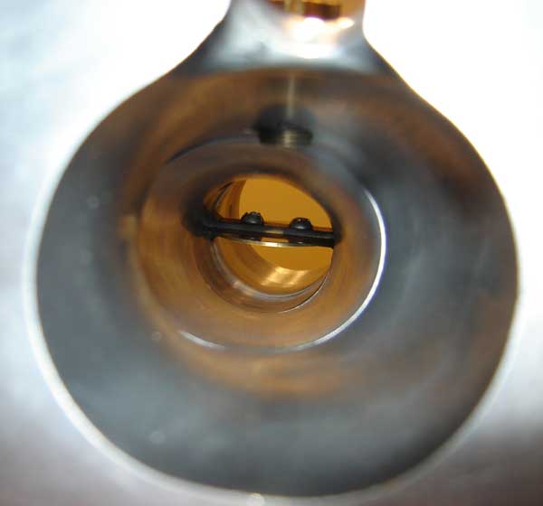
by GhostAccord, on Flickr
Not to be overly defensive of your post, hey I agree, these are just meant to be fun for me. They weren't designed using CAD or a CNC machine so I get what I get.....no harm done! but can you clarify some of the stuff that I asked....thanks
Thanks for the heads up/constructive criticism. Could you tell me by looking at my pics how much fluting....tapper I would require to achieve optimum density with my ITB's?
I think I have the "n" equation covered as my setup is actually larger in diameter than the stock IM and I am using a custom ground cam as you mentioned. But I still don't see what that "n" has to do with ITB's specifically??? My cylinder volume remains the same as it was with my stock IM and just because my cam may be open for a different duration that only means too fill it faster or slower and I'm pretty sure I have more than enough volume to feed it what ever it wants, how ever! In order for you to help me out further you would need to know my cam specs... I can't remember them Right now......
Just to clarify a miss understanding in regards to runner diameter. My ITB's are not single stage(diameter) pipe
I may have been a bit miss leading with my original numbers.My ITB's are 4 stage...+velocity stacks
60mm @ the velocity stacks, to
51mm @ the trumpet, to
46mm @ the throttle plate to
42mm @ the head and down to
34mm @ the valve.
Thanks for your input<TABLE WIDTH="90%" CELLSPACING=0 CELLPADDING=0 ALIGN=CENTER><TR><TD>Quote, originally posted by "Seeds" »</TD></TR><TR><TD CLASS="quote">Edit: Damn, I forgot about the injection points. ITB's work best with multi point injection. The position you have yours at now is good for about the first 3k RPM, a mid runner injection is good till about 3-6.5k RPM, and higher than that you actually want the injector facing into the throat of the ITB's. Chrome does not accommodate multi injectors, so the place you put them at is the best for what you have. If you try moving the injectors up, the fuel will puddle at idle and low RPM because there is not enough velocity at those RPM ranges to keep the fuel suspended, and this causes a lot of other problems.</TD></TR></TABLE>
I don't understand...Why is it that Crome can't account for this...In Crome I have the ability to change any of the fuel maps for any given RPM at any mbar or TPS%. Wouldn't the start up and throttle tip in the individual fuel correction settings help with this puddle problem? It's good that you tell me that Crome won't work but you never got to the why and if Crome won't work what will?
<TABLE WIDTH="90%" CELLSPACING=0 CELLPADDING=0 ALIGN=CENTER><TR><TD>Quote, originally posted by "Seeds" »</TD></TR><TR><TD CLASS="quote">The only other thing that I can see that you may consider doing differently in the future is using mandrel bends on those two out side pipes instead of the sharp bends you got from welding those angled pieces together.</TD></TR></TABLE>
yeah they look pretty bad from the outside but when you get a shot from the inside the fit is actually not quite as bad after I ported them.
This is a shot of the really bent runner on cylinder 1
by GhostAccord, on Flickr
Not to be overly defensive of your post, hey I agree, these are just meant to be fun for me. They weren't designed using CAD or a CNC machine so I get what I get.....no harm done! but can you clarify some of the stuff that I asked....thanks
Last edited by GhostAccord; 03-11-2018 at 07:58 AM.
04-06-2007, 06:42 PM
#29
Honda-Tech Member
Thread Starter
<TABLE WIDTH="90%" CELLSPACING=0 CELLPADDING=0 ALIGN=CENTER><TR><TD>Quote, originally posted by "Turbowa" »</TD></TR><TR><TD CLASS="quote">Thanks for the info </TD></TR></TABLE>
Hey no problem....can you get them cheaper ??? I'm always looking for lower prices on quality stuff, still have rods and pistons to buy for next year.
</TD></TR></TABLE>Hey no problem....can you get them cheaper
??? I'm always looking for lower prices on quality stuff, still have rods and pistons to buy for next year.
04-07-2007, 05:14 AM
#30
Honda-Tech Member
Join Date: May 2006
Location: Texas, United States
Posts: 53
Likes: 0
Received 0 Likes
on
0 Posts
ok... n. Umm, n is the amount of air that the head is able to flow at any one given point. when the valve first opens it will flow n amount of air, as it opens more it flows more air. The amount of air it flows as it opens further is based on the cam grind because the grind on the cam is what controls how far the valve is extended. So the cam grind is opening at this rate which allows this amount of air in by volume. You have to time that amount of air to enter at that valve position. You do this by having the volume of the runner increasing as the the valve position increases. Time per say does not have much to do with it, the engine speed dictates the amount of time it takes for the valve to open and close, but the air is going to rush in just the same.
mathematically it would look like this:
Flow Rate = F
degrees of cam = theta
Available Air = V (for volume)
and the length of the runner = X
F(theta)=V(X) or Flow Rate at theta equals Volume at X
earlier I described n as the volume of air that can enter the cylinder at any given time, this volume of air entering can not exceed the volume able to enter or else not all of it will make it into the cylinder and will cause turbulence and mess up the rest of the flow. If the volume entering is smaller than the maximum you are not filling the cylinder to its potential. In other words it is an exact balance, and for every degree of cam movement you will have a certain amount of air move, so that volume must be available at that X(distance) along the runner, but it also needs not exceed that volume. To get an exact equation for V(X) you have to use a calculus technique called integration on F(theta). In order to have the flow rate you have to have a flow table for your head. What we were doing by saying f(n) is comparing F and V since they are both volumes. I called this volume n, and f simple stands for a function of. So for each degree in cam rotation, the X diameter increases to accommodate for the increase in volume. Essentially what you are doing is taking sections along the length of the runner and making them wider and wider to make that specific section match the volume that is going to be required at that cam degree at which it reaches the port.
Here is the thing, you are accommodating the fact that at the beginning you can only take in so much air, as you move along the cam lobe you can accommodate more and more air. When the air moves along the path toward the port it encounters a smaller diameter tubing, which makes it seem as if it would only allow space for that amount of air, but air is a gas and compresses under pressure, when the initial air is sucked in it causes a vacuum which is pressure so the air compresses to fit that space. You are taking the volume of a circle X+1 and making it fit a circle X which is smaller, but this does not matter, because when it gets into the cylinder it will re-expand to what ever the pressure is in the cylinder at the time. That could take a whole nother explanation, and if you need me to go into it ask, but for now what you are concerned with is that the air made it to the cylinder with out any impedance, and it made it there in the most efficient volume possible.
So what is done is that you take the amount of expansion that is needed in the circle, and making it efficient so that it never is not able to enter the cylinder in the desired volume. As the cam starts to get to the top of the lobe the amount of time it is going to be there is minimal. If you make the throat of the ITB the diameter required for the volume to flow at that specific moment that the valve is completely open you will have 100% volumetric efficiency, and due to the limitations of boring you will not be able to have a pipe that goes from open to close of a valve in one constant function. The continuously larger flow rate of the head starts diminishing at about 50-70% open which if you looked at a graph would stop being a strait line, and start becoming parabolic... seeing as making a parabolic shaped runner is difficult and the gas compression and intake at the velocity stack is compromised by this you only take the runner out to 50-70% of the cam rotation. Since X is the function of Volume, you make the runner X long so that it makes the linearly increasing volume occur up to 50-70 percent of opening. Once again though, you have to look at the flow of the head to see where the numbers start to deviate from the linear equation which should fall between 50-70% open.
Chrome... what is meant by multiple injectors is more than one injector per runner. fuel atomization as better the faster the air is moving, and the more time it has in that fast moving air the better it will atomize. Two problems occur with single point injection. The first one is that if you have the injection point mid runner, you have to either inject fuel till the valve closes, and there is fuel in the air that did not make it to the port before the valve close, and the fuel starts to drop out of suspension, or you end up with air that does not have fuel in it, but are not good. If you have the injector at the base, like you do, then you can simply inject fuel as long as the valve is open, but it does not atomize as well. The solution is generally to stage the injectors. All three injectors start firing upon valve opening, each injector includes the amount of fuel required for the extra volume at that point in the runner. There are two methods of doing this, you can have the mid runner and top injectors simply add fuel for volume that sits at that point in the runner, or you can have the injectors stop firing in order as the fuel from the previous injector reaches it. The latter has far superior atomization, but is extremely difficult to time, and continuously changes with engine speed. Chrome does not allow for multi-point injectors, in fact the only ECU that does that I am aware of is AEM and the model I have dealt with only allows for two point injection, not three which is closer to ideal, and is the preferred number... of course a million point injection would be better as well.
Wow, I did not expect the inside of those bent pipes to look like that, very nice!!!
If you have any more questions please ask. I have been meaning to post this to a DIY ITB thread for quite some time now, and have finally had time In doing so, have decided to do a full write up on the topic, as well as other intake systems... it is an immensely interesting topic, and one that is very rarely considered or implemented in engine builds. The design of these things actually has to accommodate a lot more, these are the initial consideration in the designs, and I want to put all of it into one article. Letting me know what you do not understand will help me clarify that write up as well.
I will try to respond as soon as I can, but unfortunately I will be taking off for the dreaded trip to the in laws here in a short bit, and god only knows what time they will allow me to escape them on Sunday.
04-07-2007, 06:57 AM
#31
Honda-Tech Member
Thread Starter
Thanks Seeds That was very well put and I will take these equations into account when I end up having troubles with these things. Because it is inevitable that I will run into some problems such as you have described and I would have never known what was wrong.
Thanks again for the clarification and I'll probably be hitting you up for more info in the future
Cheers
That was very well put and I will take these equations into account when I end up having troubles with these things. Because it is inevitable that I will run into some problems such as you have described and I would have never known what was wrong.Thanks again for the clarification and I'll probably be hitting you up for more info in the future
Cheers
04-10-2007, 06:06 PM
#33
Honda-Tech Member
Join Date: Apr 2006
Location: Portland, OR, USA
Posts: 486
Likes: 0
Received 0 Likes
on
0 Posts
<TABLE WIDTH="90%" CELLSPACING=0 CELLPADDING=0 ALIGN=CENTER><TR><TD>Quote, originally posted by RUEN96 »</TD></TR><TR><TD CLASS="quote">CAN I PUT A H22 Head ON A F22.....</TD></TR></TABLE>
short answer is: yes
short answer is: yes
04-11-2007, 03:44 AM
#34
H-T Order of Merit
<TABLE WIDTH="90%" CELLSPACING=0 CELLPADDING=0 ALIGN=CENTER><TR><TD>Quote, originally posted by RUEN96 »</TD></TR><TR><TD CLASS="quote">CAN I PUT A H22 Head ON A F22.....</TD></TR></TABLE>
not the place for this question, don't hijack someones thread, it's against the rules.
not the place for this question, don't hijack someones thread, it's against the rules.
04-11-2007, 03:49 AM
#35
H-T Order of Merit
<TABLE WIDTH="90%" CELLSPACING=0 CELLPADDING=0 ALIGN=CENTER><TR><TD>Quote, originally posted by GhostAccord »</TD></TR><TR><TD CLASS="quote">I don't see the big to do with H series heads myself, unless it's for the DOHCs. In that case just swap a complete H series motor and save yourself the trouble</TD></TR></TABLE>
I think the attraction for some people to do the hybrid setup rather than swapping the whole motor is to keep the iron sleeves of the F block which is better for boost and/or forged piston, the H series blocks have FMR sleeves or whatever that material is.
but enough of that, back on topic
I think the attraction for some people to do the hybrid setup rather than swapping the whole motor is to keep the iron sleeves of the F block which is better for boost and/or forged piston, the H series blocks have FMR sleeves or whatever that material is.
but enough of that, back on topic
04-11-2007, 02:06 PM
#36
Member
<TABLE WIDTH="90%" CELLSPACING=0 CELLPADDING=0 ALIGN=CENTER><TR><TD>Quote, originally posted by GhostAccord »</TD></TR><TR><TD CLASS="quote">
Hey no problem....can you get them cheaper ??? I'm always looking for lower prices on quality stuff, still have rods and pistons to buy for next year.
</TD></TR></TABLE>
No I don't think so. I don't sell any parts or any thing like that. I'm looking at going N/A in my F22b2 and looking for prices on head gear. Just boughta used head and am planing on sending the cam to Bisi to have it worked on and will want to get valve train before it goes in. I also want send the head to Endyne to have them clean it up and do some work on at the same time.
Hey no problem....can you get them cheaper
??? I'm always looking for lower prices on quality stuff, still have rods and pistons to buy for next year.</TD></TR></TABLE>
No I don't think so. I don't sell any parts or any thing like that. I'm looking at going N/A in my F22b2 and looking for prices on head gear. Just boughta used head and am planing on sending the cam to Bisi to have it worked on and will want to get valve train before it goes in. I also want send the head to Endyne to have them clean it up and do some work on at the same time.
04-11-2007, 05:33 PM
#37
Honda-Tech Member
Thread Starter
<TABLE WIDTH="90%" CELLSPACING=0 CELLPADDING=0 ALIGN=CENTER><TR><TD>Quote, originally posted by "Turbowa" »</TD></TR><TR><TD CLASS="quote">I'm looking at going N/A in my F22b2</TD></TR></TABLE>I'm going at my head next week to see how I can make it flow for my ITB's. Given the information that Seeds gave me on initial volume and flow rate I'll probably be adding a bit of material to the intake ports on my head and then go from there as to what contours will alow them to flow. We'll have to wait and see once I get them on a flow bench. I'll have more images and updates buy then.
04-13-2007, 12:02 PM
#38
Honda-Tech Member
Thread Starter
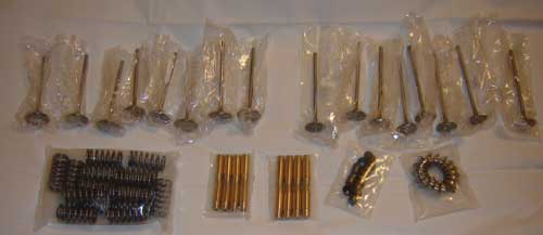
Well I don't get as excited as some over clear plastic bags with red "H's" on them but these parts make my heart beat a bit faster
by GhostAccord, on Flickr
by GhostAccord, on Flickr
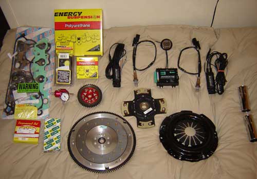
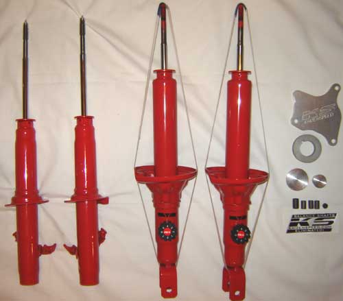
Well I now have all of the gear for my head. This is what was waiting for me down at the ol mailbox today when I came home from work.......ahhhh the mids to highs on this should be pretty sweet!
by GhostAccord, on Flickr
KYB struts and Kaizenspeed balance shaft eliminator kit.....
by GhostAccord, on Flickr
Well here is what I have been working on putting together for the last little while. I didn't want to post pics after each part was blasted and coated so I figured I would post them all at once.
Front beam and radius rods
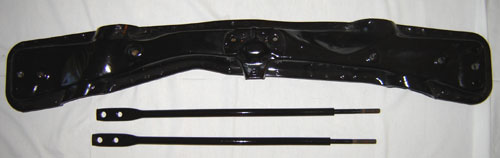
by GhostAccord, on Flickr
Center Beam
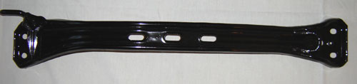
by GhostAccord, on Flickr
Rear Beam
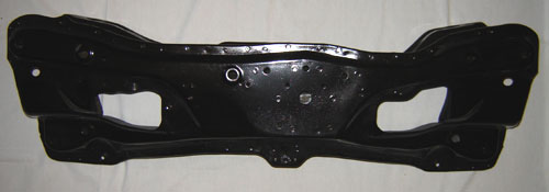
by GhostAccord, on Flickr
Rack and tie rod ends
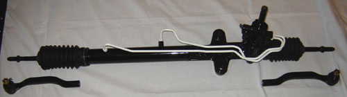
by GhostAccord, on Flickr
Front suspension - should go nice with my red KYB's
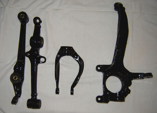
by GhostAccord, on Flickr
Rear suspension
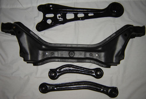
by GhostAccord, on Flickr
Gloss Black Oil pan to go with my gloss white VC....
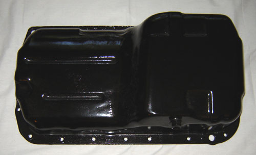
by GhostAccord, on Flickr
I got tired of cleaning and coating my suspension so I took a day to do my V-Cover instead.
Simple Green works great for getting rid of grease and dirt. This was after a 20min soak in hot water and SG. A light scrub with a dish cleaning brush and then dried with a shop/bath towel. My wife is starting to ask were all the bath towels are going.....lol j/k
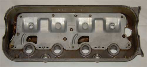
by GhostAccord, on Flickr
Stripped using off the shelf home depot paint stripper. Applied and scrubbed off using a coarse scotchbright pad. No time at all to strip this little guy. After I was finished with the stripper I put it in the varsol bath for about 10min.
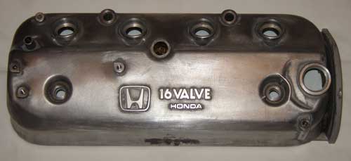
by GhostAccord, on Flickr
Viola
by GhostAccord, on Flickr
Had to take the extra 20 minutes to file and polish the lettering.......
Just wanted to give a shout out and big thank you to Chris and his team over at Xenocron for some outstanding customer service. He was quick to inform me that the rad I had ordered was on back order. Much appreciated. Then he arranged to have the order shipped right to my door saving a lot of time and cross boarder red tape BS. Sounds simple enough but not enough vendors care enough to contact customers anymore. I didn't even request a rush or anything, I ordered it and didn't really care when it shipped.
Huge thanks Chris. This type of customer service is what will keep me shopping at your E-Store.
Updates
Well as mentioned above I got two shipment in this week.
My aluminum half rad (Xenocron) fuel, brake and oil -AN fittings (Summit). Also has good customer service and very fast shipping considering they are using the USPS.
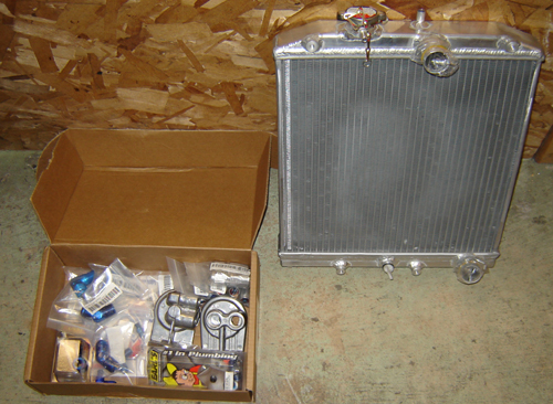
by GhostAccord, on Flickr
Cheers
by GhostAccord, on Flickr
by GhostAccord, on Flickr
Well I now have all of the gear for my head. This is what was waiting for me down at the ol mailbox today when I came home from work.......ahhhh the mids to highs on this should be pretty sweet!
by GhostAccord, on Flickr
KYB struts and Kaizenspeed balance shaft eliminator kit.....
by GhostAccord, on Flickr
Well here is what I have been working on putting together for the last little while. I didn't want to post pics after each part was blasted and coated so I figured I would post them all at once.
Front beam and radius rods
by GhostAccord, on Flickr
Center Beam
by GhostAccord, on Flickr
Rear Beam
by GhostAccord, on Flickr
Rack and tie rod ends
by GhostAccord, on Flickr
Front suspension - should go nice with my red KYB's
by GhostAccord, on Flickr
Rear suspension
by GhostAccord, on Flickr
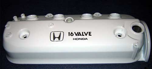
Gloss Black Oil pan to go with my gloss white VC....
by GhostAccord, on Flickr
I got tired of cleaning and coating my suspension so I took a day to do my V-Cover instead.
Simple Green works great for getting rid of grease and dirt. This was after a 20min soak in hot water and SG. A light scrub with a dish cleaning brush and then dried with a shop/bath towel. My wife is starting to ask were all the bath towels are going.....lol j/k
by GhostAccord, on Flickr
Stripped using off the shelf home depot paint stripper. Applied and scrubbed off using a coarse scotchbright pad. No time at all to strip this little guy. After I was finished with the stripper I put it in the varsol bath for about 10min.
by GhostAccord, on Flickr
Viola
by GhostAccord, on Flickr
Had to take the extra 20 minutes to file and polish the lettering.......
Just wanted to give a shout out and big thank you to Chris and his team over at Xenocron for some outstanding customer service. He was quick to inform me that the rad I had ordered was on back order. Much appreciated. Then he arranged to have the order shipped right to my door saving a lot of time and cross boarder red tape BS. Sounds simple enough but not enough vendors care enough to contact customers anymore. I didn't even request a rush or anything, I ordered it and didn't really care when it shipped.
Huge thanks Chris. This type of customer service is what will keep me shopping at your E-Store.
Updates
Well as mentioned above I got two shipment in this week.
My aluminum half rad (Xenocron) fuel, brake and oil -AN fittings (Summit). Also has good customer service and very fast shipping considering they are using the USPS.
by GhostAccord, on Flickr
Cheers
Last edited by GhostAccord; 03-11-2018 at 09:51 AM.
04-15-2007, 01:17 PM
#39
Honda-Tech Member
Thread Starter
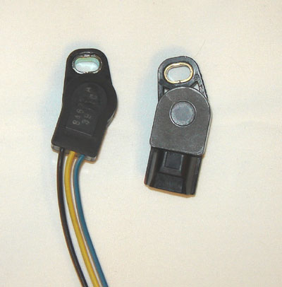
There was another post on H-T asking about what Throttle Position Sensor (TPS) to use on DIY ITB's. I just finished testing my GSXR to F22B2 OBD2 TPS setup and everything works fine.
Here is how I did it:
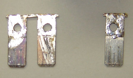
I am using the stock GSXR Secondary TPS as it already has three wires ready to go. The primary GSXR TPS does not, it has a male connector on it,
Secondary TPS on the left, Primary TPS on the right.
by GhostAccord, on Flickr
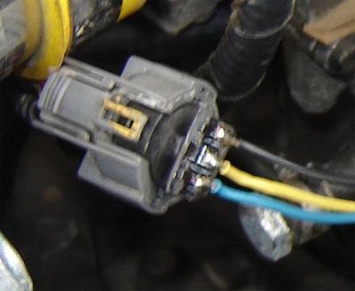
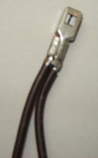
I took an old Civic TPS and cut the guts out of it and exposed the connectors on the inside. I then cut the rest of the old TPS housing off. Leaving me with my newly created male connector. After soldering the three wires in there proper positions Sig/Gnd/Ref I had my GSXR to Honda TPS conversion ready for testing....
Close-up of the altered Civic TPS hooked into my OBD2 wiring harness.
by GhostAccord, on Flickr
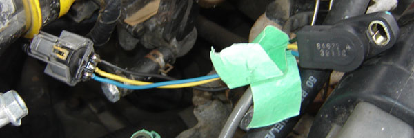
New TPS and harness connected for testing, I used a screw driver to turn the GSXR TPS to simulate WOT.
by GhostAccord, on Flickr
I ran all of the standard Honda Voltmeter tests to confirm that the TPS was working correctly. At this time I was also able to record the actual voltage range for my new TPS so I can add them into my ITB TPS settings in Crome. I don't have any actual images of the readings as I only have two hands and I was flying solo today. Here are the readings that I read: 1.13v @ CT and 4.89v @ WOT.
anywho I still only have to plug those numbers into Crome ITB Tools.
NOTE:
If you use the primary GSXR TPS the voltages are pretty much spot on with the Honda specs. 0.46 @ CT and 4.47 @ WOT
Next update will be my Stock to Accel CD Ignition external Coil conversion harness and connector. Yeah I know what everyone says about aftermarket coils but guess what.....I had this one laying around the house and I like the looks of it
Here is how I did it:
I am using the stock GSXR Secondary TPS as it already has three wires ready to go. The primary GSXR TPS does not, it has a male connector on it,
Secondary TPS on the left, Primary TPS on the right.
by GhostAccord, on Flickr
I took an old Civic TPS and cut the guts out of it and exposed the connectors on the inside. I then cut the rest of the old TPS housing off. Leaving me with my newly created male connector. After soldering the three wires in there proper positions Sig/Gnd/Ref I had my GSXR to Honda TPS conversion ready for testing....
Close-up of the altered Civic TPS hooked into my OBD2 wiring harness.
by GhostAccord, on Flickr
New TPS and harness connected for testing, I used a screw driver to turn the GSXR TPS to simulate WOT.
by GhostAccord, on Flickr
I ran all of the standard Honda Voltmeter tests to confirm that the TPS was working correctly. At this time I was also able to record the actual voltage range for my new TPS so I can add them into my ITB TPS settings in Crome. I don't have any actual images of the readings as I only have two hands and I was flying solo today. Here are the readings that I read: 1.13v @ CT and 4.89v @ WOT.
anywho I still only have to plug those numbers into Crome ITB Tools.
NOTE:
If you use the primary GSXR TPS the voltages are pretty much spot on with the Honda specs. 0.46 @ CT and 4.47 @ WOT
Next update will be my Stock to Accel CD Ignition external Coil conversion harness and connector. Yeah I know what everyone says about aftermarket coils but guess what.....I had this one laying around the house and I like the looks of it
Last edited by GhostAccord; 03-11-2018 at 10:03 AM.
04-22-2007, 08:15 AM
#41
Honda-Tech Member
Thread Starter
It seems like everyone on this site hates these things. I would have to take a guess and say that my stock coil must have been on it's last legs because WOOOOTTT! What a difference this Accel Coil made for my car......Fired right up, no hesitation, throttle response was right F'n there, no hesitation at all. Now with that being said I also have an upgraded cap, rotor, Accel 8.8mm ferro spiral core wires and NGK ZFR5FIX-11 Iridium IX spark plugs
by GhostAccord, on Flickr
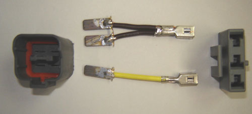
Here is how I made my conversion harness for my Accel CD E-Core Ignition Coil Pt# 140019. This harness is for an F22B2 external coil. You will have to do an internal to external wire up to be able to do this. I didn't have to
Do we have to put disclaimers on our DIY write-ups? Oh well whatever, if you have no clue what your doing don't do this you can F#@k your Shyte Up Bad! There disclaimer done!
Ensure that you are familiar with your ignition system before attempting this conversion.
As always when working on any part of your vehicles electrical system disconnect the cable from your negative battery terminal. Caution: If you have the stock Honda radio still installed in your vehicle it is equipped with an anti-theft system. Make sure you have the activation code before attempting this. Or you'll be paying the dealer a visit to enable your radio. $$$ you don't need to spend.
First I had to hack apart an old Stock F22B2 coil that I had laying around very easy to do..hacksaw 5 min tops.
Routered the stock connector so I could solder the coil wires to the inside contacts.
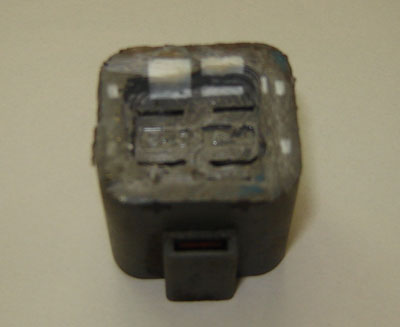
by GhostAccord, on Flickr
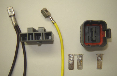
I pulled out the stock contacts from the connector and drilled holes so that I could do a pull through solder.
by GhostAccord, on Flickr
Now on the Accel side of things the coil only has 1 + terminal and one - terminal and the stock ignition has 2 + & 1 -. I had to improvise and solder another wire to the Accel + wire connector. That is all that has to be done on the Accel side of things.
by GhostAccord, on Flickr
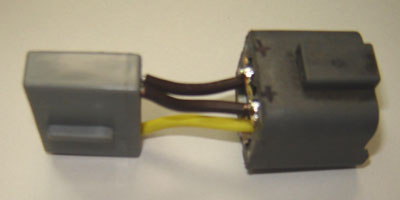
Here are all the parts together up to this point.
by GhostAccord, on Flickr
Now all there is to do is shorten and solder the wires as shown below.
by GhostAccord, on Flickr
Note: insure that you make note of where the two positive and the negative contacts are situated. I marked my connector with a black marker +/+ on the positive side & - on the negative side. Just wanted to make this clear you can see my + + on the following image.
Note: There is a post on here that I think may be wrong but I'm not 100% as he is using the MSD blaster ignition. He mentions that the two wires are supposed to go to the negative terminal......do not do this with the Accel coil....External Honda coils have two positive connections YEL & BLK/YEL and 1 negative connection GREEN.
by GhostAccord, on Flickr
After placing the wires into the connector your all set for water proofing. I used a piece of tape wrapped around the connector to creat a sort of form for the silicone. I used everyday kitchen and bath clear silicone that you can pick up at any hardware store.
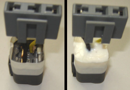
by GhostAccord, on Flickr
Silicone is a good insulator in a pinch, I don't have access to liquid Teflon....or a plastic injection system, these would be more professional and permanent choices.
by GhostAccord, on Flickr
Here is how I made my conversion harness for my Accel CD E-Core Ignition Coil Pt# 140019. This harness is for an F22B2 external coil. You will have to do an internal to external wire up to be able to do this. I didn't have to
Do we have to put disclaimers on our DIY write-ups? Oh well whatever, if you have no clue what your doing don't do this you can F#@k your Shyte Up Bad! There disclaimer done!
Ensure that you are familiar with your ignition system before attempting this conversion.
As always when working on any part of your vehicles electrical system disconnect the cable from your negative battery terminal. Caution: If you have the stock Honda radio still installed in your vehicle it is equipped with an anti-theft system. Make sure you have the activation code before attempting this. Or you'll be paying the dealer a visit to enable your radio. $$$ you don't need to spend.
First I had to hack apart an old Stock F22B2 coil that I had laying around very easy to do..hacksaw 5 min tops.
Routered the stock connector so I could solder the coil wires to the inside contacts.
by GhostAccord, on Flickr
I pulled out the stock contacts from the connector and drilled holes so that I could do a pull through solder.
by GhostAccord, on Flickr
Now on the Accel side of things the coil only has 1 + terminal and one - terminal and the stock ignition has 2 + & 1 -. I had to improvise and solder another wire to the Accel + wire connector. That is all that has to be done on the Accel side of things.
by GhostAccord, on Flickr
Here are all the parts together up to this point.
by GhostAccord, on Flickr
Now all there is to do is shorten and solder the wires as shown below.
by GhostAccord, on Flickr
Note: insure that you make note of where the two positive and the negative contacts are situated. I marked my connector with a black marker +/+ on the positive side & - on the negative side. Just wanted to make this clear
you can see my + + on the following image.Note: There is a post on here that I think may be wrong but I'm not 100% as he is using the MSD blaster ignition. He mentions that the two wires are supposed to go to the negative terminal......do not do this with the Accel coil....External Honda coils have two positive connections YEL & BLK/YEL and 1 negative connection GREEN.
by GhostAccord, on Flickr
After placing the wires into the connector your all set for water proofing. I used a piece of tape wrapped around the connector to creat a sort of form for the silicone. I used everyday kitchen and bath clear silicone that you can pick up at any hardware store.
by GhostAccord, on Flickr
Silicone is a good insulator in a pinch, I don't have access to liquid Teflon....or a plastic injection system, these would be more professional and permanent choices.
Last edited by GhostAccord; 03-11-2018 at 10:19 AM.
05-21-2007, 01:00 PM
#43
Honda-Tech Member
Thread Starter
All of the debates on holmoltz (spelling, don't care) resonance tuning intakmanifolds has turned me in yet another direction with this project. No I am not giving up . I have decided to use the factory GSX-R 1000 STVS (Secondary Throttle Valve System) to create a type of variable length runner / secondary air flow control. I am in the process right now of trying to bench test a control system to have them work as they would have on the bike. I do not want to buy a Suzuki GSX-R ECM and wire it into my Honda sensors, major head ache.
I have chosen to use the Honda IAB controls for them. I have run into a bit of a snag with the fact that I am using Crome and it does not suport ITB's with it's P72 ROM yet. I am going to see if there is another output that i can use with the P30 ROM that will operate the IAB's. Maybe using the VTEC outputs will work????? not sure I will post my results when I get them.
April 09 Update
I have not been through my own thread much lately and totally forgot about this P30 ROM query until d112crzy brought it too my attention. Thanks again Boss
Answer;
The newer version of Crome Pro with Gold ROM does allow for the use of ITB's with IAB support. As does eCtune. I have since discovered both and have my secondary throttle system figured out. I am still not 100% whether or not they will make any difference. i won't know that until I get it on the dyno.
Here is what I have been up too while I wait for my garage. My P75 A01 automatic non VTEC ECU after it's full conversion to a P75 A01 with VTEC, IAB, data logging, and socketed ECU. Got the brains now to get working on the brawn!
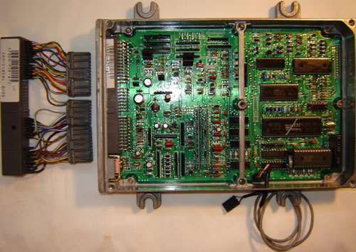
by GhostAccord, on Flickr
. I have decided to use the factory GSX-R 1000 STVS (Secondary Throttle Valve System) to create a type of variable length runner / secondary air flow control. I am in the process right now of trying to bench test a control system to have them work as they would have on the bike. I do not want to buy a Suzuki GSX-R ECM and wire it into my Honda sensors, major head ache.I have chosen to use the Honda IAB controls for them. I have run into a bit of a snag with the fact that I am using Crome and it does not suport ITB's with it's P72 ROM yet. I am going to see if there is another output that i can use with the P30 ROM that will operate the IAB's. Maybe using the VTEC outputs will work????? not sure I will post my results when I get them.
April 09 Update
I have not been through my own thread much lately and totally forgot about this P30 ROM query until d112crzy brought it too my attention. Thanks again Boss
Answer;
The newer version of Crome Pro with Gold ROM does allow for the use of ITB's with IAB support. As does eCtune. I have since discovered both and have my secondary throttle system figured out. I am still not 100% whether or not they will make any difference. i won't know that until I get it on the dyno.
Here is what I have been up too while I wait for my garage. My P75 A01 automatic non VTEC ECU after it's full conversion to a P75 A01 with VTEC, IAB, data logging, and socketed ECU. Got the brains now to get working on the brawn!
by GhostAccord, on Flickr
Last edited by GhostAccord; 03-11-2018 at 10:40 AM.
02-10-2008, 05:49 PM
#45
Honda-Tech Member
Thread Starter
Update,
Unfortunately they are still sitting on my work bench along with all of the parts that I have bought over the past year. It's frustrating to look at the pile of parts every day but my garage is still under construction and my car is under about 6" of snow as we speak. I plan on getting my car into my garage and start ripping it apart around the 1st of March. All the parts are waiting so I should have some quick moving updates then.
Unfortunately they are still sitting on my work bench along with all of the parts that I have bought over the past year. It's frustrating to look at the pile of parts every day but my garage is still under construction and my car is under about 6" of snow as we speak. I plan on getting my car into my garage and start ripping it apart around the 1st of March. All the parts are waiting so I should have some quick moving updates then.
02-11-2008, 03:14 PM
#46
<TABLE WIDTH="90%" CELLSPACING=0 CELLPADDING=0 ALIGN=CENTER><TR><TD>Quote, originally posted by GhostAccord »</TD></TR><TR><TD CLASS="quote">Update,
Unfortunately they are still sitting on my work bench along with all of the parts that I have bought over the past year. It's frustrating to look at the pile of parts every day but my garage is still under construction and my car is under about 6" of snow as we speak. I plan on getting my car into my garage and start ripping it apart around the 1st of March. All the parts are waiting so I should have some quick moving updates then.
</TD></TR></TABLE>
nice cant wait to see it
Unfortunately they are still sitting on my work bench along with all of the parts that I have bought over the past year. It's frustrating to look at the pile of parts every day but my garage is still under construction and my car is under about 6" of snow as we speak. I plan on getting my car into my garage and start ripping it apart around the 1st of March. All the parts are waiting so I should have some quick moving updates then.
</TD></TR></TABLE>
nice
cant wait to see it
02-21-2008, 07:12 PM
#47
Junior Member
Join Date: Dec 2007
Location: Earth
Posts: 165
Likes: 0
Received 0 Likes
on
0 Posts
<TABLE WIDTH="90%" CELLSPACING=0 CELLPADDING=0 ALIGN=CENTER><TR><TD>Quote, originally posted by 01_CLtypeS »</TD></TR><TR><TD CLASS="quote">nice cant wait to see it </TD></TR></TABLE>
x2
cant wait to see it </TD></TR></TABLE>x2
03-24-2008, 02:29 PM
#49
i plan on doing ITB's and this thread has helped me out ALOT thank you
can't wait to see your whip btw!
can't wait to see your whip btw!
03-31-2008, 03:09 PM
#50
Honda-Tech Member
Thread Starter
Well I got my fair lady in out of the cold this weekend and spent a few hors tearing into her. I got as far as to test fit the ITB's and guess what......
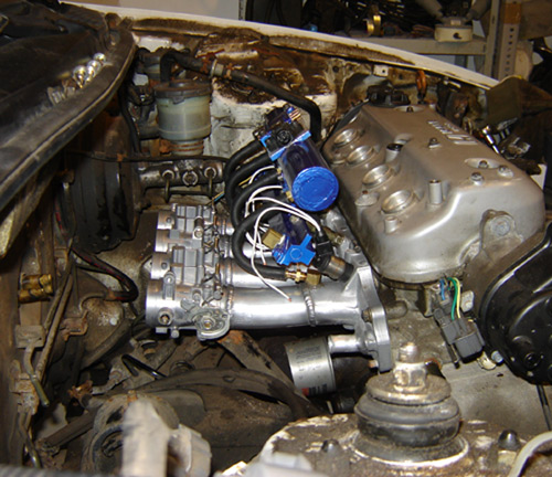
by GhostAccord, on Flickr
They fit with room to spare. I test fit the air box and it fits as well. It is a bit tight but after I do the brake and clutch line tuck she'll be good to go!
I'll keep the updates coming as I get more done.
Here are a few just for starters.
Got rid of some unnecessary items
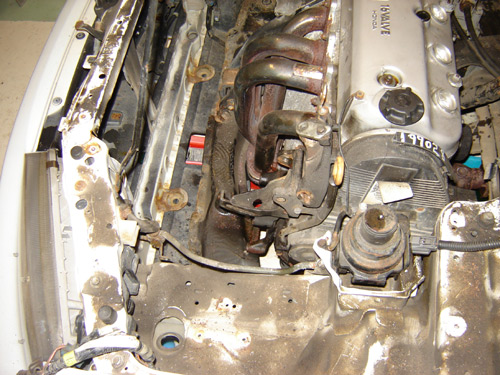
by GhostAccord, on Flickr
Say good bye to the old power steering and AC.
Lots of room...oh wait the rad and fans have to go back.....
by GhostAccord, on Flickr
Looks like I'm going to need a new rad....
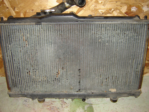
by GhostAccord, on Flickr
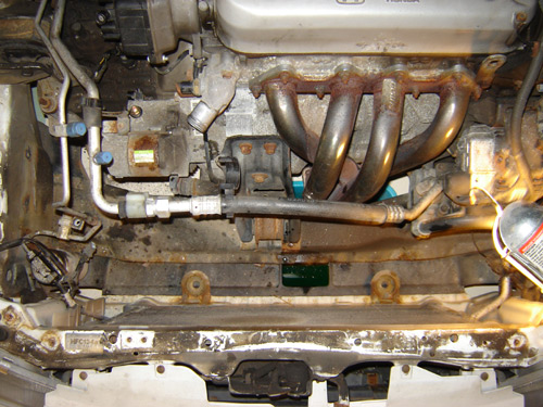
Other than that there is not too much rust or broken stuff so far..... knock on wood
by GhostAccord, on Flickr
They fit with room to spare. I test fit the air box and it fits as well. It is a bit tight but after I do the brake and clutch line tuck she'll be good to go!
I'll keep the updates coming as I get more done.
Here are a few just for starters.
Got rid of some unnecessary items
by GhostAccord, on Flickr
Say good bye to the old power steering and AC.
Lots of room...oh wait the rad and fans have to go back.....
by GhostAccord, on Flickr
Looks like I'm going to need a new rad....
by GhostAccord, on Flickr
Other than that there is not too much rust or broken stuff so far..... knock on wood
Last edited by GhostAccord; 03-11-2018 at 10:53 AM.