

Wire Tuck

Thread Starter
Honda-Tech Member
Joined: Apr 2006
Posts: 1,683
Likes: 2
From: Columbus, OH
If **** talking gets outta hand, this is comin right back down.
SUPRISE!
This isn't another thread asking about them, but rather one explaining them a bit more!
Bet ya didn't expect that!
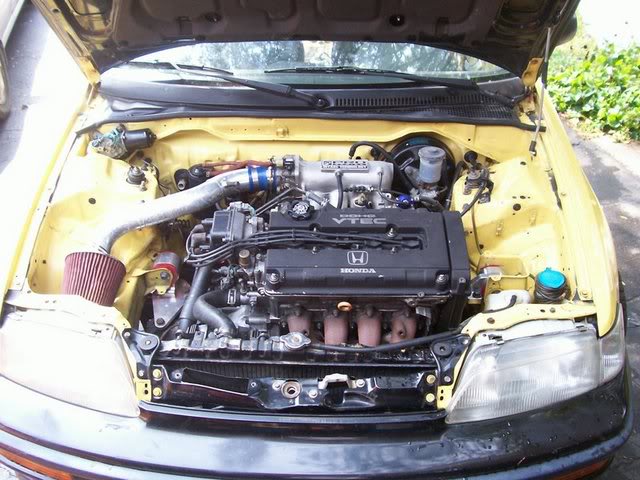
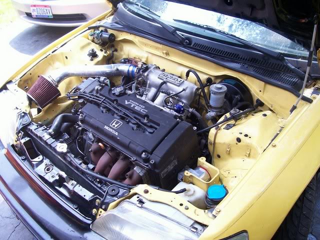
Now, the car: 1988 CRX SI
The Engine: B18C1 OBD1
-Things Specific to this project:
-Only running one 4wire o2.
-No Knock Sensor
-No IAB's (I have S2 IM)
-No Fan Switch plug included as I dont have one at the moment.
Now since I have a slightly custom setup for my wiring, there are going to be some things different between what I'm doing, and what you might want to do.
It's not that hard, so if there are additional wires you have, that I dont, that need included: just figure whether they need extended, then tuck them appropriately.
If I'm wiring things you don't have (Vtec stuff) just ignore it.
And as a general starting point for this, my instructions are going as if you have your front bumper, fenders, and ecu cover removed.
A tip also, never do this w/o the engine in the car. You need to test fit everything to make sure everything has proper length.
Another tip, if possible, do this w/o the radiator installed, the hoses REALLY get in the way....
ONE more tip...Don't completely wrap things until your 100% CERTAIN of them (I.E. your tuck is done except the final wrap) keep it wrapped once every 4 inches or so to keep wires together, but dont fully wrap in case you need to make alterations.
Ok, so first things first, easiest place to start:
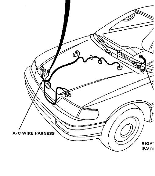
<u>AC WIRING</u>
If your running AC, skip this.
If not, get rid of this wiring if you havent already. It's really simple to tell the AC wiring from Headlight and other wiring b/c it's all in one strand, and all enters the cockpit at one point, in the upper left of the firewall.
Here's the CRX Manual's Diagram of the AC Wiring:
Now here's one of the actual wiring, all removed:
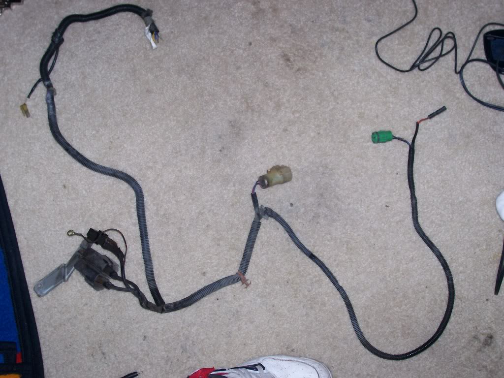
Like I said, it all goes into one spot. Unless you specifically want to maintain the wires, cut them at the firewall, and unplug them under the dash (pictured below) and pull the remaining wire through the dash and its outta there!
Congrats, your free of AC wiring in the engine bay!
<u>PASSENGERSIDE TUCK </u>
So this sides got all the major ****. Fuse Box, big 14 Pin connector, etc. all the good stuff that makes your engine bay so cluttered you go to these lengths to free up some space!
-Start off by unplugging all your headlights if you havent, aswell as the Windshield Wiper Motor, Fuse Box connections, etc.
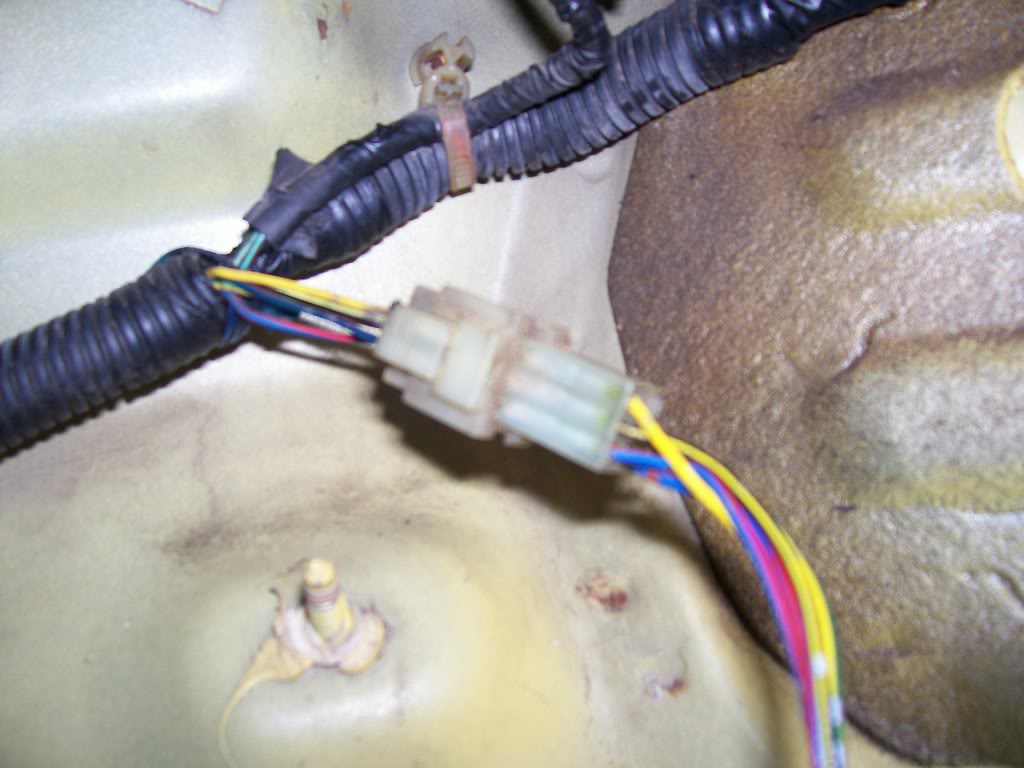
Here's a pic of the Fuse Box wiring undone:
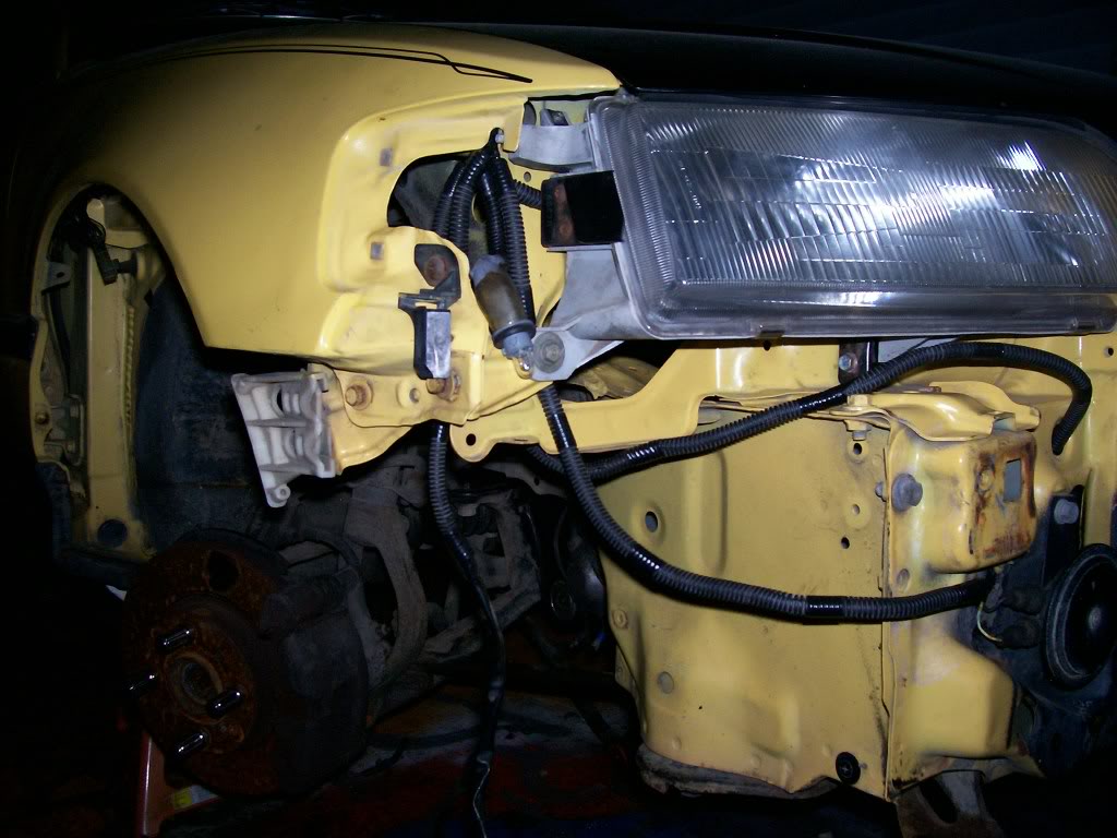
And a pic of the wires from the Headlight Loom that cross into the fuse box/14 pin connector wiring. These will eventually have to be extended, or however you do it as a couple of them are just grounds:
-Now it's really simple: Just unplug everything on this side, and shove all the wiring and connectors into the cockpit.
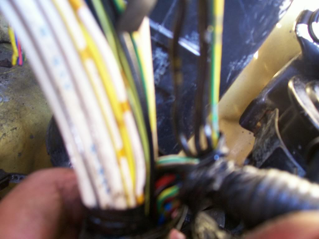
When you do so, leave ALL the engine connections connected. The only one's you'll have to disconnect to move this wiring are: The Map Sensor and the plug next to it, the starter wire (black with white stripe) all the rest will/should reach.
-When you shove it all in, it comes in in 2 bundles:
Bunch 1.The wiring that <u>WENT</u> into the engine bay.
This wiring <u>USED</u> to go INTO the bay. Now it doesn't
Bunch 2.The wiring that GOES TO THE ENGINE, and connnects the above mentioned wiring (Bunch 1)
Here are pictures of what it looks like with Bunch 1 pulled into the Cockpit:
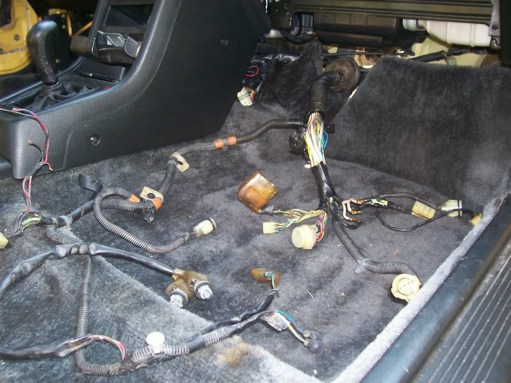
Now on Bunch 1, all the connectors/things brought into the Cockpit can stay there EXCEPT: The Map Sensor and the plug next to it. I dont know what the plug next to it does, but I dont need it as I dont use the Stock Map Sensor location, as my S2 Intake Manifold has one on it. So in my case, I only need to run the Map Sensor BACK into the Engine Bay, you may need to do the other plug aswell. To run the Map Sensor back in there, just split the loom and fish the 3 wires for it out of the sea of other wires, and run it back into the bay.
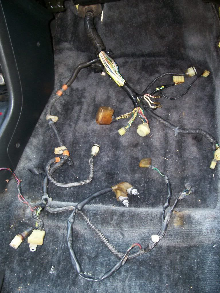
Now there's a Dust Boot that was on Bunch 1 that went into the Engine bay, that kept **** out of the **** pit. It was important to me to maintain this, so I could put it on Bunch 2, the bunch that is now going into the Engine bay, so to continue keeping **** out of the cockpit. So I just depinned the wires where needed and strategically fit it over the plugs and got it off. While doing this, I seperated each strand of wires from the giant Bunch. That way, when I go to shorten them up, it'll be easy to do it without getting confused. Here's a pic of them all seperated and bundled:
Once you've done this, all there is to do is run the Headlight wiring through the fender wall. That is pretty much self explanatory, you'll have to extend a few wires and depin some plugs but you'll get it. I haven't done it yet so I don't have pics, but I will tommorow. For now if you need to see what I'm talkin about, the places to route the wires through are pictured in the other Wire Tuck how to's.
<u>ENGINE WIRING</u>
Now for the fun part. This is probably the most complicated and tedious part of the tuck. So lets start out easy:
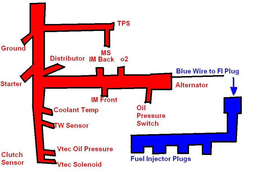
For reference purposes, this is a drawing of what your Engine wiring harness looks like FROM THE FACTORY:
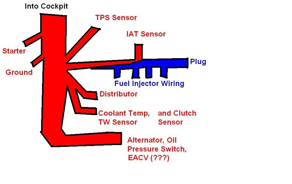
<u>Fuel Injector Wiring </u> - The FI Wiring is seperate from the rest of the engine's wiring (which it is taped into). Now I'm OBD1, so now FI Resistor Box. But I didn't just solder the wires together, I repined the OBD1 Injector wires into their proper spots on the 6pin connector they should go into, that connects on the Driverside.
Either way, OBD0 or 1, your injector wiring is seperate, and I recomend seperating it.
Here's a pic of it seperated and loomed up. Notice the 6 pin connector on the end?
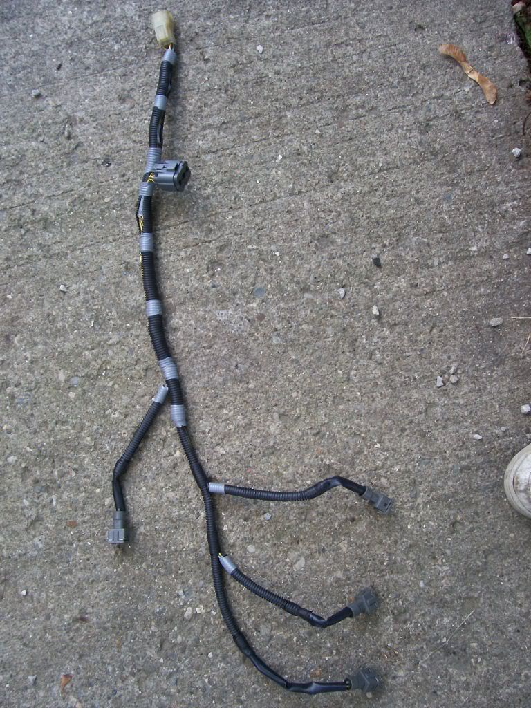
IMPORTANT: There is a BLUE wire in the 6 pin connector. This wire IS part of the engine wiring harness. De pin it, and it will eventually be ran through the engine harness and out by the Alternator, to meet the 6pin connector and plug in this will be detailed momentarily.
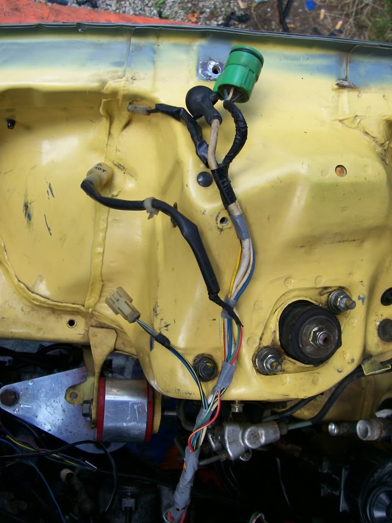
Now it's time for the majority of the wiring. This is again pretty self explanatory:
Based on where the wires are headed, un-loom them, bunch them together properly, and tape them as you go. Remember when doing this the idea is to have as little wire as possible showing, so try to keep things in the FEWEST number of looms as possible, aswell as angling the wire in the way you'd want it permanently hidden.
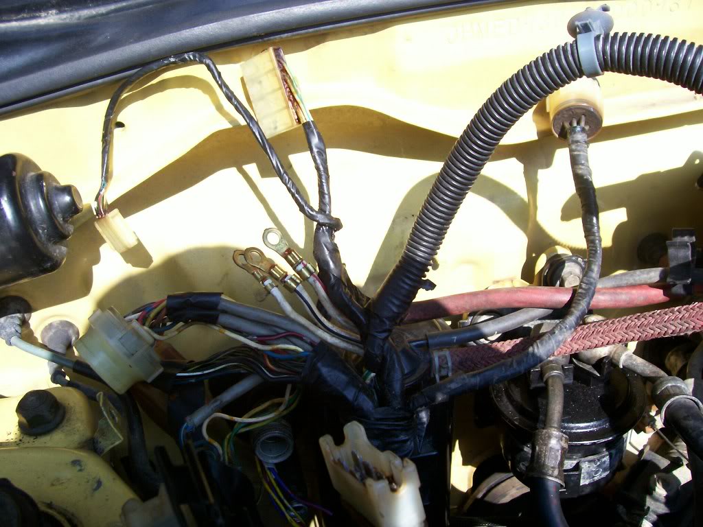
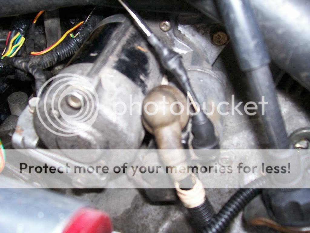
The only wire that'll need extended is the Starter Wire (Black with White Stripe) Pictured below (connecting to the starter on the right)
I kept it simple: 1 loom for the engine connections on the rear and IM, one loom for the TPS and MS, and one for the Coolant Temp, TW Sensor and Vtec plugs. I had a RyWire subharness but I just integrated it into the wiring: vtec plugs in one loom, and ran the o2 wiring in the Rear loom.
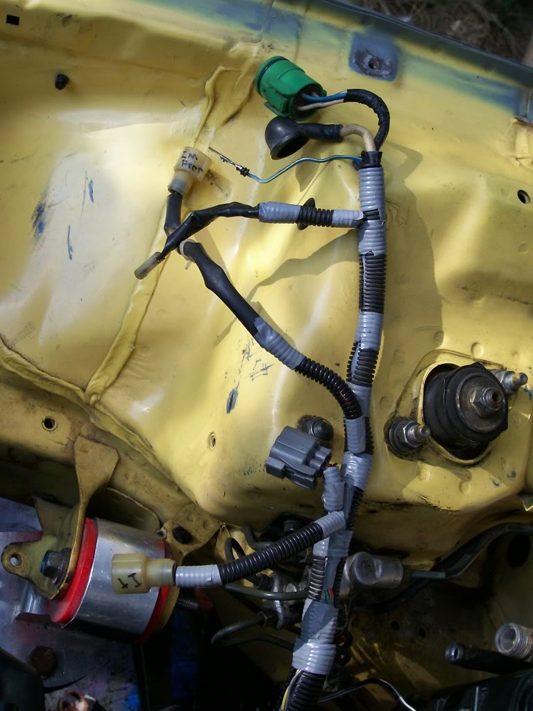
Here's a pic of the looms taped together that would eventually be the rear loom, in my test fit of how I'd run them as one. As you can see, I just got them situated properly and used little bands on tape to mark where they'd end up eventually.
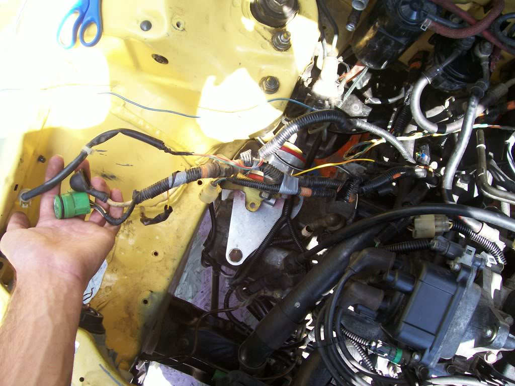
Here's a pic of them wired together the way they'd end up:
And one of them finalized and loomed up:
I didn't take pics of the looming process of the other 2 looms of the Engine Wiring b/c their so simple and self explanatory, I mean their all RIGHT THERE, you just loom them and bundle the wires, simple as that.
So now you should have your wiring for the engine minimalized and tucked to a decent degree. If it's not perfect no biggie, you can always alter it in the future. When doing something like this for the first time, trial and error is key.
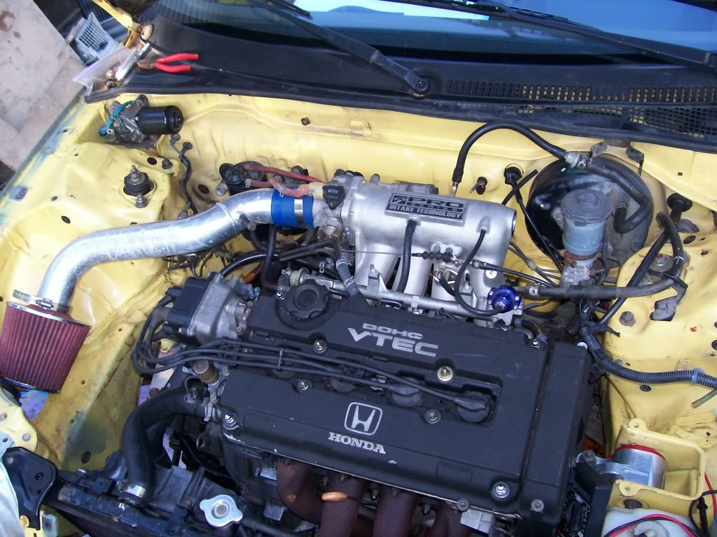
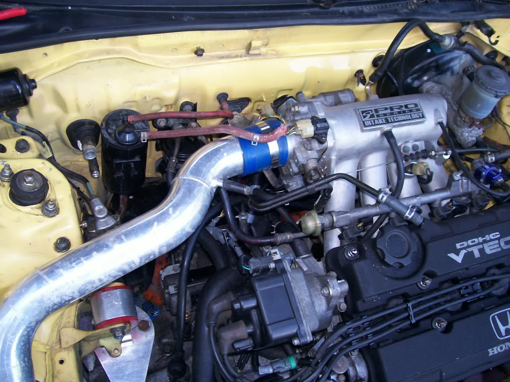
Here's a pic of how I wired everything engine related together, and a few shots of the FI Wiring and Engine Bay (please keep in mind this is mid tuck):
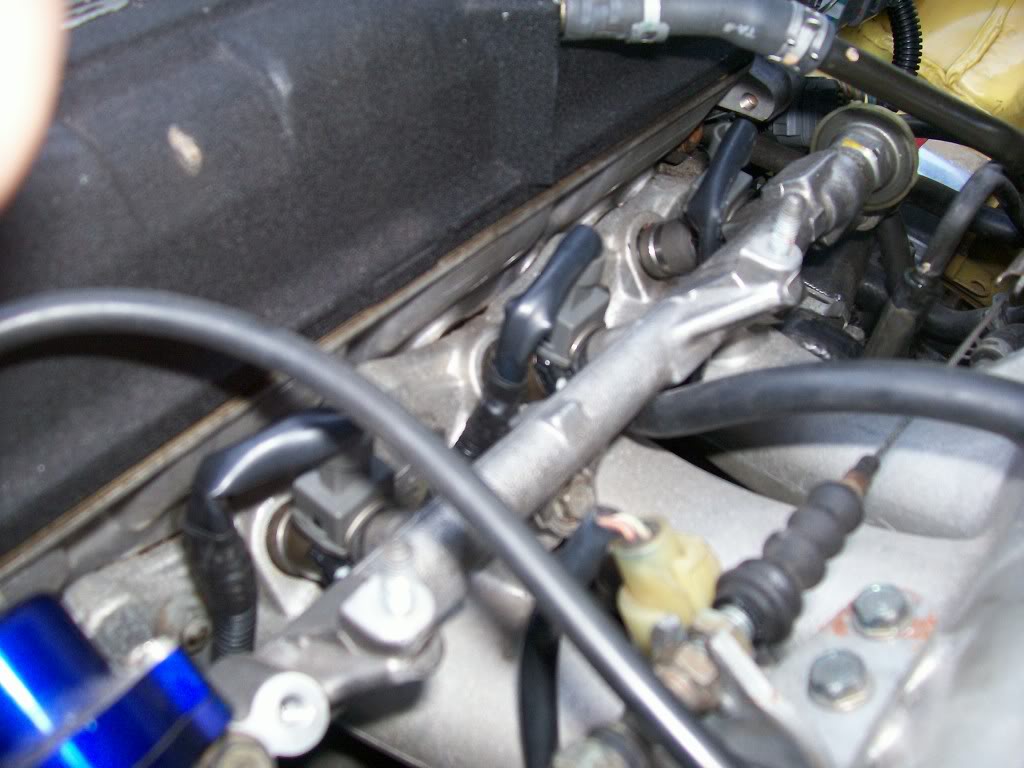
Sorry if the pictures suck or you think this whole thread does.....just thought the basic principles of what I did would be applicable to everyone, and I wanted to try and contribute to our community!
Will have the 2nd half of the write up on here shortly!
EDIT: I wanna take a second to thank EF8KID, along with Magick211 and any others who have made wire tuck how to's in the past. Obviously this wouldn't be goin down without their contributions. Also, a major TY to CRXBart, for had he not taught me how to depin, I'd be knee deep in solder
Modified by G0crxG0 at 10:42 PM 7/6/2006
Second post
<u>Passengerside Wiring through Fenders:</u>
So you've got your wiring in the cockpit and your ready to run the wiring throught the Fenders. Excellent, Great, Grand, Wonderful!
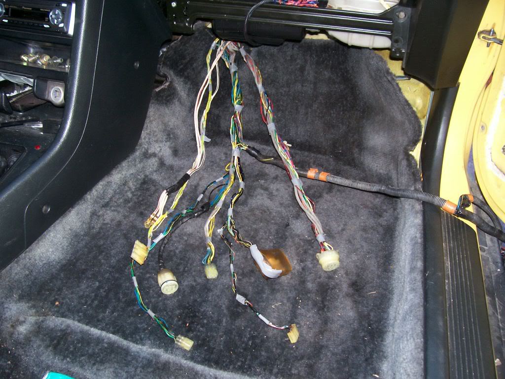
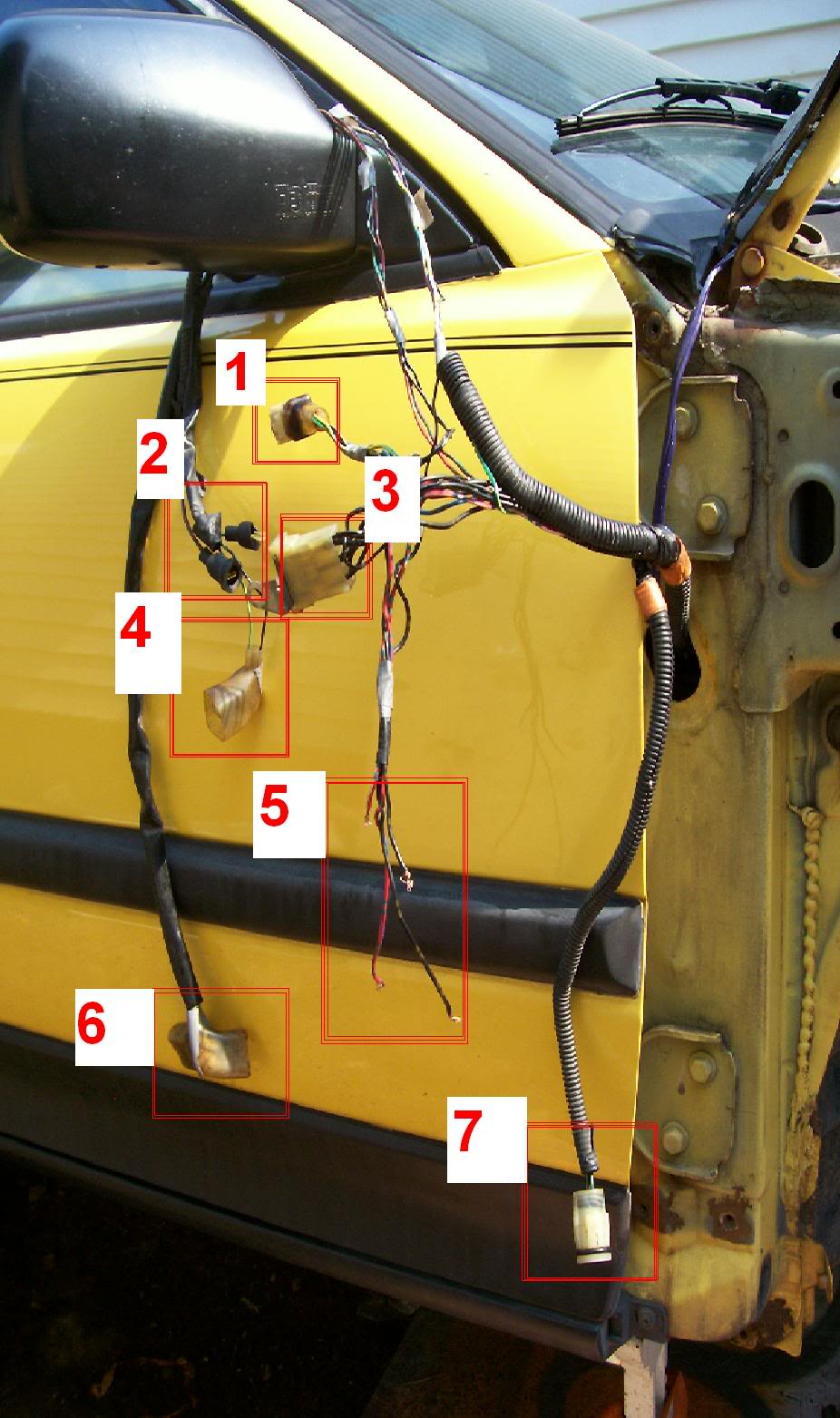
So here's what we're running through there, by number and pictured below (NOTE* - The Windshield wiper needs ran through here too, but is not pictured do to my ******* up!)
1. Radiator Fan Relay
2. Horn Buttons
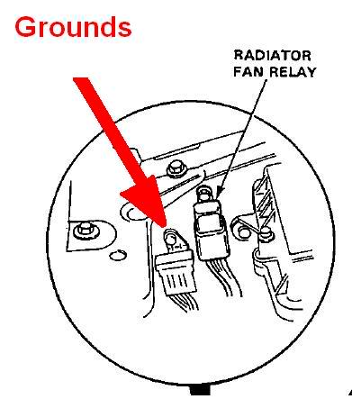
3. Grounds
4. Bumper Lense
5. Headlight wiring (cut for wiring to JDM headlights on my Car)
6. Corner Lights (or Corner and Side marker is JDM fenders installed)
7. Radiator Fan
8.Windshield Wiper Motor (not pictured)
* on the note of the WW Motor, it is NOT on the headlight harness (the one we're tucking right now) Its on the wiring from the shock tower near the fuse box.
Also plese note I'm not a wiring Guru, so this isn't done to the fullest like Ryan or EF8Kid would do, but it's good enough for me. And by this I mean the mounting of the Relay and Ground Box, I'm sure they relocated them somewhere else to make it a little cleaner.....but if you cant see it, ya cant see it, know what I mean?
So basically what we're doin here's simple:
-The ONLY thing that's gonna reach w/o being extended are the corner lights
-So we're extending every other wire.
-When extending each thing, I would recommend you cut off the plug, and plug it in, and then figure out how much wire you need to extend them properly.
-The WW Motor wiring goes right up into the fender (in the same spot as the rest of the wires) and right out to the plug, right there.
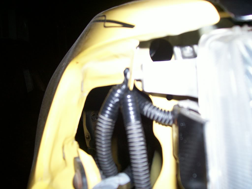
-I didn't feel like extending all the grounds for the Grounds Box and wires for the Fan Relay, so I just extended the few necessary and I'm mounting them under the fender, in the area pictured.
-Other than that, everything is going to the same place, it all goes in 1 loom up til when it comes out of the fender, then you'll have to seperate each thing's wiring.
-Once all the wire lengths have been figured out and cut, solder them onto the WIRING HARNESS first, and then loom them up long enough to go through and out the fender.
-Run them through the fender, and when the come out, solder each wire to it's plug and then loom em up and your good to go.
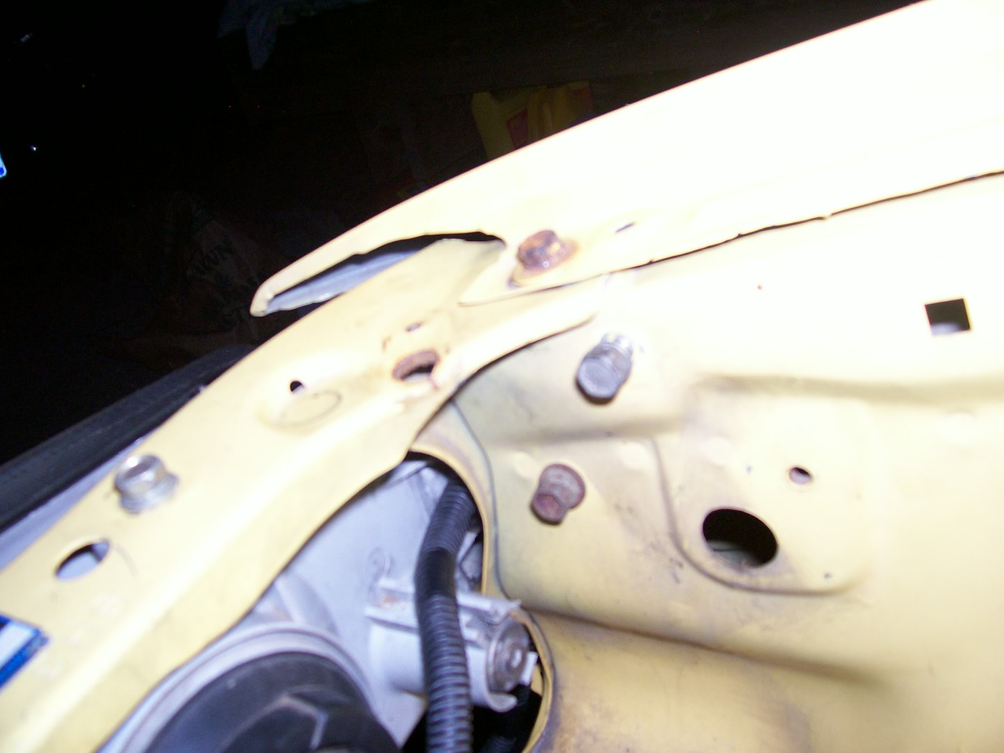
You can run them out the little hole you see in the pictures where the corner light goes, but I didnt, I pryed that a slight bit to fit the plugs through, then bent it back. I did this so my Wiring is easily removable (all plugs fit through the hole but the Fan plug, so I only have to cut it off if I wanna bring the wiring out, instead of all of them)
So that's about it for how to tuck the passengerside. go do that ****!
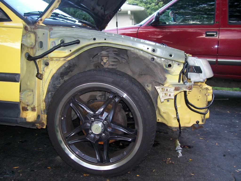
Pictures:
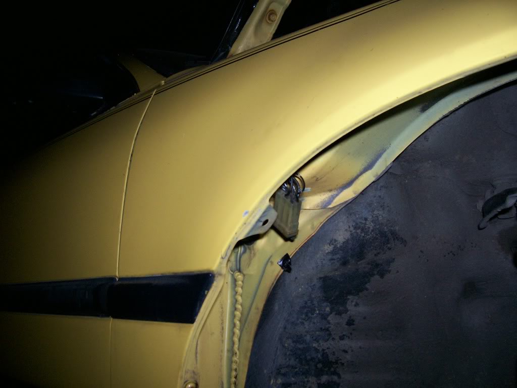
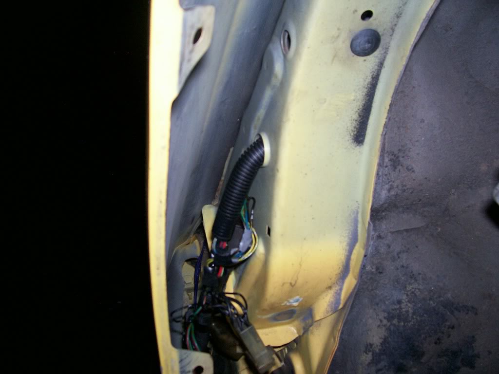
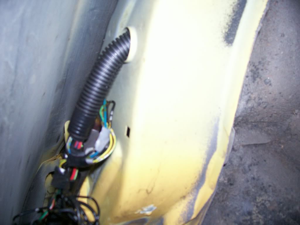
Where they come out:
Please note I have one of the corner light's wiring retained in the fender area to go to my JDM Sidemarker light, and that the WW Motor wiring is not pictured at all. Just want to make sure everythings clear.
EDIT: Here's the only other real progress post from the rest of the thread, if anybody needs anything more clearly explained for the D/S, let me know. Next time I do a tuck I'll take pics of the D/S process.
So here you go, this is the Passengerside after I relocated the Ground Box and Radiator Fan Relay to inside the cabin. I had them in the fenderwell but it was tacky and I was tracing wires, so I just redid it.
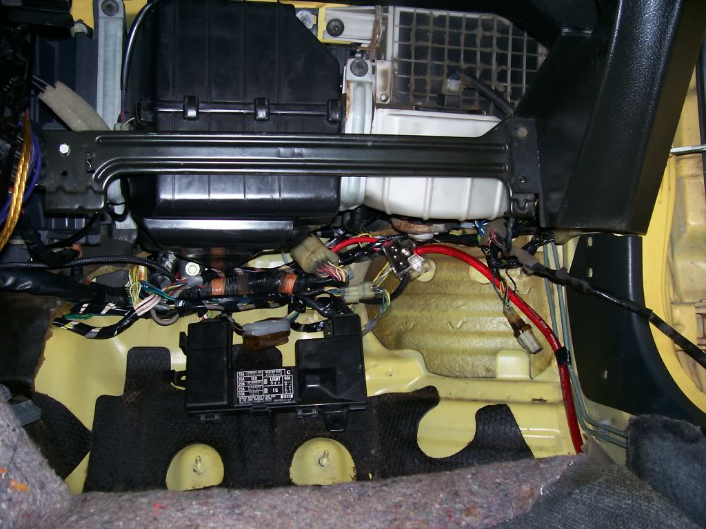
Here are pics of how I've arranged the wiring inside the cabin.
I've mounted the Ground box by the kick panel, and the relay is next to it.
The ECU is located behind the center console, so I can easily remove it nightly.
Now as I said before, I haven't shortened any of the wiring so it's not neat at all, but it fits. I don't have the time to shorten it all right now, or time to deal with possible problems that could arise if I do so, so it's not shortened.
But eveything fits nicely, if I could find my ECU cover it'd cover it all.
Tell me what you guys think:
.
Modified by G0crxG0 at 9:42 AM 12/6/2006
Modified by G0crxG0 at 9:43 AM 12/6/2006
SUPRISE!
This isn't another thread asking about them, but rather one explaining them a bit more!
Bet ya didn't expect that!
Now, the car: 1988 CRX SI
The Engine: B18C1 OBD1
-Things Specific to this project:
-Only running one 4wire o2.
-No Knock Sensor
-No IAB's (I have S2 IM)
-No Fan Switch plug included as I dont have one at the moment.
Now since I have a slightly custom setup for my wiring, there are going to be some things different between what I'm doing, and what you might want to do.
It's not that hard, so if there are additional wires you have, that I dont, that need included: just figure whether they need extended, then tuck them appropriately.
If I'm wiring things you don't have (Vtec stuff) just ignore it.
And as a general starting point for this, my instructions are going as if you have your front bumper, fenders, and ecu cover removed.
A tip also, never do this w/o the engine in the car. You need to test fit everything to make sure everything has proper length.
Another tip, if possible, do this w/o the radiator installed, the hoses REALLY get in the way....
ONE more tip...Don't completely wrap things until your 100% CERTAIN of them (I.E. your tuck is done except the final wrap) keep it wrapped once every 4 inches or so to keep wires together, but dont fully wrap in case you need to make alterations.
Ok, so first things first, easiest place to start:
<u>AC WIRING</u>
If your running AC, skip this.
If not, get rid of this wiring if you havent already. It's really simple to tell the AC wiring from Headlight and other wiring b/c it's all in one strand, and all enters the cockpit at one point, in the upper left of the firewall.
Here's the CRX Manual's Diagram of the AC Wiring:
Now here's one of the actual wiring, all removed:
Like I said, it all goes into one spot. Unless you specifically want to maintain the wires, cut them at the firewall, and unplug them under the dash (pictured below) and pull the remaining wire through the dash and its outta there!
Congrats, your free of AC wiring in the engine bay!
<u>PASSENGERSIDE TUCK </u>
So this sides got all the major ****. Fuse Box, big 14 Pin connector, etc. all the good stuff that makes your engine bay so cluttered you go to these lengths to free up some space!
-Start off by unplugging all your headlights if you havent, aswell as the Windshield Wiper Motor, Fuse Box connections, etc.
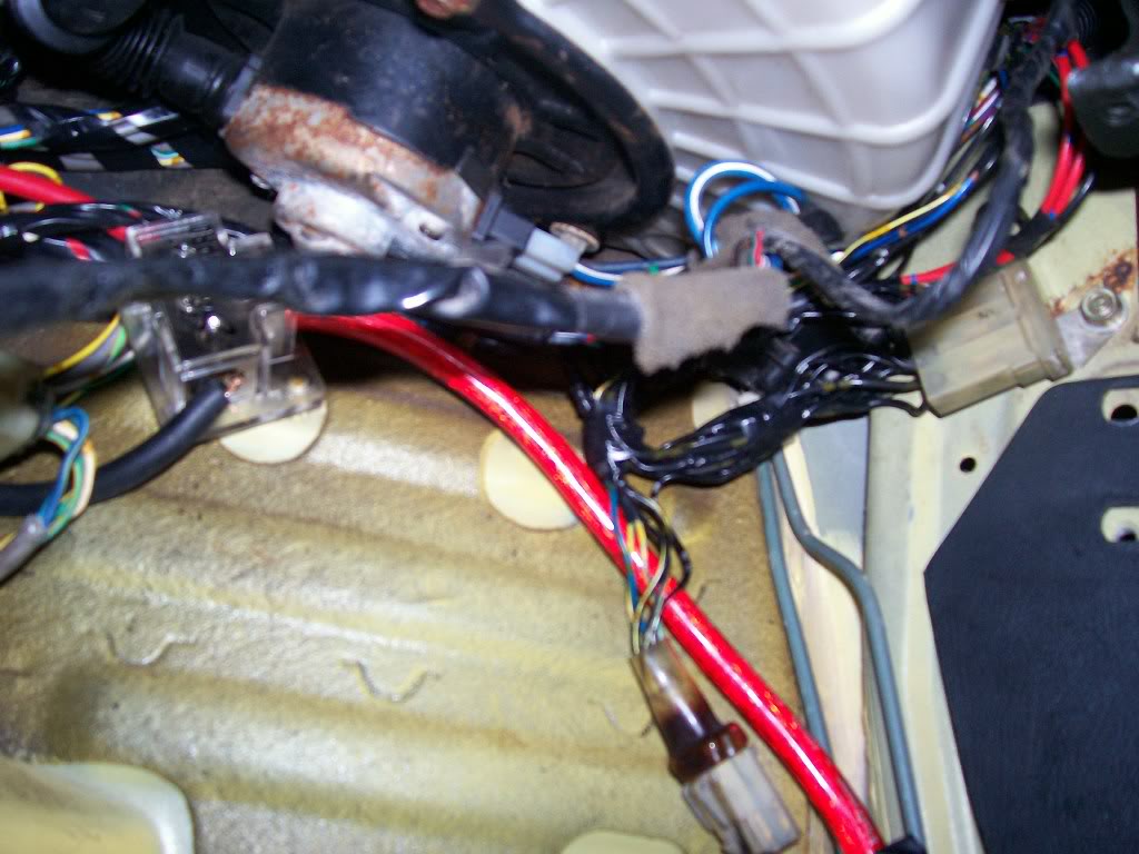
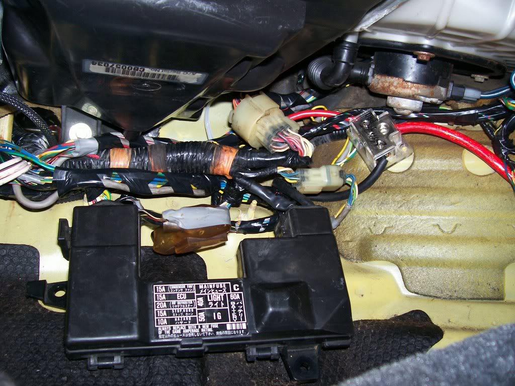
Here's a pic of the Fuse Box wiring undone:
And a pic of the wires from the Headlight Loom that cross into the fuse box/14 pin connector wiring. These will eventually have to be extended, or however you do it as a couple of them are just grounds:
-Now it's really simple: Just unplug everything on this side, and shove all the wiring and connectors into the cockpit.
When you do so, leave ALL the engine connections connected. The only one's you'll have to disconnect to move this wiring are: The Map Sensor and the plug next to it, the starter wire (black with white stripe) all the rest will/should reach.
-When you shove it all in, it comes in in 2 bundles:
Bunch 1.The wiring that <u>WENT</u> into the engine bay.
This wiring <u>USED</u> to go INTO the bay. Now it doesn't
Bunch 2.The wiring that GOES TO THE ENGINE, and connnects the above mentioned wiring (Bunch 1)
Here are pictures of what it looks like with Bunch 1 pulled into the Cockpit:
Now on Bunch 1, all the connectors/things brought into the Cockpit can stay there EXCEPT: The Map Sensor and the plug next to it. I dont know what the plug next to it does, but I dont need it as I dont use the Stock Map Sensor location, as my S2 Intake Manifold has one on it. So in my case, I only need to run the Map Sensor BACK into the Engine Bay, you may need to do the other plug aswell. To run the Map Sensor back in there, just split the loom and fish the 3 wires for it out of the sea of other wires, and run it back into the bay.
Now there's a Dust Boot that was on Bunch 1 that went into the Engine bay, that kept **** out of the **** pit. It was important to me to maintain this, so I could put it on Bunch 2, the bunch that is now going into the Engine bay, so to continue keeping **** out of the cockpit. So I just depinned the wires where needed and strategically fit it over the plugs and got it off. While doing this, I seperated each strand of wires from the giant Bunch. That way, when I go to shorten them up, it'll be easy to do it without getting confused. Here's a pic of them all seperated and bundled:
Once you've done this, all there is to do is run the Headlight wiring through the fender wall. That is pretty much self explanatory, you'll have to extend a few wires and depin some plugs but you'll get it. I haven't done it yet so I don't have pics, but I will tommorow. For now if you need to see what I'm talkin about, the places to route the wires through are pictured in the other Wire Tuck how to's.
<u>ENGINE WIRING</u>
Now for the fun part. This is probably the most complicated and tedious part of the tuck. So lets start out easy:
For reference purposes, this is a drawing of what your Engine wiring harness looks like FROM THE FACTORY:
<u>Fuel Injector Wiring </u> - The FI Wiring is seperate from the rest of the engine's wiring (which it is taped into). Now I'm OBD1, so now FI Resistor Box. But I didn't just solder the wires together, I repined the OBD1 Injector wires into their proper spots on the 6pin connector they should go into, that connects on the Driverside.
Either way, OBD0 or 1, your injector wiring is seperate, and I recomend seperating it.
Here's a pic of it seperated and loomed up. Notice the 6 pin connector on the end?
IMPORTANT: There is a BLUE wire in the 6 pin connector. This wire IS part of the engine wiring harness. De pin it, and it will eventually be ran through the engine harness and out by the Alternator, to meet the 6pin connector and plug in
this will be detailed momentarily.Now it's time for the majority of the wiring. This is again pretty self explanatory:
Based on where the wires are headed, un-loom them, bunch them together properly, and tape them as you go. Remember when doing this the idea is to have as little wire as possible showing, so try to keep things in the FEWEST number of looms as possible, aswell as angling the wire in the way you'd want it permanently hidden.
The only wire that'll need extended is the Starter Wire (Black with White Stripe) Pictured below (connecting to the starter on the right)
I kept it simple: 1 loom for the engine connections on the rear and IM, one loom for the TPS and MS, and one for the Coolant Temp, TW Sensor and Vtec plugs. I had a RyWire subharness but I just integrated it into the wiring: vtec plugs in one loom, and ran the o2 wiring in the Rear loom.
Here's a pic of the looms taped together that would eventually be the rear loom, in my test fit of how I'd run them as one. As you can see, I just got them situated properly and used little bands on tape to mark where they'd end up eventually.
Here's a pic of them wired together the way they'd end up:
And one of them finalized and loomed up:
I didn't take pics of the looming process of the other 2 looms of the Engine Wiring b/c their so simple and self explanatory, I mean their all RIGHT THERE, you just loom them and bundle the wires, simple as that.
So now you should have your wiring for the engine minimalized and tucked to a decent degree. If it's not perfect no biggie, you can always alter it in the future. When doing something like this for the first time, trial and error is key.
Here's a pic of how I wired everything engine related together, and a few shots of the FI Wiring and Engine Bay (please keep in mind this is mid tuck):
Sorry if the pictures suck or you think this whole thread does.....just thought the basic principles of what I did would be applicable to everyone, and I wanted to try and contribute to our community!
Will have the 2nd half of the write up on here shortly!
EDIT: I wanna take a second to thank EF8KID, along with Magick211 and any others who have made wire tuck how to's in the past. Obviously this wouldn't be goin down without their contributions. Also, a major TY to CRXBart, for had he not taught me how to depin, I'd be knee deep in solder
Modified by G0crxG0 at 10:42 PM 7/6/2006
Second post
<u>Passengerside Wiring through Fenders:</u>
So you've got your wiring in the cockpit and your ready to run the wiring throught the Fenders. Excellent, Great, Grand, Wonderful!
So here's what we're running through there, by number and pictured below (NOTE* - The Windshield wiper needs ran through here too, but is not pictured do to my ******* up!)
1. Radiator Fan Relay
2. Horn Buttons
3. Grounds
4. Bumper Lense
5. Headlight wiring (cut for wiring to JDM headlights on my Car)
6. Corner Lights (or Corner and Side marker is JDM fenders installed)
7. Radiator Fan
8.Windshield Wiper Motor (not pictured)
* on the note of the WW Motor, it is NOT on the headlight harness (the one we're tucking right now) Its on the wiring from the shock tower near the fuse box.
Also plese note I'm not a wiring Guru, so this isn't done to the fullest like Ryan or EF8Kid would do, but it's good enough for me. And by this I mean the mounting of the Relay and Ground Box, I'm sure they relocated them somewhere else to make it a little cleaner.....but if you cant see it, ya cant see it, know what I mean?
So basically what we're doin here's simple:
-The ONLY thing that's gonna reach w/o being extended are the corner lights
-So we're extending every other wire.
-When extending each thing, I would recommend you cut off the plug, and plug it in, and then figure out how much wire you need to extend them properly.
-The WW Motor wiring goes right up into the fender (in the same spot as the rest of the wires) and right out to the plug, right there.
-I didn't feel like extending all the grounds for the Grounds Box and wires for the Fan Relay, so I just extended the few necessary and I'm mounting them under the fender, in the area pictured.
-Other than that, everything is going to the same place, it all goes in 1 loom up til when it comes out of the fender, then you'll have to seperate each thing's wiring.
-Once all the wire lengths have been figured out and cut, solder them onto the WIRING HARNESS first, and then loom them up long enough to go through and out the fender.
-Run them through the fender, and when the come out, solder each wire to it's plug and then loom em up and your good to go.
You can run them out the little hole you see in the pictures where the corner light goes, but I didnt, I pryed that a slight bit to fit the plugs through, then bent it back. I did this so my Wiring is easily removable (all plugs fit through the hole but the Fan plug, so I only have to cut it off if I wanna bring the wiring out, instead of all of them)
So that's about it for how to tuck the passengerside. go do that ****!
Pictures:
Where they come out:
Please note I have one of the corner light's wiring retained in the fender area to go to my JDM Sidemarker light, and that the WW Motor wiring is not pictured at all. Just want to make sure everythings clear.
EDIT: Here's the only other real progress post from the rest of the thread, if anybody needs anything more clearly explained for the D/S, let me know. Next time I do a tuck I'll take pics of the D/S process.
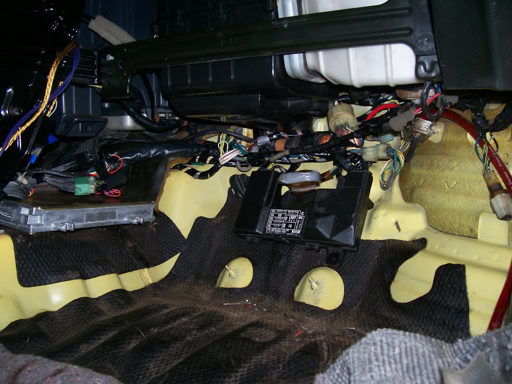
So here you go, this is the Passengerside after I relocated the Ground Box and Radiator Fan Relay to inside the cabin. I had them in the fenderwell but it was tacky and I was tracing wires, so I just redid it.
Here are pics of how I've arranged the wiring inside the cabin.
I've mounted the Ground box by the kick panel, and the relay is next to it.
The ECU is located behind the center console, so I can easily remove it nightly.
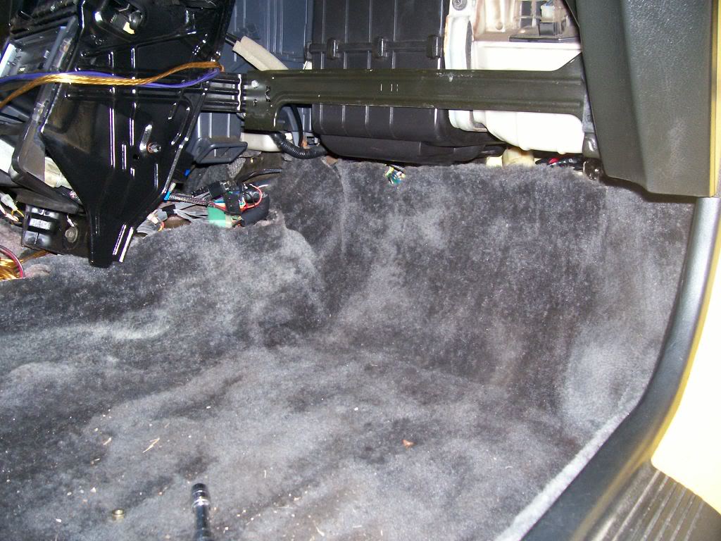
Now as I said before, I haven't shortened any of the wiring so it's not neat at all, but it fits. I don't have the time to shorten it all right now, or time to deal with possible problems that could arise if I do so, so it's not shortened.
But eveything fits nicely, if I could find my ECU cover it'd cover it all.
Tell me what you guys think:
.
Modified by G0crxG0 at 9:42 AM 12/6/2006
Modified by G0crxG0 at 9:43 AM 12/6/2006
Honda-Tech Member
Joined: Apr 2006
Posts: 5,160
Likes: 0
From: Palmdale, CA
damn homie your write ups are great. at this rate you should start your own ef mod manual and sell that ****. anyway i guess the whole wire tuck thing turned me off in doing it but after reading your very informative write up its given me hope in doing it thanks.
Thread Starter
Honda-Tech Member
Joined: Apr 2006
Posts: 1,683
Likes: 2
From: Columbus, OH
<TABLE WIDTH="90%" CELLSPACING=0 CELLPADDING=0 ALIGN=CENTER><TR><TD>Quote, originally posted by 661rex89si »</TD></TR><TR><TD CLASS="quote"> the whole wire tuck thing turned me off in doing it but after reading your very informative write up its given me hope in doing it thanks.</TD></TR></TABLE>
Thank you, that is why I do these things.
I should make a EF mod manual, haha, could get paid.....
Thank you, that is why I do these things.
I should make a EF mod manual, haha, could get paid.....
 good info
 Trending Topics

Member
Joined: Jun 2005
Posts: 2,846
Likes: 0
From: Mount Holly, NJ, USA
Thread Starter
Honda-Tech Member
Joined: Apr 2006
Posts: 1,683
Likes: 2
From: Columbus, OH
<TABLE WIDTH="90%" CELLSPACING=0 CELLPADDING=0 ALIGN=CENTER><TR><TD>Quote, originally posted by SVOboy »</TD></TR><TR><TD CLASS="quote">Bump, just finished my writing: http://crxmpg.com/wiretuck.html
You're an inspiration!</TD></TR></TABLE>
Damn, let's hear it for SVOboy, that is a very, very nice write up you've done!!!
You're an inspiration!</TD></TR></TABLE>
Damn, let's hear it for SVOboy, that is a very, very nice write up you've done!!!
Thread Starter
Honda-Tech Member
Joined: Apr 2006
Posts: 1,683
Likes: 2
From: Columbus, OH
<TABLE WIDTH="90%" CELLSPACING=0 CELLPADDING=0 ALIGN=CENTER><TR><TD>Quote, originally posted by SVOboy »</TD></TR><TR><TD CLASS="quote">
(I want a glasstop, *cry*)</TD></TR></TABLE>
Thiers one on eBay right now for $600 (killer price)
<TABLE WIDTH="90%" CELLSPACING=0 CELLPADDING=0 ALIGN=CENTER><TR><TD>Quote, originally posted by Pee Wee »</TD></TR><TR><TD CLASS="quote">nice writeup.
now ditch that charcoal canister </TD></TR></TABLE>
It's already on it's way out, where you been man? I havent seen you around here much lately
Thread Starter
Honda-Tech Member
Joined: Apr 2006
Posts: 1,683
Likes: 2
From: Columbus, OH
<TABLE WIDTH="90%" CELLSPACING=0 CELLPADDING=0 ALIGN=CENTER><TR><TD>Quote, originally posted by Pee Wee »</TD></TR><TR><TD CLASS="quote">school 
 now only if i knew how to depin</TD></TR></TABLE>
haha easiest thing ever, most helpful too!
Think of 2 L's stacked on each other like a square.
one of them is the pin, the other is part of the plug.
from the pin side, lift on it and pull. once it's up over the plug thing, it'll slide right out.
now only if i knew how to depin</TD></TR></TABLE>haha easiest thing ever, most helpful too!
Think of 2 L's stacked on each other like a square.
one of them is the pin, the other is part of the plug.
from the pin side, lift on it and pull. once it's up over the plug thing, it'll slide right out.
Honda-Tech Member
Joined: Jan 2006
Posts: 1,119
Likes: 0
From: Tallahassee, Fl
Great write up.
Do you have any pictures of where the fuse box goes and stuff?
I'd like to see how you mounted it and it's location, etc.
Thx. IM me or Email if you want. apmcrx@hotmail.com
-Andrew
Do you have any pictures of where the fuse box goes and stuff?
I'd like to see how you mounted it and it's location, etc.
Thx. IM me or Email if you want. apmcrx@hotmail.com
-Andrew
Thread Starter
Honda-Tech Member
Joined: Apr 2006
Posts: 1,683
Likes: 2
From: Columbus, OH
<TABLE WIDTH="90%" CELLSPACING=0 CELLPADDING=0 ALIGN=CENTER><TR><TD>Quote, originally posted by Andrew Marquis »</TD></TR><TR><TD CLASS="quote">Great write up.
Do you have any pictures of where the fuse box goes and stuff?
I'd like to see how you mounted it and it's location, etc.
Thx. IM me or Email if you want. apmcrx@hotmail.com
-Andrew</TD></TR></TABLE>
Thanks for the comment,
I can't provide that picture b/c I haven't done it yet. Nothing is mounted inside the car yet.
It's gonna be a tuff fit b/c I'm keeping all my blower stuff for defog and heat purposes. There are pics around of where people have mounted them but most of them have removed their ****.
When I do do that though, I'll post pics in here