

Bearing Clearance Measurement

Thread Starter
Honda-Tech Member
Joined: Jan 2003
Posts: 10,170
Likes: 3
From: So Cal
I see alot of posts on this forum regarding confusion about bearing clearances, how to measure them , whether or not to use plasti-gauge, and whether or not ACL is a good or bad choice to go with. I was doing a little work today and decided to take some pics and write this up to maybe help some people out.
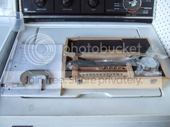
This is what youll need. A properly sized micrometer, in this case 2-3"; a notepad to keep track of your findings, and a dial bore gauge. (You can alternatively use telescoping snap gauges or an inside mic if you dont have a dial bore gauge, but i feel this is a bit more accurate.) You will also note the standard next to the mic, this is used to calibrate the micrometer.
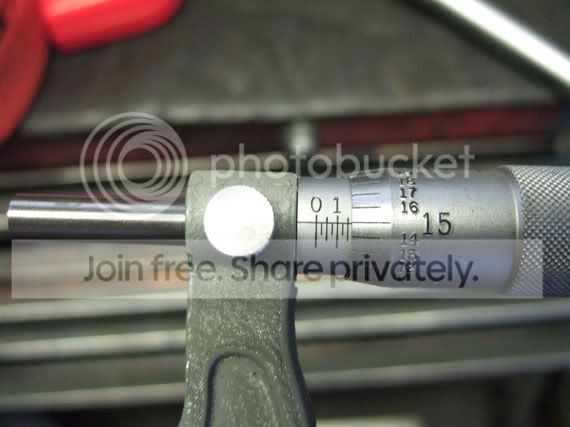
Here you can see i set the mic to 2.1650", which is right around where the main bearing house bore will be, give or take a few 10 thou. The purpose of this is to set the gauge as close as possible to the final reading without bottoming out the needle.

Here i have placed the gauge in a vice using rubber protectors, and compressed the needle to 2.1650". This is very tricky and should not be done without a vice. Next you zero out the indicator as it sits on 2.1650

With that done, i placed the a green OEM honda bearing in the main bearing cap and saddle. OEM Green are right in the middle of the thickness, and if you have a thickness chart, you can take the readings you get from this excercise and add or subtract clearance as necessary to end up where you want. If you dont have any bearings handy, you can measure the bearing bore without the bearings, then use a thickness chart from there to figure what the clearance would be.
Here im lubing up the thread of the main cap bolts with the same lubricant that will be used during the final assembly, 10w-30 oil. Be sure to follow the factory 2 step torque procedure for the cap.

Once you have the cap tightened down, rock the gauge back and forth until you find the tightest spot on the gauge, making sure you are 90 deg. from the crank centerline. If you are off, obviously the needle will have to travel farther and youre reading will be that you have more clearance than you actually do. Since i set the gauge for 2.1650" , i managed to get a reading of 0 on the dial bore gauge, meaning the bearing bore was exactly 2.1650". If it had moved a tick to the left, i would have been at 2.1645 (the gauge reads in .0005 increments), and if it moved to the right, would have been 2.1655.
Next you would mic the crank (which i havent done yet) but for example we'll say its
2.1635". That would mean i have .0015" clearance. If i wanted more, i would substitue a thinner bearing, less i would sub. a thicker bearing.
I personally like to set clearances on a motor this way and use plastigauge to verify results. Some people swear by plastigauge all the way. Im not saying theyre wrong, and im not saying im right, im saying theres more than one way to skin a cat.
Where ACL's can hurt you is their lack of adjustability. If you have a machined crank, and one journal needs a bit more clearance, then you might not be able to achieve this with the ACL's. If everything checks out good with the ACL's clearance, wise, they are an excellent bearing for the money, and there is no reason not to use them. Hope this helps.

This is what youll need. A properly sized micrometer, in this case 2-3"; a notepad to keep track of your findings, and a dial bore gauge. (You can alternatively use telescoping snap gauges or an inside mic if you dont have a dial bore gauge, but i feel this is a bit more accurate.) You will also note the standard next to the mic, this is used to calibrate the micrometer.
Here you can see i set the mic to 2.1650", which is right around where the main bearing house bore will be, give or take a few 10 thou. The purpose of this is to set the gauge as close as possible to the final reading without bottoming out the needle.
Here i have placed the gauge in a vice using rubber protectors, and compressed the needle to 2.1650". This is very tricky and should not be done without a vice. Next you zero out the indicator as it sits on 2.1650
With that done, i placed the a green OEM honda bearing in the main bearing cap and saddle. OEM Green are right in the middle of the thickness, and if you have a thickness chart, you can take the readings you get from this excercise and add or subtract clearance as necessary to end up where you want. If you dont have any bearings handy, you can measure the bearing bore without the bearings, then use a thickness chart from there to figure what the clearance would be.
Here im lubing up the thread of the main cap bolts with the same lubricant that will be used during the final assembly, 10w-30 oil. Be sure to follow the factory 2 step torque procedure for the cap.
Once you have the cap tightened down, rock the gauge back and forth until you find the tightest spot on the gauge, making sure you are 90 deg. from the crank centerline. If you are off, obviously the needle will have to travel farther and youre reading will be that you have more clearance than you actually do. Since i set the gauge for 2.1650" , i managed to get a reading of 0 on the dial bore gauge, meaning the bearing bore was exactly 2.1650". If it had moved a tick to the left, i would have been at 2.1645 (the gauge reads in .0005 increments), and if it moved to the right, would have been 2.1655.
Next you would mic the crank (which i havent done yet) but for example we'll say its
2.1635". That would mean i have .0015" clearance. If i wanted more, i would substitue a thinner bearing, less i would sub. a thicker bearing.
I personally like to set clearances on a motor this way and use plastigauge to verify results. Some people swear by plastigauge all the way. Im not saying theyre wrong, and im not saying im right, im saying theres more than one way to skin a cat.
Where ACL's can hurt you is their lack of adjustability. If you have a machined crank, and one journal needs a bit more clearance, then you might not be able to achieve this with the ACL's. If everything checks out good with the ACL's clearance, wise, they are an excellent bearing for the money, and there is no reason not to use them. Hope this helps.
Junior Member
Joined: Jan 2005
Posts: 89
Likes: 0
From: The ATL, GA, US
<TABLE WIDTH="90%" CELLSPACING=0 CELLPADDING=0 ALIGN=CENTER><TR><TD>Quote, originally posted by Combustion Contraption »</TD></TR><TR><TD CLASS="quote">
Where ACL's can hurt you is their lack of adjustability. If you have a machined crank, and one journal needs a bit more clearance, then you might not be able to achieve this with the ACL's. If everything checks out good with the ACL's clearance, wise, they are an excellent bearing for the money, and there is no reason not to use them. Hope this helps.
</TD></TR></TABLE>
Your exactly right my friend. ACL bearing may and may not be for you. You have to check those clearances to see what will work for you. I had to learn it the hard way.
Where ACL's can hurt you is their lack of adjustability. If you have a machined crank, and one journal needs a bit more clearance, then you might not be able to achieve this with the ACL's. If everything checks out good with the ACL's clearance, wise, they are an excellent bearing for the money, and there is no reason not to use them. Hope this helps.
</TD></TR></TABLE>Your exactly right my friend. ACL bearing may and may not be for you. You have to check those clearances to see what will work for you. I had to learn it the hard way.


Junior Member
Joined: Jan 2003
Posts: 912
Likes: 0
From: buffalo, new york, united states
wow, you dont see many good posts like this one. I think one of the biggest problem when it comes to using micrometers and such is that people dont know how to read/understand them. Maybe you can shed some light on that as well.
:tup: to a great post.
:tup: to a great post.
Trending Topics
Thread Starter
Honda-Tech Member
Joined: Jan 2003
Posts: 10,170
Likes: 3
From: So Cal
<TABLE WIDTH="90%" CELLSPACING=0 CELLPADDING=0 ALIGN=CENTER><TR><TD>Quote, originally posted by DonF »</TD></TR><TR><TD CLASS="quote">Is that your "wet-flow" flow bench the tools are laying on?  </TD></TR></TABLE>
the secret is out!
</TD></TR></TABLE>the secret is out!

Thread Starter
Honda-Tech Member
Joined: Jan 2003
Posts: 10,170
Likes: 3
From: So Cal
<TABLE WIDTH="90%" CELLSPACING=0 CELLPADDING=0 ALIGN=CENTER><TR><TD>Quote, originally posted by ITR#132 »</TD></TR><TR><TD CLASS="quote"> It would be great to also include the bearing color thickness measurements with this thread.</TD></TR></TABLE>
*applicable to B and K*
Main Bearing thickness by color
Blue 2.013-2.010 mm 0.0793�- 0.0791�
Black 2.010-2.007 mm 0.0791�- 0.0790�
Brown 2.007-2.004 mm 0.0790�- 0.0789�
Green 2.004-2.001 mm 0.0789�- 0.0788�
Yellow 2.001-1.998 mm 0.0788�- 0.0787�
Pink 1.998-1.995 mm 0.0787�- 0.0785�
Red 1.995-1.992 mm 0.0785�- 0.0783�
Rod bearing thickness by color
Blue 1.510-1.507 mm 0.0594�- 0.0593�
Black 1.507-1.504 mm 0.0593�- 0.0592�
Brown 1.504-1.501 mm 0.0592�- 0.0591�
Green 1.501-1.498 mm 0.0591�- 0.0590�
Yellow 1.498-1.495 mm 0.0590�- 0.0589�
Pink 1.495-1.492 mm 0.0589�- 0.0587�
Red 1.492-1.489 mm 0.0587�- 0.0586�
It would be great to also include the bearing color thickness measurements with this thread.</TD></TR></TABLE>*applicable to B and K*
Main Bearing thickness by color
Blue 2.013-2.010 mm 0.0793�- 0.0791�
Black 2.010-2.007 mm 0.0791�- 0.0790�
Brown 2.007-2.004 mm 0.0790�- 0.0789�
Green 2.004-2.001 mm 0.0789�- 0.0788�
Yellow 2.001-1.998 mm 0.0788�- 0.0787�
Pink 1.998-1.995 mm 0.0787�- 0.0785�
Red 1.995-1.992 mm 0.0785�- 0.0783�
Rod bearing thickness by color
Blue 1.510-1.507 mm 0.0594�- 0.0593�
Black 1.507-1.504 mm 0.0593�- 0.0592�
Brown 1.504-1.501 mm 0.0592�- 0.0591�
Green 1.501-1.498 mm 0.0591�- 0.0590�
Yellow 1.498-1.495 mm 0.0590�- 0.0589�
Pink 1.495-1.492 mm 0.0589�- 0.0587�
Red 1.492-1.489 mm 0.0587�- 0.0586�
Honda-Tech Member
Joined: Mar 2001
Posts: 4,295
Likes: 0
From: North East
I do it slightly fifferent.
I mic the crank
Then set by bore gauge as you described witth a micrometer with the bore gauge in a vise/holder and set the dial to 0.
So now your bore gauge is set to the exact crank thickness at 0
Then stick it in the tq'd cap with bearing and read the gauge , the difference it moved away from 0 is your clearance.
Thread Starter
Honda-Tech Member
Joined: Jan 2003
Posts: 10,170
Likes: 3
From: So Cal
<TABLE WIDTH="90%" CELLSPACING=0 CELLPADDING=0 ALIGN=CENTER><TR><TD>Quote, originally posted by Tbone »</TD></TR><TR><TD CLASS="quote">I do it slightly fifferent.
I mic the crank
Then set by bore gauge as you described witth a micrometer with the bore gauge in a vise/holder and set the dial to 0.
So now your bore gauge is set to the exact crank thickness at 0
Then stick it in the tq'd cap with bearing and read the gauge , the difference it moved away from 0 is your clearance.</TD></TR></TABLE>
DOH!
I was taught that way when i first learned, and this is the method you should use if you have the crank handy, during the process of this write up i did not...

Member
Joined: May 2002
Posts: 5,197
Likes: 1
From: Atl. Beach, fl, duval
The problem with using a dial bore guage with bearings in the rod is that you usally leave marks or scratches on the soft bearing. We mic the crank, dial bore the rod (torqued) check bearing thickness (x 2) add and subtract.
Thread Starter
Honda-Tech Member
Joined: Jan 2003
Posts: 10,170
Likes: 3
From: So Cal
<TABLE WIDTH="90%" CELLSPACING=0 CELLPADDING=0 ALIGN=CENTER><TR><TD>Quote, originally posted by DonF »</TD></TR><TR><TD CLASS="quote">The problem with using a dial bore guage with bearings in the rod is that you usally leave marks or scratches on the soft bearing. We mic the crank, dial bore the rod (torqued) check bearing thickness (x 2) add and subtract.</TD></TR></TABLE>
Yeah, i keep a set of OEM bearings that i use just for measurement. For this reason exactly, they scratch. The K ones (coated) scratch VERY easily.
Yeah, i keep a set of OEM bearings that i use just for measurement. For this reason exactly, they scratch. The K ones (coated) scratch VERY easily.

Honda-Tech Member

Joined: Sep 2003
Posts: 5,072
Likes: 2
From: Raleigh, NC
i do it a little different.. kinda like how tbone does it. i measure the crank w/the mic, set it in the stand, then zero the bore guage on block/rod. this way it dosnt matter if my mic is out of calibration, im just using it for a baseline to compare things.
i have done it how don says when i dont have bearings.
i have done it how don says when i dont have bearings.
Joined: Mar 2004
Posts: 2,568
Likes: 0
From: Titusville, FL, US
What would be nice is if you determined your clearance using your measuring tools, then use plastigauge and see how close to those measurements it comes. It would suck if people are relying on plasigauge, and it not be reliable at all. Has anyone tried both methods and not like the accuracy of the plastigauge?