

The official auto to manual ECU conversion thread

Thread Starter
Joined: Nov 2002
Posts: 192
Likes: 1
From: va, usa
First I want to thank Jim Truett for his write-up on this conversion which help me a lot and also I want to thank the members of Honda-tech (Prelude forum) for always keeping it real. This write up is more so you know what is involved and what you are getting yourself into. 
Auto to manual ECU conversion;
1. Disconnect the battery Pos terminal first and then neg.

2. Locate the Ecu, Passenger side underneath the rug.

3. The Ecu is on the inside of a protective cover, which have 4 10mm nuts holding it in place; you will need a 10mm deep socket to free the Ecu.

4. Remove the harness.
5. Unbolt the Ecu from its protective cover.
6. Remove the lit from both side of the Ecu.

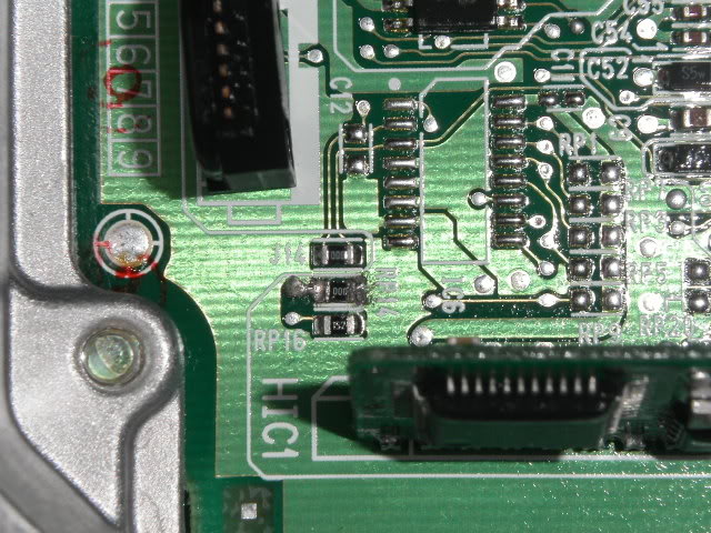
7. Locate the 000 resistor that is label RP13.

8. In addition, locate the target area RP14 on the other side of the circuit board.

9. Very carefully de-solder the resistor use a precision 1.0 mm flat screwdriver to carefully pry the resistor from the board (careful do not break the resistor) remember time is your friend do not rush take your time.

10. After successfully removing the 000 resistor from RP13 go ahead and place it on the position RP14
 .
.
11. Solder both end of the resistor.
12. Screw every thing back into place in the reverse order of removal.
13. Plug the Ecu and then plug the battery.

14. Turn the car on and the cell will be gone.


As you can see the cell was gone and the OBD2 scaner did not pick anything at all.
once again thank Jim Truett.
Auto to manual ECU conversion;
1. Disconnect the battery Pos terminal first and then neg.
2. Locate the Ecu, Passenger side underneath the rug.
3. The Ecu is on the inside of a protective cover, which have 4 10mm nuts holding it in place; you will need a 10mm deep socket to free the Ecu.
4. Remove the harness.
5. Unbolt the Ecu from its protective cover.
6. Remove the lit from both side of the Ecu.
7. Locate the 000 resistor that is label RP13.
8. In addition, locate the target area RP14 on the other side of the circuit board.
9. Very carefully de-solder the resistor use a precision 1.0 mm flat screwdriver to carefully pry the resistor from the board (careful do not break the resistor) remember time is your friend do not rush take your time.
10. After successfully removing the 000 resistor from RP13 go ahead and place it on the position RP14
.11. Solder both end of the resistor.
12. Screw every thing back into place in the reverse order of removal.
13. Plug the Ecu and then plug the battery.
14. Turn the car on and the cell will be gone.
As you can see the cell was gone and the OBD2 scaner did not pick anything at all.
once again thank Jim Truett.
Joined: Dec 2004
Posts: 237
Likes: 0
From: tampa, fl, us
not to sound like a moron but just to make sure I am understanding this.... I can take my JDM auto ecu and convert it to 5 spd with this method correct?
I have been asking this question here local, but know seemed to know the answer....
I have been asking this question here local, but know seemed to know the answer....

Junior Member
Joined: Dec 2004
Posts: 732
Likes: 0
From: Peach, usa
<TABLE WIDTH="90%" CELLSPACING=0 CELLPADDING=0 ALIGN=CENTER><TR><TD>Quote, originally posted by Digga4 »</TD></TR><TR><TD CLASS="quote">not to sound like a moron but just to make sure I am understanding this.... I can take my JDM auto ecu and convert it to 5 spd with this method correct?
I have been asking this question here local, but know seemed to know the answer.... </TD></TR></TABLE>
The method above is for 5g ECU. P5M
I have been asking this question here local, but know seemed to know the answer....
</TD></TR></TABLE>The method above is for 5g ECU. P5M
Thread Starter
Joined: Nov 2002
Posts: 192
Likes: 1
From: va, usa
<TABLE WIDTH="90%" CELLSPACING=0 CELLPADDING=0 ALIGN=CENTER><TR><TD>Quote, originally posted by xbn83 »</TD></TR><TR><TD CLASS="quote">
The method above is for 5g ECU. P5M</TD></TR></TABLE>
sorry, I forgot to mention that.
The method above is for 5g ECU. P5M</TD></TR></TABLE>
sorry, I forgot to mention that.
Trending Topics
Joined: Jul 2002
Posts: 2,374
Likes: 1
From: East Bay, CA, USA
<TABLE WIDTH="90%" CELLSPACING=0 CELLPADDING=0 ALIGN=CENTER><TR><TD>Quote, originally posted by khalal538 »</TD></TR><TR><TD CLASS="quote">How do you de-solder the chip?</TD></TR></TABLE>
I would do it with a fine tip on the soldering iron, some solder wick, and a pair of tweezers to grab the chip.
I would do it with a fine tip on the soldering iron, some solder wick, and a pair of tweezers to grab the chip.
Honda-Tech Member
iTrader: (1)
Joined: Oct 2004
Posts: 888
Likes: 1
From: Tucson...Cactus Town, Az, usa
i thought when you solder something it connects the chip to the board...how do you undo? Do you just heat up the part connected and pull the chip out when it comes loose?
Honda-Tech Member
Joined: Feb 2005
Posts: 1,180
Likes: 1
From: Fontana, CA
<TABLE WIDTH="90%" CELLSPACING=0 CELLPADDING=0 ALIGN=CENTER><TR><TD>Quote, originally posted by khalal538 »</TD></TR><TR><TD CLASS="quote">i thought when you solder something it connects the chip to the board...how do you undo? Do you just heat up the part connected and pull the chip out when it comes loose?</TD></TR></TABLE>
its just melted in. you can undo it, but just be careful to not undo anything else. if you dotn knwo how to do it then you should take it to someone that does.
its just melted in. you can undo it, but just be careful to not undo anything else. if you dotn knwo how to do it then you should take it to someone that does.
Thread Starter
Joined: Nov 2002
Posts: 192
Likes: 1
From: va, usa
<TABLE WIDTH="90%" CELLSPACING=0 CELLPADDING=0 ALIGN=CENTER><TR><TD>Quote, originally posted by khalal538 »</TD></TR><TR><TD CLASS="quote">i thought when you solder something it connects the chip to the board...how do you undo? Do you just heat up the part connected and pull the chip out when it comes loose?</TD></TR></TABLE>
yes when you solder, it connect whatever component to the circuit board in this case a resistor. you cannot just heat it up and hope it melt, you got to use a very fine de-soldering tool that will suck the solder that is been melted very fast and careful out of the way.
<TABLE WIDTH="90%" CELLSPACING=0 CELLPADDING=0 ALIGN=CENTER><TR><TD>Quote, originally posted by sharkcohen »</TD></TR><TR><TD CLASS="quote">
I would do it with a pair of tweezers to grab the chip.</TD></TR></TABLE>
I wouldn't recommend using tweezers in this case because you take the risk of grabbing it to hard to the point that the resistor will crack or snap in 2, remember this is a surface mount board what's holding the resistor on the board is the solder and in some cases some special non-conductive glue under the component. what I use a de-solder tool that you can get at radio shack and a small precision screwdriver to pry the resistor from the sides slowly also using magnifying glasses.
Thread Starter
Joined: Nov 2002
Posts: 192
Likes: 1
From: va, usa
<TABLE WIDTH="90%" CELLSPACING=0 CELLPADDING=0 ALIGN=CENTER><TR><TD>Quote, originally posted by SoOHiGH »</TD></TR><TR><TD CLASS="quote">This should be FAQ and by any chance do you know how to do this on a 4th gen p13 ecu?</TD></TR></TABLE>
I got no idea on how to do it on a p13, you should ask Jim Truett.
I got no idea on how to do it on a p13, you should ask Jim Truett.
Honda-Tech Member
iTrader: (1)
Joined: Oct 2004
Posts: 888
Likes: 1
From: Tucson...Cactus Town, Az, usa
ehhee...still doing the swap dunno until i put the tranny in...(installing clutch right now)...ill update you. 
Honda-Tech Member
iTrader: (1)
Joined: Oct 2004
Posts: 888
Likes: 1
From: Tucson...Cactus Town, Az, usa
hey, something a little off topic...where did you run your clutch line through? I'm looking all over and that metal line is a b*tch...i was thinking of running a rubber hose instead. 
Junior Member
Joined: Oct 2004
Posts: 161
Likes: 0
From: Richmond, BC, Canada
A performance shop is ding the swap for me.........so i am not sure how they are running it. They started today and will be done tomorrow!

If you guy want to do this to a 4th Gen P13 then all you have to do is remove <U>r11</U>.

btw i found this info on the pgmfi forum and im not responsible for anything that goes wrong while you do it to your car. have fun.
btw i just did it on a automatic p28 as well and its working great. (had to remove rp17 and rp18 then jump rp18)
btw i found this info on the pgmfi forum and im not responsible for anything that goes wrong while you do it to your car. have fun.
btw i just did it on a automatic p28 as well and its working great. (had to remove rp17 and rp18 then jump rp18)

B*a*n*n*e*d
Joined: Sep 2006
Posts: 144
Likes: 0
Image is not working anymore...
I've got a P13 for my H22 4Gen...so want to do the conversion to. Can't find R11 on the ECU. Only RP11, but that's not the one, right?
So only removing R11? Not like the 5 gen => Placing the resistor elsewere?
Anyone got a pic also?
Thx
I've got a P13 for my H22 4Gen...so want to do the conversion to. Can't find R11 on the ECU. Only RP11, but that's not the one, right?
So only removing R11? Not like the 5 gen => Placing the resistor elsewere?
Anyone got a pic also?
Thx


B*a*n*n*e*d
Joined: Sep 2006
Posts: 144
Likes: 0
<TABLE WIDTH="90%" CELLSPACING=0 CELLPADDING=0 ALIGN=CENTER><TR><TD>Quote, originally posted by Black-Engine »</TD></TR><TR><TD CLASS="quote">Image is not working anymore...
I've got a P13 for my H22 4Gen...so want to do the conversion to. Can't find R11 on the ECU. Only RP11, but that's not the one, right?
So only removing R11? Not like the 5 gen => Placing the resistor elsewere?
Anyone got a pic also?
Thx </TD></TR></TABLE>
Anyone please? Want to take a start with it...
I've got a P13 for my H22 4Gen...so want to do the conversion to. Can't find R11 on the ECU. Only RP11, but that's not the one, right?
So only removing R11? Not like the 5 gen => Placing the resistor elsewere?
Anyone got a pic also?
Thx
</TD></TR></TABLE>Anyone please? Want to take a start with it...