


Intercooler end tank design


Honda-Tech Member
Joined: Apr 2009
Posts: 71
Likes: 0
From: Tempe, AZ
 Re: Intercooler end tank design
I think one of things to remember when we say that most intercooler end tank designs are horrible, very few customers are willing to pay for 12 hours of labor making hammer formed end tanks. For most customers, sharp corners and flat sheet will be enough to keep everyone happy.
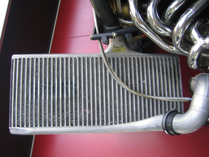
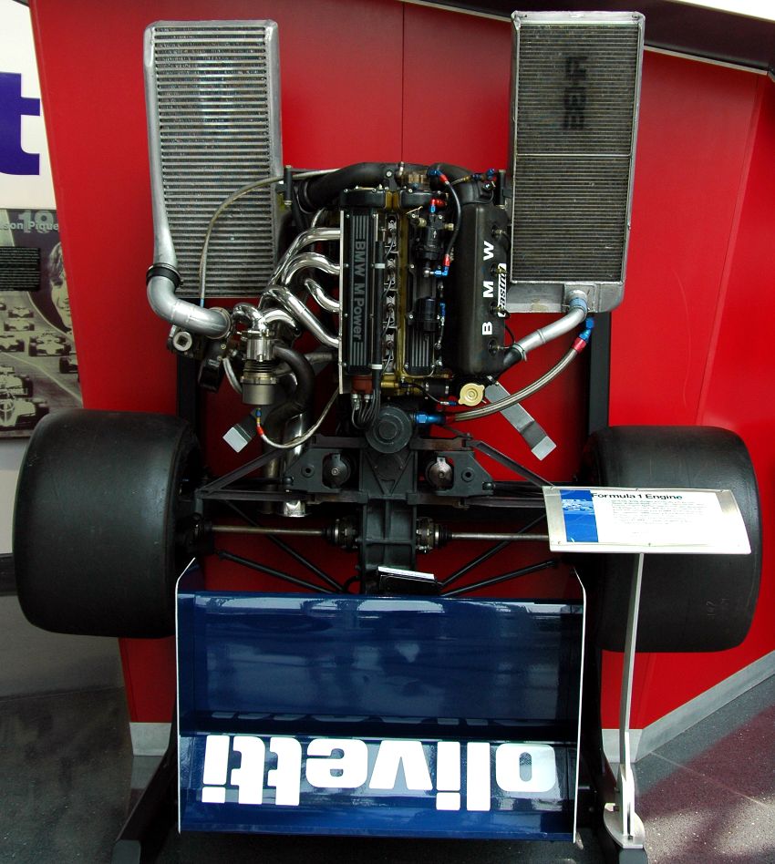
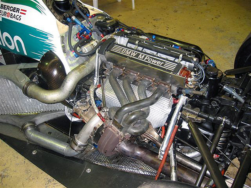
here are few intercooler pics of f1 turbo setups from the early eighties...interesting endtank design.

Honda-Tech Member
Joined: May 2008
Posts: 39
Likes: 0
Re: Intercooler end tank design
^^^ Those first two are from the BMW museum about ~15 mins from here, pretty cool stuff. Divided housing, single gate too 
As for the CFD, the group I'm in at work does a ton and I've done a bit also. CFD is 100% in the boundary conditions. Just about any program will give you a numerical answer, but it's not always easy to get an answer to the question you 'think' you are asking.
Since this is all subsonic flow, it would be interesting to assemble the rest of the intercooler in CAD and simulate the passages also. You could leave out the inner turbulators on the air passages to simplify things. I'm betting this would have a decent impact on your end tank velocity contours.
As for the CFD, the group I'm in at work does a ton and I've done a bit also. CFD is 100% in the boundary conditions. Just about any program will give you a numerical answer, but it's not always easy to get an answer to the question you 'think' you are asking.
Since this is all subsonic flow, it would be interesting to assemble the rest of the intercooler in CAD and simulate the passages also. You could leave out the inner turbulators on the air passages to simplify things. I'm betting this would have a decent impact on your end tank velocity contours.

Honda-Tech Member

Joined: Apr 2003
Posts: 988
Likes: 0
From: Montreal, Quebec, Canada
Re: Intercooler end tank design
Leebro, that's how I tested my design. I actually modelled the core with the correct amount of passages etc ... Obviously I left out the tiny fins inside, but you could see the air flow was turbulent right as is entering those passages.


Thread Starter
Honda-Tech Member
Joined: Sep 2003
Posts: 3,039
Likes: 2
From: insanity
Re: Intercooler end tank design
[QUOTE=javierb14;41028020]Bingo. its all about what you want and how much you have to spend. just a compromise really.
Those formula 1 intercoolers are designed to fit in a certain space so I am sure they aren't an ideal example to go by ,but they are interesting. Leebro I did test a full intercooler model ( just a quick thrown together model) it was really interesting seeing how much of an impact this does have. I modeled it without the inner turbulators ,but it did still have a big impact especially on the exiting end tank. BTW, I am getting ANSYS very soon so I want to compare how the simulations in fluent compare with these.
Those formula 1 intercoolers are designed to fit in a certain space so I am sure they aren't an ideal example to go by ,but they are interesting. Leebro I did test a full intercooler model ( just a quick thrown together model) it was really interesting seeing how much of an impact this does have. I modeled it without the inner turbulators ,but it did still have a big impact especially on the exiting end tank. BTW, I am getting ANSYS very soon so I want to compare how the simulations in fluent compare with these.
Honda-Tech Member
Joined: May 2008
Posts: 39
Likes: 0
Re: Intercooler end tank design
Awesome.
Glad to hear that other people care about this kind of thing. I made a tool in Excel to analyze intercooler core performance and nobody seemed to care. I'm happy to see some other people are interested in these kinds of things
https://honda-tech.com/forums/forced-induction-16/looking-some-intercooler-measurements-fin-count-thickness-etc-2695643/
Glad to hear that other people care about this kind of thing. I made a tool in Excel to analyze intercooler core performance and nobody seemed to care. I'm happy to see some other people are interested in these kinds of things
https://honda-tech.com/forums/forced-induction-16/looking-some-intercooler-measurements-fin-count-thickness-etc-2695643/

Honda-Tech Member
Joined: Mar 2006
Posts: 428
Likes: 0
From: NH, usa
Re: Intercooler end tank design
Here's a little something I did. Turbulence of the inlet is so bad that air doesn't even flow through all the tubes. Air shows huge velocity drops, and is not the same through all the tubes. This will prove to be worse with the inlet/exit tubes placed more towards the bottom end of the intercooler. I will later do fins inside the tanks and I'm willing to test any design that you guys recommend.


Honda-Tech Member
Joined: May 2008
Posts: 39
Likes: 0
Re: Intercooler end tank design
I think those results are exactly what you would expect from that tank design, but still interesting and worthwhile to see the results. It goes without saying that the inlet tank is going to be the problem, so you need to find a way to deal with the adverse pressure gradient. And, this is picking at details, but turbulence generally is descriptive of the fluid behavior at a small scale. That doubling back of the fluid you see is probably better described as "separation" or "recirculation".
Guide vanes in the end tank would be a good theoretical solution, but in practice I think you might have some issues from a fabrication stand point. A cast tank with dividers would be awesome though!
Guide vanes in the end tank would be a good theoretical solution, but in practice I think you might have some issues from a fabrication stand point. A cast tank with dividers would be awesome though!
Honda-Tech Member
Joined: Mar 2006
Posts: 428
Likes: 0
From: NH, usa

Honda-Tech Member
Joined: Mar 2006
Posts: 428
Likes: 0
From: NH, usa
Re: Intercooler end tank design
The results are in. The fancier fences perform better as I thought. The air is spread out more evenly and has a higher velocity then the bottom half of this intercooler design. Both fins seem to be an improvement over the one without fins. I can now go over and fix some of the fins for maximum flow, but by this point I think we all get the point and I would like to move on to another design. If you have exact measurements and pix, I can test something else.


Honda-Tech Member
Joined: Mar 2004
Posts: 7,434
Likes: 2
Re: Intercooler end tank design
here is a link to their site:
http://www.treadstoneperformance.com...5&phot_key=731
Core Size, 12" X 22" X 3.5/4.5"
Overall lenght 30"
3" inlet/outlet
http://www.treadstoneperformance.com...5&phot_key=731
Core Size, 12" X 22" X 3.5/4.5"
Overall lenght 30"
3" inlet/outlet
Honda-Tech Member
Joined: Mar 2006
Posts: 428
Likes: 0
From: NH, usa
Re: Intercooler end tank design
here is a link to their site:
http://www.treadstoneperformance.com...5&phot_key=731
Core Size, 12" X 22" X 3.5/4.5"
Overall lenght 30"
3" inlet/outlet
http://www.treadstoneperformance.com...5&phot_key=731
Core Size, 12" X 22" X 3.5/4.5"
Overall lenght 30"
3" inlet/outlet

Working
Joined: Dec 2001
Posts: 8,571
Likes: 6
From: Knoxville,TN U.S.
Re: Intercooler end tank design
I would like to see more on this subject and I think it is still within the realm of fabrication since people that build intercoolers will see this and it will influence future intercoolers. I know when I build my intercooler it will have fins to guide the airflow, but that is just me.

Honda-Tech Member
Joined: Apr 2007
Posts: 501
Likes: 0
From: charm city B-more
Re: Intercooler end tank design
i would like to see a dual backdoor flow test like fullrace's backdoor


dimensions 24x12x3.5 with 3in inlets an outlets ...overall lenth 30"
dimensions 24x12x3.5 with 3in inlets an outlets ...overall lenth 30"
Last edited by takata_nsxr; Dec 26, 2009 at 04:18 AM.

Honda-Tech Member
Joined: Mar 2006
Posts: 428
Likes: 0
From: NH, usa
Re: Intercooler end tank design
moved the tread to https://honda-tech.com/forums/showth...1#post41061199. I also did a backdoor style there.


Honda-Tech Member
Joined: Feb 2010
Posts: 502
Likes: 0
Re: Intercooler end tank design
your endtanks will always be perpendicular to the veins. so this one from an F1 car can be looked at the same as most intercoolers that you see today, just taller than it is long

Thread
Thread Starter
Forum
Replies
Last Post
HiAssHell
Welding / Fabrication
4
Nov 17, 2005 10:24 AM
