When you click on links to various merchants on this site and make a purchase, this can result in this site earning a commission. Affiliate programs and affiliations include, but are not limited to, the eBay Partner Network.
Does some one has the pinout diagram of which color code wire goes where ?
This information is in the image I posted. Can you see it?
Last edited by deschlong; Jul 15, 2021 at 09:38 AM.
Reason: On review, this post contained language that was possibly hurtful and I have replaced it. I apologize to OP.
Holy ****, have you not even looked at my previous post? The one where I posted the image that shows exactly the answer to this question? Is there something wrong with your browser that you can't see the image, or is it more just user error?
What was missing in your otherwise helpful post was the connector view showing the arrangement/location of the pin numbers.
I still don't follow - the post has pin numbers and corresponding wire colours. What more is needed? It's like I'm being gaslighted!
OP does not know the correspondence between pin holes in the connector and the numbers. What OP additionally may need is the accompanying service manual illustration of the connector showing the pin out.
For example, this might be important if the OP's connector pair has been depinned.
Me thinks you purposely post all service manual illustrations except the one OP actually seeks.
Ah, that's because the service manual does not have views of this junction connector, nor does the ETM. But, I've located the equivalent information elsewhere (with some difficulty) but it does need to be pieced together by OP. I've provided the info to do just this but I have failed to do it clearly enough.
Originally Posted by zeegee84
You mate is all over the place ...... I was simply asking for pinout details "which wire number goes where"
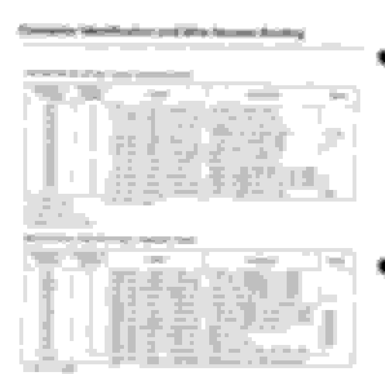
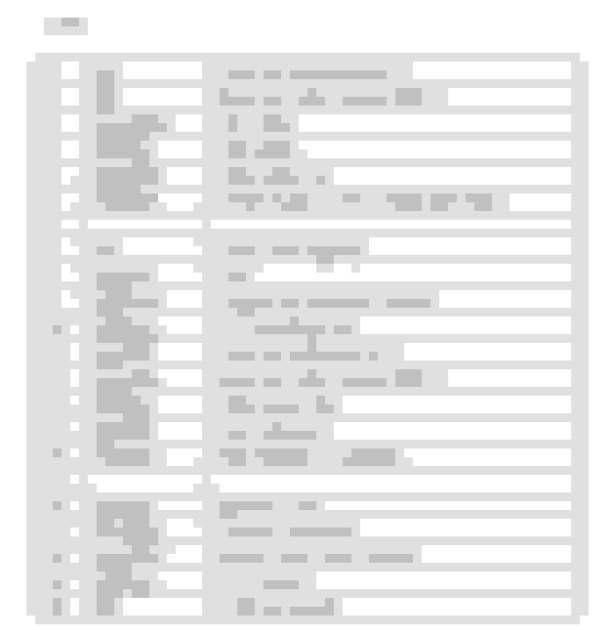
That information is in this table I posted. Connector C419 shows PIN 1 as YEL/GRN, PIN 2 as YEL/RED, etc. This informs precisely "which wire number goes where". Opening the image in a new tab will enlarge it and enhance legibility.
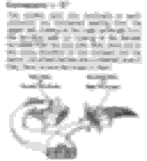
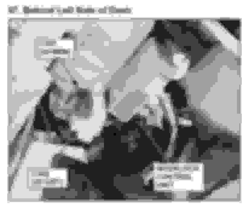
If the problem is then "which PIN is PIN 1, PIN 2, etc.", then the image below I posted earlier is helpful with this. From your photo in post #4, you see that the connectors are female. Female connectors are numbered from the wire side, beginning at the upper left. This should be all the information you require to reproduce the connector, even on the male side (C3##), with the caveat that *sometimes* different colour wires are mated though this is by far the exception.
Deschlong is correct. Earlier year Hondas did not have pinouts views as part of the ETMs like what people got accustom to like what is shown with subsequent years Hondas.
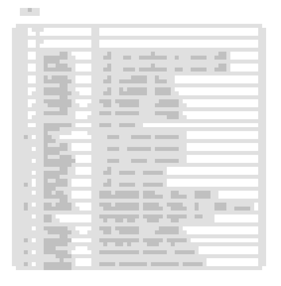
Hopefully these pics from my FSM help out. They are for a 96-00 EK Civic though, and I noticed you said EG Civic. So there is a chance these won't help at all. Sorry that I don't really know exactly what I'm looking at, or what you mean by a pinout.
I can provide the under-dashboard side as well if these pages are helpful. Lmk.
Tech8, what manual and what section in your manual did you find that table listing connections and wire color? I may have that but haven't found it yet
Edit: I'm so inspired by how hard we've gone with diargrams for such a question lol, epic
Hopefully these pics from my FSM help out. They are for a 96-00 EK Civic though, and I noticed you said EG Civic. So there is a chance these won't help at all. Sorry that I don't really know exactly what I'm looking at, or what you mean by a pinout.
I can provide the under-dashboard side as well if these pages are helpful. Lmk.
Thankyou so much buddy and everyone helping me out ....... this is the info i was looking for pin number and description ......
I am working on wiring harness these days .... honda civic ek non vtech d15z4 swap in an eg so the tower connector of both cars are different luckily i have male and female side of both ek and eg harness tower connectors with me so i can
arrange pin accordingly with this info .