When you click on links to various merchants on this site and make a purchase, this can result in this site earning a commission. Affiliate programs and affiliations include, but are not limited to, the eBay Partner Network.
I've recently acquired an 88 dual point CRX and am in the process of swapping a GSR engine and most everything I have from a somewhat decent DA build from the past, suspensions and what not.. I spent the better part of a week trying to find info that didn't involve many random wires running throughout the engine bay and wasn't looking to utilize any jumper harnesses. Also I had a difficult time finding pinout info and wiring diagrams online. Many links were available but everything seemed to be 10+ years old and most of the links were dead. Finally I went to my local Honda shop and was able to photograph all the information needed out of the original service manual. I purchased a 90-91 multi point engine harness and set about decoding both engine and chassis harnesses to create a new pinout utilizing the dual point chassis harness with the multipoint engine harness making it 100% plug and play. In addition I've added accommodations within both harnesses for Vtec and also added wiring for future oil pressure and coolant temp gauges that will all pin out in the factory plugs. At the end of the day I have what I feel is a pretty easy solution as well as a clean factory looking harness so long as you're willing to unwrap your engine harness. I don't know if anyone is interested in having this info for future or current projects but I'll happily post it and all of the pinout and wiring diagrams. So far I have completed the engine harness and am in the process of making a piggy back harness for the chassis side as I am unwilling to unwrap the chassis harness.
Dual Point Fuel Injection Pinout Plug 210 Passenger Side
Plug C210 passenger side firewall
Apologies for the format below but it was difficult to get it to lay out any other way. Chassis side will be listed above and engine side will be listed below. On the engine side the letter and number that follow description are for the coinciding plug found on the engine harness in the wiring diagram.
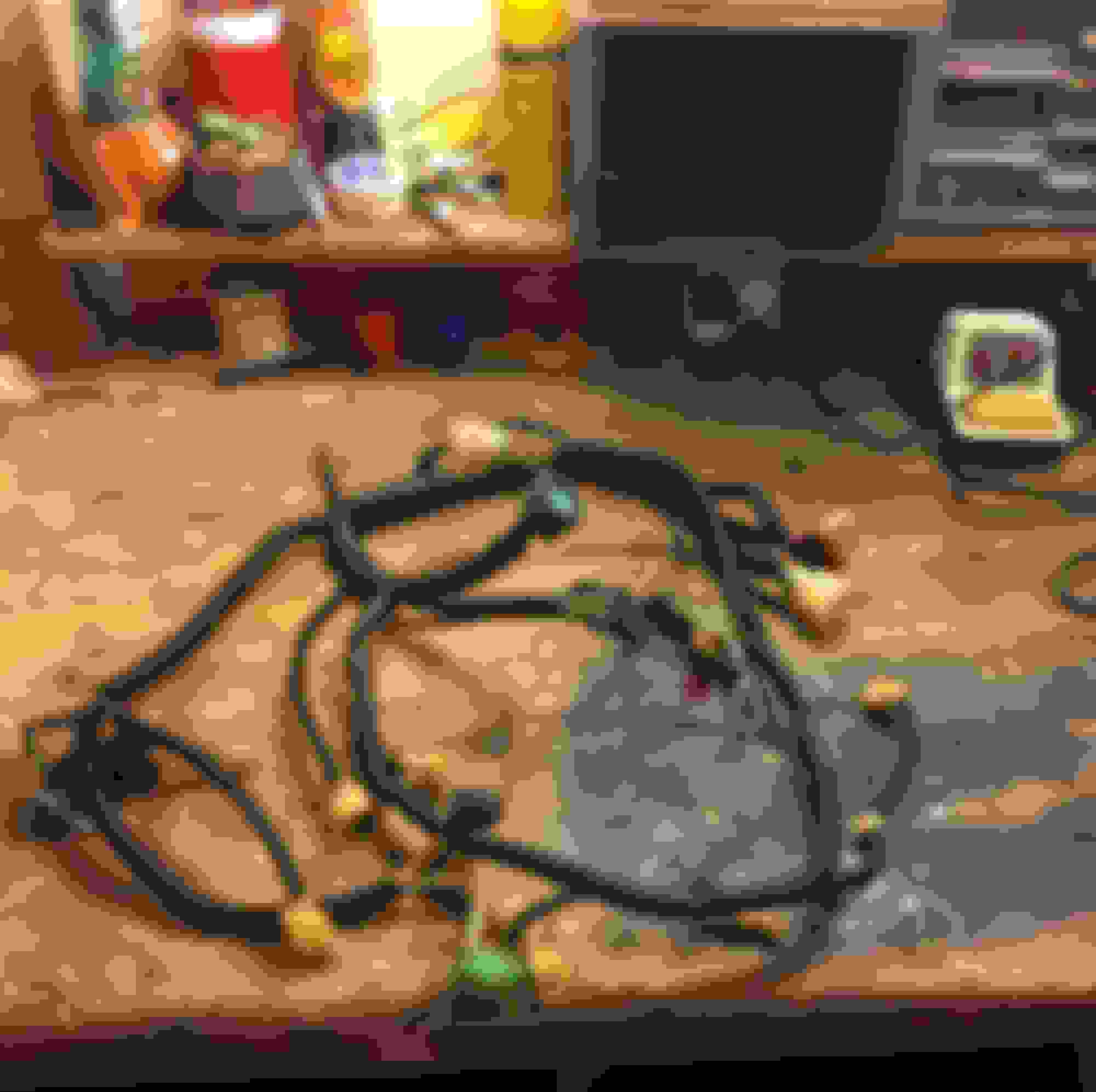
That's both harnesses decoded. In re-pinning I had to rob the dual point harness of a few plugs to make things work. I have my engine harness completely built and as stated in the original post, I have stubbed out additional wires for both the Vtec oil pressure switch and Vtec solenoid plugs. I will end up purchasing the 1 pin connector for the Vtec solenoid plug from Rywire as they have a pretty great selection of empty connectors. In addition I've also stubbed out two wires within the engine harness to accommodate future oil pressure and coolant temp sensors. Pictured below is the unwrapped engine harness. I used small zip ties to hold the overall form of the harness and keep it organized during disassembly. Anywhere that wiring branched off from the main run of wires I also made sure to add zips. The DA Integra donor car also had an OBD0 to OBD1 jumper harness and in an attempt to lose all jumpers I also took the time while the harness was apart to solder in the OBD1 distributor plug. Originally I tried to pin in the OBD0 pins to that connector but the pins are not the same so I had to cut and solder these connections. Depending on which distributor you have there is plenty of info online for re-pinning this connector so I won't go into detail on that. In addition I also soldered the four RED/BLK injector wires into the YEL/BLK Injector resistor wire as is required with the OBD0 to OBD1 conversion. I also needed to move three wires within the Multi Point engine harness from the passenger side to the driver side because they stub out on that side of the chassis harness in connector C313. In an attempt to keep chassis harness modification to an absolute minimum, to avoid the obvious headache I made the decision to modify it within the engine harness. This change made room for my Vtec wiring on the passenger side connector C212 which had originally been full. I also changed the the driver side engine harness C313 from an 8 pin connector to the 14 pin connector that is on the chassis. I will go over all of this in the next post. I have not yet built the piggy back under dash harness so I am not comfortable posting my completed hybrid pin out until I've finished the under dash portion.
I originally thought this task was going to be daunting but once I was able to put both sheets side by side and see what was the same and what was different between the two harnesses, making the necessary changes became quite easy. It's only matching colors and numbers at the end of the day and I'm sure anyone with the ability to create a Honda-tech login can do that. The end result will be an engine bay that has a factory appearance with no stray wires and with all pins and connectors available within both engine harnesses, it really isn't very expensive either. Only a bit tedious and time consuming. Pictured below is also the completed engine harness although I ran out of tape that night so no calling me out on that. Also as I'm sure you can see I've not added the plugs for the Vtec additions but will do so as soon as I order the necessary 1 pin connector from Rywire.
Had some delays with the swap so I've not posted the finished schematic yet as it is obviously untested. The car is going in the week for some interior monkey bars and after that's been completed the swap should commence.