

The New Header test thread

Thread Starter
Honda-Tech Member
Joined: Jul 2005
Posts: 1,734
Likes: 2
From: Canada
pretty straightforward, im going to make 3 nearly identical headers to test back to back to back when it comes tuning time.
I will elaborate further on my idea but first, i'm curious what others would try if they could make 3 headers for them self and compare them?
Which variables would you play with and why? what would remain constant?
There has already been a lot of discussion on length and we all know about how that effects the engine so let's take the discussion elsewhere


Honda-Tech Member
Joined: Feb 2014
Posts: 415
Likes: 0
From: Atlanta, GA
Buy pipemax. Profit.
If length is out of the question (for some reason) then the only other options are stepping primaries, collector length, and collector design.
If length is out of the question (for some reason) then the only other options are stepping primaries, collector length, and collector design.
Honda-Tech Member
Joined: Mar 2009
Posts: 757
Likes: 2
From: NW Ohio
Actually it d keep merge angle constant. Whether or not using 4-1 or 4-2-1 I'd say finding a narrow angle you could better test benefits of pipe material and thicknesses or bend radius diameter. Others have done this work but their designs were not released and products no longer on the market.
Thread Starter
Honda-Tech Member
Joined: Jul 2005
Posts: 1,734
Likes: 2
From: Canada
thank you all for the input.
in theory, if you increase cross sectional area of a flow you lower pressure. given all other things equal, 2 headers the same length with different diameter primaries will have 2 different volumes. the exhaust pulse will not move through the runners at the same velocity, however the pressure wave traveling in each header will be the same because it is fixed at the speed of sound. therefore the 2 different headers will act like they are different lengths because the exhaust pulse and the pressure wave will not be phased exactly the same.
the plan? make 3 different headers with the diameters stepped at different points so that i effectively have 3 very similar headers of equal length, each with a different volume. ideally, there will be enough difference when it comes time to test them that each one responds to my setup differently. The intake im using is an ITB setup and i will make a couple extra sets of trumpets at different lengths so that i can try and get the intake and exhaust in phase.
maybe i should make one non-stepped header for a kind of "baseline" comparison but im not sure how i could most effectively learn from it because it would have more than just a volume difference with the others.
also there is the idea that the number of bends and overall shape of the header will effect it in some way which could also be looked at.
lastly, after i test the 3 im going to make a 4th out of stainless based on what i have learned.

Thread Starter
Honda-Tech Member
Joined: Jul 2005
Posts: 1,734
Likes: 2
From: Canada
i guess people dont like talking about this kind of thing as much as i do. owell
last update 1 header is finished maybe ill make a thread when i test them i doubt it tho.

last update 1 header is finished maybe ill make a thread when i test them i doubt it tho.

Trending Topics

Honda-Tech Member
Joined: Feb 2014
Posts: 415
Likes: 0
From: Atlanta, GA
Pipemax already has a very good calculator for primary length/size and even step sizes. I don't build headers but I assume the nationally known guys are using it since the program is incredibly good especially for such a small cost.
I'd be very interested to see some dyno graphs but realistically since so many variables go into the "ideal" header it would be even more interesting to see these headers (once you're done) on several other engines with displacement and peak HP RPM differences.
Honda-Tech Member
Joined: Aug 2005
Posts: 1,181
Likes: 0
From: New York
x2.
Pipemax already has a very good calculator for primary length/size and even step sizes. I don't build headers but I assume the nationally known guys are using it since the program is incredibly good especially for such a small cost.
I'd be very interested to see some dyno graphs but realistically since so many variables go into the "ideal" header it would be even more interesting to see these headers (once you're done) on several other engines with displacement and peak HP RPM differences.
Thread Starter
Honda-Tech Member
Joined: Jul 2005
Posts: 1,734
Likes: 2
From: Canada
i guess i just wanted to have my "everybody look at me moment" more than anything. I was hoping a couple pics would generate some discussion and i could try and predict issues/problems/shortfalls and maybe make sure my research provides the best hp return for the invested time and money. I'm aware posting the results will get a lot more attention, at that point most of the input will be useless to me
Anyways i guess some people did raise an eyebrow at the whole theory vs reality question. The bulk of information which is backed by real world data MOSTLY all applies to larger sized cylinders operating below 100% VE. obviously our reality is a small engine capable of well over 100% VE so how does that effect the header requirements? people who work with motorcycles probably have some formulas better suited to small engines but maybe too small for our needs, and that information doesnt seem to be widely available.
Anyways i've done some more reading and have some new questions to ponder. A little background first, one reason for the step in diameters of the primaries is creating properly timed pressure waves. at the first step, some of the amplitude of the traveling sound wave (proportional to total change in c.s.a.) is reflected back towards the exhaust valves. the idea is to have this first wave return sometime before the intake valve opens because it helps to remove exhaust gases. the length to the first step therefore must match the timing of the exhaust valve opening as well as the desired rpm for the effect to occur.
My question is this, would it be better to have the returning wave reach the valve when the cylinder pressure and pressure ratio with the exhaust port is very high? or sometime after the piston has already moved away from BDC and the cylinder and exhaust port pressure ratio is closer to 1:1? what about right at BDC so that the cylinder pressure is still as high as possible during the final degrees of the power stroke (where its mostly useless anyways) and then lower after BDC to limit pumping losses? OR does having 2 diametric steps allow for both (each with less amplitude) waves to hit the exhaust valve while it is exhausting as a "best of both worlds" scenario?
Thoughts? what effect does the first reflected wave have on local particle velocity and/or local speed of sound?
Thread Starter
Honda-Tech Member
Joined: Jul 2005
Posts: 1,734
Likes: 2
From: Canada
I have a mostly stock h22a4 and a decent 88X95 build which will be tested although i dont suspect the stock engine will like it very much
Honda-Tech Member
Joined: Aug 2004
Posts: 4,167
Likes: 2
From: Atlanta
i guess i just wanted to have my "everybody look at me moment" more than anything. I was hoping a couple pics would generate some discussion and i could try and predict issues/problems/shortfalls and maybe make sure my research provides the best hp return for the invested time and money. I'm aware posting the results will get a lot more attention, at that point most of the input will be useless to me
Anyways i guess some people did raise an eyebrow at the whole theory vs reality question. The bulk of information which is backed by real world data MOSTLY all applies to larger sized cylinders operating below 100% VE. obviously our reality is a small engine capable of well over 100% VE so how does that effect the header requirements? people who work with motorcycles probably have some formulas better suited to small engines but maybe too small for our needs, and that information doesnt seem to be widely available.
Anyways i've done some more reading and have some new questions to ponder. A little background first, one reason for the step in diameters of the primaries is creating properly timed pressure waves. at the first step, some of the amplitude of the traveling sound wave (proportional to total change in c.s.a.) is reflected back towards the exhaust valves. the idea is to have this first wave return sometime before the intake valve opens because it helps to remove exhaust gases. the length to the first step therefore must match the timing of the exhaust valve opening as well as the desired rpm for the effect to occur.
My question is this, would it be better to have the returning wave reach the valve when the cylinder pressure and pressure ratio with the exhaust port is very high? or sometime after the piston has already moved away from BDC and the cylinder and exhaust port pressure ratio is closer to 1:1? what about right at BDC so that the cylinder pressure is still as high as possible during the final degrees of the power stroke (where its mostly useless anyways) and then lower after BDC to limit pumping losses? OR does having 2 diametric steps allow for both (each with less amplitude) waves to hit the exhaust valve while it is exhausting as a "best of both worlds" scenario?
Thoughts? what effect does the first reflected wave have on local particle velocity and/or local speed of sound?
Anyways i guess some people did raise an eyebrow at the whole theory vs reality question. The bulk of information which is backed by real world data MOSTLY all applies to larger sized cylinders operating below 100% VE. obviously our reality is a small engine capable of well over 100% VE so how does that effect the header requirements? people who work with motorcycles probably have some formulas better suited to small engines but maybe too small for our needs, and that information doesnt seem to be widely available.
Anyways i've done some more reading and have some new questions to ponder. A little background first, one reason for the step in diameters of the primaries is creating properly timed pressure waves. at the first step, some of the amplitude of the traveling sound wave (proportional to total change in c.s.a.) is reflected back towards the exhaust valves. the idea is to have this first wave return sometime before the intake valve opens because it helps to remove exhaust gases. the length to the first step therefore must match the timing of the exhaust valve opening as well as the desired rpm for the effect to occur.
My question is this, would it be better to have the returning wave reach the valve when the cylinder pressure and pressure ratio with the exhaust port is very high? or sometime after the piston has already moved away from BDC and the cylinder and exhaust port pressure ratio is closer to 1:1? what about right at BDC so that the cylinder pressure is still as high as possible during the final degrees of the power stroke (where its mostly useless anyways) and then lower after BDC to limit pumping losses? OR does having 2 diametric steps allow for both (each with less amplitude) waves to hit the exhaust valve while it is exhausting as a "best of both worlds" scenario?
Thoughts? what effect does the first reflected wave have on local particle velocity and/or local speed of sound?
I think ultimately, exhaust tuning is essentially trying to create the "inertia supercharger" effect at a desired rpm for as long as possible, which I think is the direct cause or a main reason for over 100% VE at any given point. That point where the engine sings this wonderful 8k rpm note when your at 125 hp/liter. I bet one could get an idea of exhaust tuning and design by observing the map sensor values during peak TQ.
As far as exhaust pressure wave tuning and all that, im clueless lol.
Thread Starter
Honda-Tech Member
Joined: Jul 2005
Posts: 1,734
Likes: 2
From: Canada
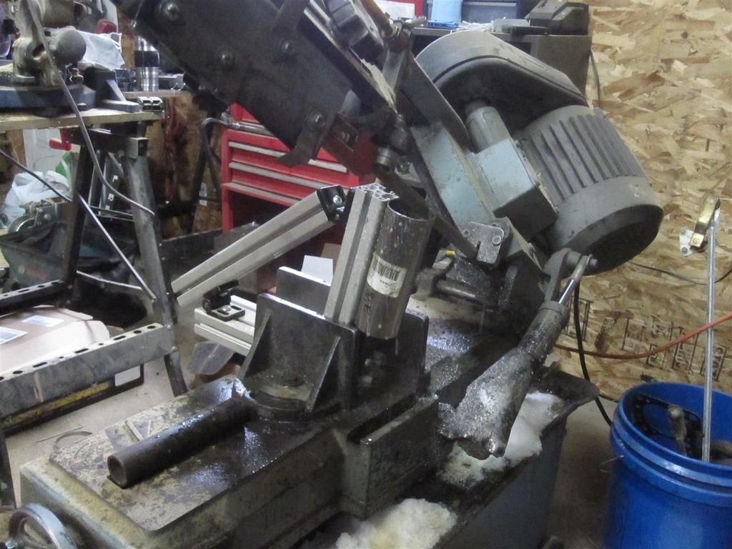
as far as cutting on the bandsaw goes, there is a piece of 1" sq tubing inside of the tube which is being cut. it has 2 bolts in the bottom that go into T nuts in the extrusion slot. when you tighten them it pulls the tube tight into the channel of the extrusion.
The Map sensor is too far away and doesnt respond quickly enough to tell you anything about what is happening on the exhaust side. we are talking about pressure that rises and falls at very fast rates. If the map sensor signal comes from close to the head you can get a good idea of what is happening on the intake side but there is no real way to tell from this data alone if the average pressure values are a result of the exhaust pressure being lower and increasing the velocity on the intake side, or if the intake inertia is just higher because the intake side is working better. furthermore it could just be that the cam timing is way off and when all the air is essentially forced back up the intake runner when the valve closes, it registers at the map sensor as a higher pressure relative to the atmospheric pressure.
The OEMs don't need to or choose not to use expensive headers for a number of reasons, that's a different subject altogether.
Also, yes I'm familiar with the VR6, here is a pic of the last header I made in the summer time for a good buddy of mine.


Thread
Thread Starter
Forum
Replies
Last Post
VtecKiDD
All Motor / Naturally Aspirated
226
Nov 22, 2010 04:38 AM
TypeR0149
Acura Integra Type-R
20
Dec 10, 2001 10:19 PM