

fuel gauge wiring with pics?

Thread Starter
Honda-Tech Member
Joined: Mar 2003
Posts: 899
Likes: 0
From: Monroe, NC, USA
Ok so I have a stripped race car
and I need a way to be able to tell the amount of fuel in the tank
I went to the junkyard and pulled a stock fuel gauge
it has 3 screws on the back of it for electrical connection
I looked at the fuel tank and there are 2 plugs
one is the fuel pump controls and wiring
and there is a 2nd plug that has 2 wires that the previous owner snipped off
Im sure there is a simple connection I can make to have a reading on my fuel tank
anyone familiar with whats what and what goes where?
Hysterically Calm


Joined: Jan 2013
Posts: 10,439
Likes: 597
Okay now we have a 94 hatch with a chevy small block and the dodge rear end.....
Come on man, you say race car so how can we magically know what motor or mods are swapped in for the track. And if you say stock, we still don't know what trim level so it could be 1 of 4 engines for the USDM 92-95 hatch.
How do we know you don't have a walbro fuel pump to power 800CC injectors on your turbo K20 swap.
All car information is very important when asking for technical help. Anything less doesn't get you any reasonable answers.
Hysterically Calm
Joined: Jan 2013
Posts: 10,439
Likes: 597
Also just making the point of the rules for the model specific tech forum, all car information is supposed to be present.
Trending Topics
longest project ever
Joined: Sep 2009
Posts: 3,494
Likes: 2
From: on the south side of dixie, 1986 Accord Hatch
Would the sender stay the same if there was an aftermarket fuel pump put in? I assumed the sender was incorporated into the pump. I haven't actually looked at the pump and sender setup in my car yet. My focus has been main in the engine compartment.
Also just making the point of the rules for the model specific tech forum, all car information is supposed to be present.
Also just making the point of the rules for the model specific tech forum, all car information is supposed to be present.
Hysterically Calm
Joined: Jan 2013
Posts: 10,439
Likes: 597
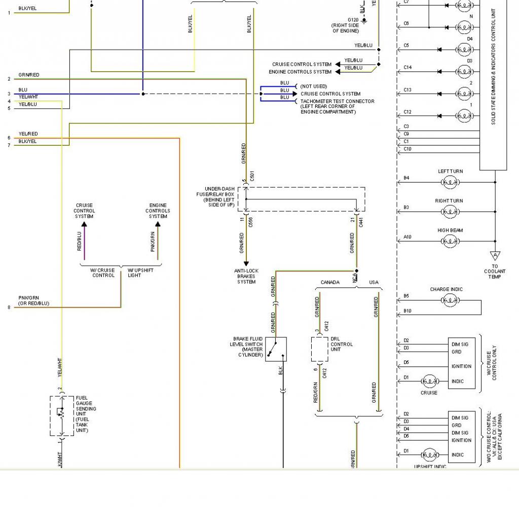
If it's stock, then the brown 2 pin connector C564 with Yellow/Green wire and a Black wire (which runs to ground G551) is your fuel pump.
The brown 3 pin connector C563 with what appears to be only 2 live wires, a Yellow/White wire and a Black/White wire (that runs to ground G551) is your fuel gauge sending unit. The Yellow/White wire traces to connector C502 and continues up to connector C511 where it looks like it plugs into the gauge assembly.
The fuel guage readings in the manual shows E = to 105-110 ohms of resistance while 1/2 tank = 25.6-39.5 ohms and a full tank shows a mere 2-5 ohms of resistance.
Even though the C563 is a 3 pin plug, I only see two active wires in the manual.
longest project ever
Joined: Sep 2009
Posts: 3,494
Likes: 2
From: on the south side of dixie, 1986 Accord Hatch
OP you will have to search, but I have seen some aftermarket gauges that can be programmed to work off of any sender, providing you know the OHM range
Thread Starter
Honda-Tech Member
Joined: Mar 2003
Posts: 899
Likes: 0
From: Monroe, NC, USA
Ok so I'm in desperate need of a fuel gauge on my car car
1994 civic hatch
Here is a pic of the 3 connections on the rear of the gauge
And also a pic of various wires on the sending unit
What wires connect to where in order for this gauge to operate?
Is there a diagram I need to reference?
1994 civic hatch
Here is a pic of the 3 connections on the rear of the gauge
And also a pic of various wires on the sending unit
What wires connect to where in order for this gauge to operate?
Is there a diagram I need to reference?

Honda-Tech Member
Joined: Sep 2014
Posts: 34
Likes: 2
Yes, when I get home I will post related wiring diagrams.
You do not wire the sending unit directly to the gauge. The wiring goes to the plug behind the cluster then via printed circuit to the gauge itself.
You do not wire the sending unit directly to the gauge. The wiring goes to the plug behind the cluster then via printed circuit to the gauge itself.
Thread Starter
Honda-Tech Member
Joined: Mar 2003
Posts: 899
Likes: 0
From: Monroe, NC, USA
In my race car in don't have any of that
I was gonna wire it direct to the gauge because
I can't tell how much fuel in have and actually ran out of gas on the track
Doh!
I was gonna wire it direct to the gauge because
I can't tell how much fuel in have and actually ran out of gas on the track
Doh!
Thread Starter
Honda-Tech Member
Joined: Mar 2003
Posts: 899
Likes: 0
From: Monroe, NC, USA
Getting some good information so far
Seems there would be a schematic that tells what each of those 3 connections on the rear of the gauge are
Seems there would be a schematic that tells what each of those 3 connections on the rear of the gauge are

Global Moderator

Joined: Jul 2004
Posts: 6,058
Likes: 514
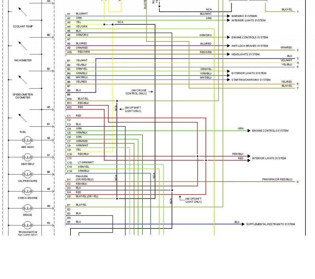
Here is a description of how the fuel gauge works:
The fuel gauge has two intersecting coils wound around a permanent magnet rotor. Voltage applied to the coils, through Under�dash fuse no. 15 via Yellow wire, generates a magnetic field. The magnetic field, controlled by the fuel gauge sending unit, causes the rotor to rotate and the gauge needle to move. As the resistance in the sending unit varies, current through the gauge coils changes. The gauge needle moves toward the coil with the strongest magnetic field.
Fuel Gauge Readings:
E � 105-110 ohms
� � 25.5-39.5 ohms
F � 2-5 ohms
This is what it looks like to me.

Trial User
Joined: Jul 2017
Posts: 1
Likes: 0
Thanks for this old topic, i managed to diagnose and solved my old civic 1994 from your cable diagram. I connected the broken spool wire behind the fuel indicator. May be broken by turning the bolt too tight. Sorry for my bad translate, maybe. Hehe im indonesian.

Thread
Thread Starter
Forum
Replies
Last Post
Linked
Honda Civic / Del Sol (1992 - 2000)
7
May 31, 2009 07:00 PM
b.d.racing
Honda CRX / EF Civic (1988 - 1991)
8
Apr 12, 2006 08:09 PM