When you click on links to various merchants on this site and make a purchase, this can result in this site earning a commission. Affiliate programs and affiliations include, but are not limited to, the eBay Partner Network.
So the issue with this install was only the temp gauge, were you able to confirm that? Can you show the location of where you soldered it to?
These lights: http://img43.imageshack.us/img43/658...oncluster1.gif
are all controlled by a cpu so you have to find then on the circuit board desolder them, and solder a wire directly to the led. This bypasses the original signal.
You also have to do this for the trunk(controlled by multiplier) and headlights.
The image above show the temp. There are 3 pins on the motor and one says "unit". You desolder this one and make sure it doesn't touch anything else. Use a glue gun to isolate it and solder a new wire to it.
Its not a really good image thats why I asked. I know you're probably done with the swap. Hopefully someone else thats doing the same thing will shine some light to this with images of the location. Gj though! I've been wanting to do this.
Any write-up on this? Been waiting for years! I did the wired diagram already. Temp is now going up. I would want to know more about the "Desolder and nail polish" or "Desolder and solder them to LED". I want to know more. A full write-up would be appreciated.
Same here been waiting we just need better pics hope someone is out there who is part of this site to help us out. Thanks in advance
I been soldering wire to led . TAs far as the temp unit wire I de soldered it it and removed it from the board. Do I solder a new wire to the "unit" leg or the board.
Bring back from the dead! Trying to find the full diagram that shows everything, Please help!!
How did you get the temp gauge seperated from the cluster? Remove the needle?? Thanks in advance
I recall the OP cut the signal from the rest of the cluster and solder the temp gauge wire directly to the cluster. Keep digging and you'll see an image floating around here somewhere.
I am currently on this Swap. Doing it to my 96 Civic Coupe. It has been a headache doing everything from scratch. I am Taking all the detailed pictures as I go. If all goes smooth, i ll be posting all the details, start to finish. As NO THREADS OR VIDEOS anywhere are complete.
I ll be making a youtube guide for all of us, so that this topic gets soeted once and for all 😅
Fingers crossed.
Uploading a picture of my progress until now.
See you soon
I have tried to explain everything PCB wise in this one
will be uploading more regarding EK cluster loom and pinouts for this cluster, what goes where.
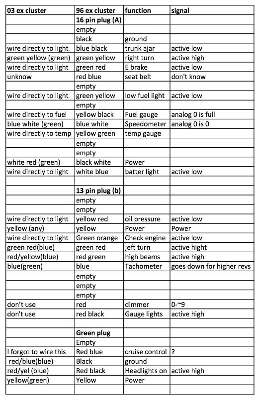
I have attached all the Pinouts for both 96 & 03 civic cluster plugs.
I added 100 ohm- 1 watt resistor in series to the Unit wire of Temp gauge.
Have to know exact resistance for the Fuel gauge.