

Custom Intake Manifold Velocity Stack Questions


Thread Starter
Honda-Tech Member
Joined: Feb 2010
Posts: 583
Likes: 0
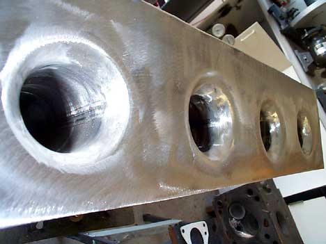
Building a custom manifold and wondering the difference between having velocity stacks inside the plenum (first picture) vs having a merge after the plenum (second picture) or where the runner itself merges from say 2" down to
1.5" to act like a velocity stack (not exact numbers just to get an idea). I know having velocity stacks helps, but I don't see a major difference between the two. If the stacks stick up in the plenum it seems like the area below the stack would be wasted volume.

1.5" to act like a velocity stack (not exact numbers just to get an idea). I know having velocity stacks helps, but I don't see a major difference between the two. If the stacks stick up in the plenum it seems like the area below the stack would be wasted volume.
Honda-Tech Member
Joined: Jan 2005
Posts: 5,641
Likes: 0
From: Lower Right Hand Corner, PA
The purpose of the velocity stack is to reduce turbulance and friction as the air enters the runner. The above picture is competely rounded, allowing it do draw air from all sides in a completely smooth manner. The beveled plate is still only rounded for 90*, which means that air running to the intake from the plate will flip and roll as it goes into the intake.
Hard to draw a picture with words though, a fluid dynamic simulation would illustrate better. It's better to be out into the plenum a little bit so you can draw air from the plenum, and not from the face of the plenum.
Hard to draw a picture with words though, a fluid dynamic simulation would illustrate better. It's better to be out into the plenum a little bit so you can draw air from the plenum, and not from the face of the plenum.
GDD Lonely Krew
Joined: Feb 2005
Posts: 860
Likes: 2
From: Reseda, CA, USA
I dont know the exact science behind it but the area below the stacks is there for a reason, it is not wasted volume. They raise the stack to allow the runner to ingest air that is not turbulent as it would be against a flat surface. I dont have the right terminology to describe this but maybe one of our Og's can come in and shine some light on this for us. If you have ever seen flow analysis diagrams of manifolds you will better understand what is going on here..
Honda-Tech Member
Joined: Aug 2012
Posts: 196
Likes: 9
From: Philadelphia
The purpose of the velocity stack is to reduce turbulance and friction as the air enters the runner. The above picture is competely rounded, allowing it do draw air from all sides in a completely smooth manner. The beveled plate is still only rounded for 90*, which means that air running to the intake from the plate will flip and roll as it goes into the intake.
Hard to draw a picture with words though, a fluid dynamic simulation would illustrate better. It's better to be out into the plenum a little bit so you can draw air from the plenum, and not from the face of the plenum.
Hard to draw a picture with words though, a fluid dynamic simulation would illustrate better. It's better to be out into the plenum a little bit so you can draw air from the plenum, and not from the face of the plenum.
With the rolled 90, only the flow at the edge is pulled in smoothly. The rest of the air in the mass hits the flat edge and swirls over itself, creating turbulence.

Honda-Tech Member
Joined: Apr 2011
Posts: 530
Likes: 0
From: Kingston, Ontario
so if one was determining the plenum volume to be used (in addition to all other variables)....
would you consider the area below the height of the velocity stack as plenum volume or is is considered more of a buffer area and thus the air in that area stagnant?
would you consider the area below the height of the velocity stack as plenum volume or is is considered more of a buffer area and thus the air in that area stagnant?
Honda-Tech Member
Joined: Jan 2005
Posts: 5,641
Likes: 0
From: Lower Right Hand Corner, PA
It is still considered plenum volume area. Just because the air is on the opposite side of the inlet, doesn't mean it's going to just sit there and do nothing.
Remember, any fluid will seek a pressure equilibrium. When you remove air from an area, it will be filled with more air from all directions, until there is no more air to fill with. In other words, those velocity stacks are actually pulling air from all directions in the IM, which is why they are completely rounded.
There is no perfect completely non turbulant way to get air down the runner, but the top picture is a pretty damn good way to do it.

Thread
Thread Starter
Forum
Replies
Last Post
NeverLift
All Motor / Naturally Aspirated
18
Aug 28, 2009 04:26 PM
boosted hybrid
Forced Induction
70
Aug 13, 2006 04:36 PM