

Life was simpler when I didn't believe in sway barz...

Thread Starter
Honda-Tech Member
Joined: Feb 2000
Posts: 4,049
Likes: 2
From: Snowwhitepillowformybigfathead
...but I don't not believe in them anymore...
Scott, who so wants to get the rear sway bar done...so he can start on the front...
Scott, who so wants to get the rear sway bar done...so he can start on the front...
Honda-Tech Member


Joined: Aug 2008
Posts: 701
Likes: 5
From: Ghent, Flanders Fields, Belgium
Serious stuff. Very. 
Is this a one-diameter-only setup? Custom LCAs?
Roll resistance with this thing should be HUGE, not?
Planning some simular design up front?
Qs, Qs, ...

Is this a one-diameter-only setup? Custom LCAs?
Roll resistance with this thing should be HUGE, not?
Planning some simular design up front?
Qs, Qs, ...
Honda-Tech Member
Joined: Feb 2007
Posts: 441
Likes: 0
From: Melbourne, Victoria, Australia
 .
.
Trending Topics
a.k.a. Komodo
Joined: Jun 2009
Posts: 847
Likes: 2
From: England
Interesting stuff Scott, do you have a thread running detailing the work on the rest of your car?
Is that strut rod just a stand in item for the actual damper or are you creating an inboard cantilever system?
Is that strut rod just a stand in item for the actual damper or are you creating an inboard cantilever system?
Honda-Tech Member
Joined: Dec 2005
Posts: 542
Likes: 0
From: Troy, NY
That’s awesome! always love to see this type of grassroots ingenuity.
Wish there were more threads on HT like this. Definitely what I would like to
be doing if I had a work space and was good with the maths!
Would love to see this rest of the car as well
Wish there were more threads on HT like this. Definitely what I would like to
be doing if I had a work space and was good with the maths!
Interesting stuff Scott, do you have a thread running detailing the work on the rest of your car?


Honda-Tech Member
Joined: Jan 2004
Posts: 3,057
Likes: 0
From: Baltimore, MD
Looks like good work. what you are gaining in motion ratio might be lost due to decreased stiffness from a longer arm. Why not extend the swaybar wider and get more of a 90* angle on LCA and swaybar? That way the sway arm will be shorter.
What was the reason for mounting the swaybar like this anyway? With the bar on the subframe yeah you have a risk of tearout, but you can brace it up and you get more stiffness/thickness because the arms are even shorter.
What was the reason for mounting the swaybar like this anyway? With the bar on the subframe yeah you have a risk of tearout, but you can brace it up and you get more stiffness/thickness because the arms are even shorter.
Honda-Tech Member
Joined: Aug 2008
Posts: 701
Likes: 5
From: Ghent, Flanders Fields, Belgium
Honda-Tech Member
Joined: Jun 2002
Posts: 3,569
Likes: 0
From: MA
Very nice Scott. If I may...
The reason for the shorter center section and splayed arm ends is likely a tire fitment concern. At any rate, the difference of adding a longer center section and having the bar ends come off at a 90* angle will result in a softer bar rate. The virtual arm length would be unchanged, and with such beefy arm ends the flex in those arm ends is pretty small.
Scott, did you shoot for a bar rate close to the speedway setup you had before? Did you compensate for the massive rate loss you get with the stock attachment to the LCA? That bar looks quite a bit bigger then what I swagged for a bar diameter with a 1:1 motion ratio.
Interested in your plans for the front bar. That stock pretzel is annoying the crap out of me, and at 12lbs, it's doing nothing for the diet the car is on. I'm not as willing to chop up the car as you are though.
Honda-Tech Member
Joined: Jan 2004
Posts: 3,057
Likes: 0
From: Baltimore, MD
You're right. I over looked the fact that a longer bar (of same diameter) would be softer.
I still prefer a simpler setup with right angles on the bar and lca. This focuses the force into torsion on the bar rather than the bending moments induced by having a splayed arm (although they are small) I just like the simpler more efficient design. Bringing the bar closer to the lca (like on the subframe) will shorten the arm and make the setup stiffer.
I still prefer a simpler setup with right angles on the bar and lca. This focuses the force into torsion on the bar rather than the bending moments induced by having a splayed arm (although they are small) I just like the simpler more efficient design. Bringing the bar closer to the lca (like on the subframe) will shorten the arm and make the setup stiffer.
Thread Starter
Honda-Tech Member
Joined: Feb 2000
Posts: 4,049
Likes: 2
From: Snowwhitepillowformybigfathead
There's not that much to see on the rest of the car. It's pretty unremarkable. There are pics in prior threads of things like my pedal and steering column setups.
NO! That little peice of all-thread isn't a pushrod for a rocker setup! There'd be nothing much to gain with that unless I developed a fetish for a lower/higher/better motion ratio for reasons having to do with dampers and limited wheel displacement which would probably be inapplicable here.
So about the bar. Giant pain in the *** packaging wise. The deletion of the stock rear caliper and giant e-brake protrusion made possible the layout I selected. The mounting pad placement is based on where the existing structure is. I could have run a larger carrier tube for bar in the same location and gotten a more outboard location for the bearings, but I chose not to mostly for philosophical reasons (keep it more bolt on). Just in case you don't know what you're looking at, that last pic shows both the bearing carrier and the mating shoe that goes inside the frame channel. I welded a central boss in the shoe and cut a hole above it in the trunk floor in case I wanted to run a strut to the shock tower if I wanted more vertical stiffness, but my friends who've seen it don't think that's necessary.
The bar is from Speedway Engineering and is 5/8 inch diameter. The bosses I welded into my arms started life as steering couplers from Speedway Motors. There being no standard for splines you need to send a sample boss to SE to get the bar spline cut to mate, which they will do. Arms are at about 45 degrees and then the pickup flange for the pushrod gets mounted at 45 degrees to the arm, so that it swings in a plane and not a cone. The rate of this setup as I calculate it is around 550 ft*lb/degree, or around 25% of my total rear roll stiffness (the percentage recommended by my current chassis engineering guru (ret) (dec)). The stock setup? So hard to calc or measure, the offset mounting and LCA twist factor muddying up the water - double at around 1000 ft*lb/degree?
The rod moves from the inboard forward cranny of the TA at full droop toward the outside coming fearfully close to the hose fitting on the caliper at 2 inches bump. It's a tight fit. A high misalignment rod end is required on the bottom end becase there's alot of angular change in the TA. Isn't that a great hardpoint just waiting to be used?
What else? Ah, the orignal setup. Terrible. But they got the job done, clearing things like exhaust and remote fuel filler piping (deleted on my car). Who cares about motion ratio for springs and bars anyway. But that offset mounting stock had to go, and then you're left with a very very short arm and a very short link, and a need for another hole in the top of the LCA, or a boss on the bottom of the LCA and a Subaru-like horseshoe shaped link - pass on that.
Oh, and the simultaneous engineering and manufacture has been a succession of "oh crap" and "Eah, I can still make that work" - a joy.
Scott, who is in the doldrums between conceptual completion and actual completion...
 Test fitment shots.
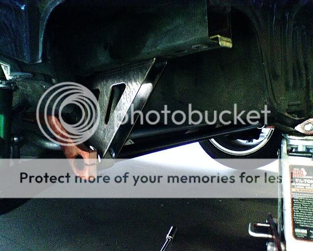

Honda-Tech Member
Joined: Jan 2008
Posts: 386
Likes: 1
From: Wappinger Falls, New York, USA
...motion ratios are nice, but sometimes they don't mean much when you add in, or consider, how much friction/spring rate exists in the bushings and dampers etc. Okay, I'm being a cynical!
I had a similar set up on another application. When I recieved the torque tube the splines did not match left to right...bugged the **** out of me. How did you get your manufacturer to produce the plines equally left to right? I fought tooth and nail with my guy... The work around is obviously a slightly longer endlink adjustment on one side but why?
I had a similar set up on another application. When I recieved the torque tube the splines did not match left to right...bugged the **** out of me. How did you get your manufacturer to produce the plines equally left to right? I fought tooth and nail with my guy... The work around is obviously a slightly longer endlink adjustment on one side but why?
Honda-Tech Member
Joined: Jan 2004
Posts: 3,057
Likes: 0
From: Baltimore, MD