

EG6 power lock wiring diagram and alarm install information

Thread Starter
Honda-Tech Member
Joined: Feb 2004
Posts: 282
Likes: 0
From: Tulsa, OK, USA
I have a 93 civic RHD with power locks I am wanting to know if anyone has a wiring diagram for the power door locks please?
Here is what I have figured out for locks on an eg6 and installing an alarm:
Here is the break down of the pins:
USDM
1. Lock input (from drivers door switch on the latch)
2.
3. Unlock Output
4. Ground
5. Lock Output
6. Lock input (from door lock switch/where you would install alarm)
7.
8. Unlock input (from door lock switch/where you would install alarm)
9.
10.
11.
12. Power coming in
JDM
1.
2.
3. Unlock Output
4. Ground
5. Lock Output
6.
7. Unlock Input (from drivers **** switch/the thing that looks like an act.)
8.
9. Lock Input (from drivers **** switch/the thing that looks like an act.)
10.
11.
12. Power Input
Here is what I did to wire the alarm. I disconnected the drivers door lock switch on the latch. I unpinned the drivers door lock switch from the connector and wired the alarm in those places. I put a USDM (passenger) actuator, latch and rod assy. on the drivers side and wire to pin #3 and #5.
1.
2.
3. Unlock Output (yel/red)
4. Ground (blk)
5. Lock Output (wht/red)
6.
7. Unlock Input (from alarm output) (blue from alarm)
8.
9. Lock Input (from alarm output) (green from alarm)
10.
11.
12. Power Input (wht/grn)
Last edited by 90dteg; Jun 17, 2009 at 12:09 PM. Reason: putting facts in first post.


Thread Starter
Honda-Tech Member
Joined: Feb 2004
Posts: 282
Likes: 0
From: Tulsa, OK, USA
Thanks but I need the RHD diagram. It isn't the same. I have the USDM Electrical diagrams. A US car has a 4 wire drivers lock actuator and the JDM has a three wire actuator. and doesn't work like standard door lock because it doesn't have a door lock switch. I am trying to hook up my alarm and found out the lock wiring is nowhere near the same.


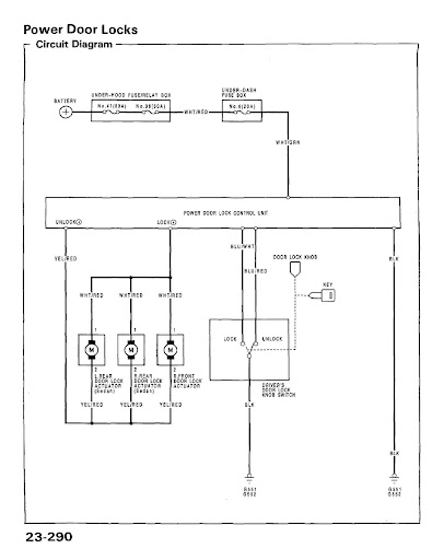
Here's what you're after. Power locks diagram for a 5G Civic with no lock switch and no OEM JDM remote locks. Unfortunately, you're faced with the problem that there is no motorized actuator in the driver's side lock switch, meaning you'll have to mount an aftermarket actuator attached to the lock rod to "powerize" the driver's side lock.
Click it to download a higher resolution image.

Click it to download a higher resolution image.
Thread Starter
Honda-Tech Member
Joined: Feb 2004
Posts: 282
Likes: 0
From: Tulsa, OK, USA
Here's what you're after. Power locks diagram for a 5G Civic with no lock switch and no OEM JDM remote locks. Unfortunately, you're faced with the problem that there is no motorized actuator in the driver's side lock switch, meaning you'll have to mount an aftermarket actuator attached to the lock rod to "powerize" the driver's side lock.
Click it to download a higher resolution image.
Click it to download a higher resolution image.
Thanks! Thats what I was wanting to confirm what I was thinking and could figure out. Looking at the us diagram and looking at the wires in the door that is what I was thinking. I will need to get a us lock module for the lock switch input and wire an aftermarket actuator to the lock output on the module.
Thanks! Thats what I was wanting to confirm what I was thinking and could figure out. Looking at the us diagram and looking at the wires in the door that is what I was thinking. I will need to get a us lock module for the lock switch input and wire an aftermarket actuator to the lock output on the module.
The door lock modules (ie., relays) on a CDM/USDM and JDM vehicle is the same, they are only wired differently to accommodate the switch.
Trending Topics
Thread Starter
Honda-Tech Member
Joined: Feb 2004
Posts: 282
Likes: 0
From: Tulsa, OK, USA
I originally wired my alarm to where the lock/unlock inputs into the control unit as if it was a usdm unit and that didn't lock any doors. On the car the passenger side will not lock unless you lock the drivers side manually and then pull the handle. Then sends the signal to lock the door. I think if I wire the alarm to the jdm blu/wht(Lock from the **** switch) and blue/red (unlock from the **** switch) and wire in the aftermarket actuator to the same as the passenger side. it looks as if the drivers door lock **** works as if you touch a switch on the door but is controlled by manually locking the door.
Question: What happens when you use your key from the outside driver's side to lock or unlock the door, when the door is shut? Both the driver and passenger side lock or unlock, correct?
Thread Starter
Honda-Tech Member
Joined: Feb 2004
Posts: 282
Likes: 0
From: Tulsa, OK, USA
I don't know. I am using 4dr civic rear handles without key hole. I would assume that you would have to close the door. lock with the key and then pull handle to lock passenger side. When you unlock the drivers side it would unlock passenger. But I don't know for sure since I don't have keyholes.
I will experiment with the above thought tonight when I get home. If it works I will do a complete write up on what I had to do.
I will experiment with the above thought tonight when I get home. If it works I will do a complete write up on what I had to do.
Thread Starter
Honda-Tech Member
Joined: Feb 2004
Posts: 282
Likes: 0
From: Tulsa, OK, USA
Here is the break down of the pins:
USDM
1. Lock input (from drivers door switch on the latch)
2.
3. Unlock Output
4. Ground
5. Lock Output
6. Lock input (from door lock switch/where you would install alarm)
7.
8. Unlock input (from door lock switch/where you would install alarm)
9.
10.
11.
12. Power coming in
JDM
1.
2.
3. Unlock Output
4. Ground
5. Lock Output
6.
7. Unlock Input (from drivers **** switch/the thing that looks like an act.)
8.
9. Lock Input (from drivers **** switch/the thing that looks like an act.)
10.
11.
12. Power Input
Here is what I did to wire the alarm. I disconnected the drivers door lock switch on the latch. I unpinned the drivers door lock switch from the connector and wired the alarm in those places. I am putting an aftermarket actuator on the drivers side and wire to pin #3 and #5. I am actually looking for a USDM passenger actuator to install instead of the aftermarket one. I like OEM better than aftermarket. I will use the aftermarket if needed since I have it from a previous car.
1.
2.
3. Unlock Output (yel/red)
4. Ground (blk)
5. Lock Output (wht/red)
6.
7. Unlock Input (from alarm output) (blue from alarm)
8.
9. Lock Input (from alarm output) (green from alarm)
10.
11.
12. Power Input (wht/grn)
Last edited by 90dteg; Jun 11, 2009 at 10:32 AM. Reason: color up date

Thread
Thread Starter
Forum
Replies
Last Post
DrewMD
Honda Civic / Del Sol (1992 - 2000)
4
Feb 5, 2017 12:29 PM
truevietluv636
Honda Civic / Del Sol (1992 - 2000)
2
Dec 5, 2007 06:13 AM