

DIY: Installing Pro Sport Premium Oil Pressure And Temp Gauges

Thread Starter
Honda-Tech Member
Joined: Jul 2001
Posts: 2,675
Likes: 1
From: Paradise, Newfoundland Canada
Alright, here is my how to of installing Pro Sport Premium Oil Pressure and Temp Gauges.
This was done in my 93 Integra but I'm sure it could be easily adapted to any Honda/Acura.
First and foremost is to gather your required parts and tools.
Parts:
The gauges themselves (I bought them from Prosportgauges.com)
Oil Filter Block Adapter (So many different brands out there, just pick one)
Tools/Consumables:
Wire cutters
#2 Phillips screw driver
Flat head screw driver
Soldering Iron
Solder
Heat Shrink Tubing
Heat Gun or lighter
Ring Terminals
Female Spade Terminals
20ga wire (Different colors. Red for power, I used white and black for ground)
Fuse holder
15A fuse
Zip Ties
Teflon Tape
Crimpers
Jack
Jack Stands
Drain Pan

Start by taking apart your dash: http://www.g2ic.com/forums/showthread.php?t=188011
Now it's time to decide where to put your gauges, this is up to you. Lots of places so get creative. I decided I wanted to put my in the center vent location as I don't really like pillar pods.
Now I will say this a few time, I did a VERY HORRIBLE job on cutting my center vents out and making a gauge panel. I rushed it and of course because of that it came out like ****. I have another bezel and I will be redoing it much nicer.
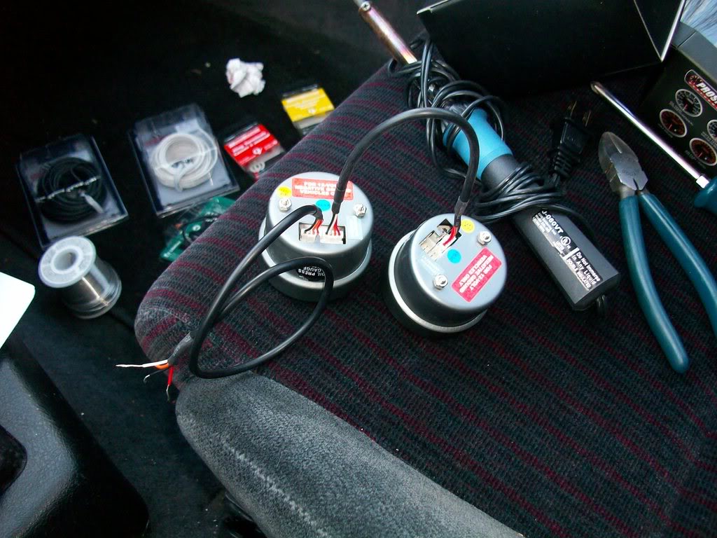
Here's the gauges ready to go:

This was done in my 93 Integra but I'm sure it could be easily adapted to any Honda/Acura.
First and foremost is to gather your required parts and tools.
Parts:
The gauges themselves (I bought them from Prosportgauges.com)
Oil Filter Block Adapter (So many different brands out there, just pick one)
Tools/Consumables:
Wire cutters
#2 Phillips screw driver
Flat head screw driver
Soldering Iron
Solder
Heat Shrink Tubing
Heat Gun or lighter
Ring Terminals
Female Spade Terminals
20ga wire (Different colors. Red for power, I used white and black for ground)
Fuse holder
15A fuse
Zip Ties
Teflon Tape
Crimpers
Jack
Jack Stands
Drain Pan
Start by taking apart your dash: http://www.g2ic.com/forums/showthread.php?t=188011
Now it's time to decide where to put your gauges, this is up to you. Lots of places so get creative. I decided I wanted to put my in the center vent location as I don't really like pillar pods.
Now I will say this a few time, I did a VERY HORRIBLE job on cutting my center vents out and making a gauge panel. I rushed it and of course because of that it came out like ****. I have another bezel and I will be redoing it much nicer.
Here's the gauges ready to go:
Thread Starter
Honda-Tech Member
Joined: Jul 2001
Posts: 2,675
Likes: 1
From: Paradise, Newfoundland Canada
First thing I'm going to do is hook up the power, ground and illumination.
Now the nice thing about the Pro Sports is there are several different colors. White is usually the main color with a switched input that when hooked up changes to the other color. I chose white/amber so it will match with my S2000 cluster (when I get the bloody thing in).
Now depending on how you wire the gauge it will light up differently. Here's the different options on wiring it.
To have them white all the time, connect only the white wire, leave the amber wire disconnected.
To have them amber all the time, connect only the amber/orange wire, leave the white wire disconnected.
To have the white during the day and amber when your parking lights on, connect the white wire to accessory and the amber wire to a switched source that comes on with the parking lights.
To have amber during the day and white at night, connect the amber wire to accessory and the white wire to a switched source that some on with the parking lights.
I chose white during the day because it's easier to read I find. At night or with the parking lights on, the gauges light up amber.
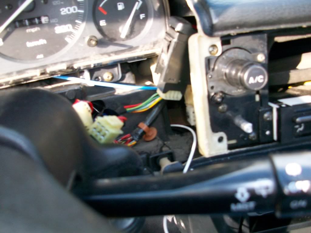
Now, where to wire them up to you ask? This little diagram shows were to hook up to on a 90-93 Integra. This is the upper part of the fuse box, located on the driver's side in the foot well. Simply solder or crimp a female spade terminal on to your wire and plug it in.

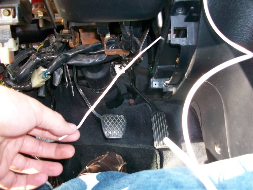
Now it's time to run the wires. I ran them down under the dash from where the HVAC vents are to where they were being connected. Run lots of slack, better to have too much wire then too little.

Now it's time to solder on the female spade connectors. If you don't know how to solder then now is a good time to learn. Crimps work fine but solder is so much better.
Strip the wire back:

Now sorry but I have no pictures of the soldering process as I need both hands to do it and I had no helper. Place some heat shrink on the wire and slide it out of the way, then put your terminal on and solder it in place. Slide the heat shrink up into place and use either a heat gun (best way) or lighter to shrink the tube. Be careful with the lighter then you don't burn/melt the wire.


That's the power side done. Next is the ground.
Now the nice thing about the Pro Sports is there are several different colors. White is usually the main color with a switched input that when hooked up changes to the other color. I chose white/amber so it will match with my S2000 cluster (when I get the bloody thing in).
Now depending on how you wire the gauge it will light up differently. Here's the different options on wiring it.
To have them white all the time, connect only the white wire, leave the amber wire disconnected.
To have them amber all the time, connect only the amber/orange wire, leave the white wire disconnected.
To have the white during the day and amber when your parking lights on, connect the white wire to accessory and the amber wire to a switched source that comes on with the parking lights.
To have amber during the day and white at night, connect the amber wire to accessory and the white wire to a switched source that some on with the parking lights.
I chose white during the day because it's easier to read I find. At night or with the parking lights on, the gauges light up amber.
Now, where to wire them up to you ask? This little diagram shows were to hook up to on a 90-93 Integra. This is the upper part of the fuse box, located on the driver's side in the foot well. Simply solder or crimp a female spade terminal on to your wire and plug it in.
Now it's time to run the wires. I ran them down under the dash from where the HVAC vents are to where they were being connected. Run lots of slack, better to have too much wire then too little.
Now it's time to solder on the female spade connectors. If you don't know how to solder then now is a good time to learn. Crimps work fine but solder is so much better.
Strip the wire back:
Now sorry but I have no pictures of the soldering process as I need both hands to do it and I had no helper. Place some heat shrink on the wire and slide it out of the way, then put your terminal on and solder it in place. Slide the heat shrink up into place and use either a heat gun (best way) or lighter to shrink the tube. Be careful with the lighter then you don't burn/melt the wire.
That's the power side done. Next is the ground.
Thread Starter
Honda-Tech Member
Joined: Jul 2001
Posts: 2,675
Likes: 1
From: Paradise, Newfoundland Canada
Do the same as above to solder a ring terminal on to your ground wire.
Pick some where to ground it. I chose the under dash bracing as it's all bare metal welded to the chassis and bare metal is a ground.
I just picked this random relay mount.

Removed the bolt, put the ring terminal in place and bolted it down again.

Now to wire up to the gauges.
On the connectors provided with the gauges there are 4 colors.
Red - Power
White - White Scale lighting
Amber/Orange - Amber scale lighting
Black - Ground
I soldered all my connections again and used heat shrink. Be careful when soldering these wires as they are of a very small gauge. Too much heat and you will melt them.
Mine are hooked up as follows.
Red and white to 12V accessory.
Amber to 12V switched.
Black to ground.
This makes the gauges white during the day and amber with the parking lights on. This was covered in Post #2.

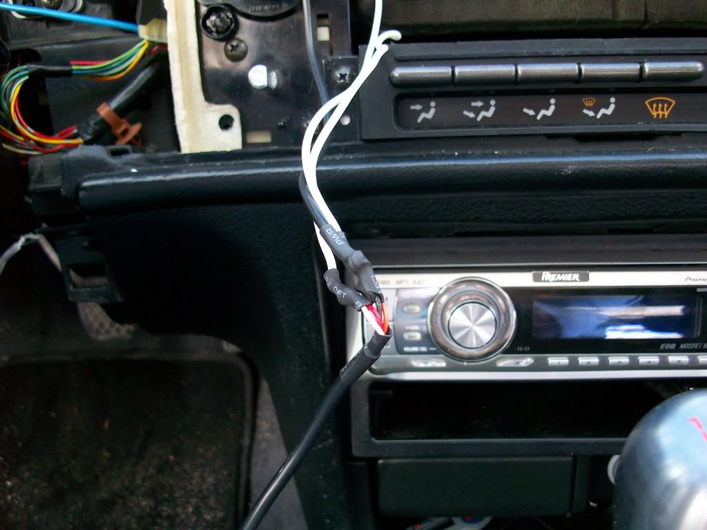
I poked the slack under the vents.

Pick some where to ground it. I chose the under dash bracing as it's all bare metal welded to the chassis and bare metal is a ground.
I just picked this random relay mount.
Removed the bolt, put the ring terminal in place and bolted it down again.
Now to wire up to the gauges.
On the connectors provided with the gauges there are 4 colors.
Red - Power
White - White Scale lighting
Amber/Orange - Amber scale lighting
Black - Ground
I soldered all my connections again and used heat shrink. Be careful when soldering these wires as they are of a very small gauge. Too much heat and you will melt them.
Mine are hooked up as follows.
Red and white to 12V accessory.
Amber to 12V switched.
Black to ground.
This makes the gauges white during the day and amber with the parking lights on. This was covered in Post #2.
I poked the slack under the vents.
Thread Starter
Honda-Tech Member
Joined: Jul 2001
Posts: 2,675
Likes: 1
From: Paradise, Newfoundland Canada
Now it's time to run the sender wires. The gauges come with senders and the wiring harness for said senders (couple meters of wire, I had lots with where I had them mounted).
First find some where to pass the wiring harness through the fire wall. I chose to chase along side the power wire for my amp.

I then pulled through the slack:

And routed the harness up to where the gauges would be:

Time to get the Blox oil filter block adapter and senders ready.
Start by wrapping a single layer of teflon tape around the senders and the 1 plug left in the adapter. Then install the 2 senders and the plug and tighten everything down. I forget what wrenches I used, sorry.
Here's the adapter and senders assembled.

DO NOT let the temp sender touch the adapter, it will give false readings.

Now it's time to get dirty.
First find some where to pass the wiring harness through the fire wall. I chose to chase along side the power wire for my amp.
I then pulled through the slack:
And routed the harness up to where the gauges would be:
Time to get the Blox oil filter block adapter and senders ready.
Start by wrapping a single layer of teflon tape around the senders and the 1 plug left in the adapter. Then install the 2 senders and the plug and tighten everything down. I forget what wrenches I used, sorry.
Here's the adapter and senders assembled.
DO NOT let the temp sender touch the adapter, it will give false readings.
Now it's time to get dirty.
Thread Starter
Honda-Tech Member
Joined: Jul 2001
Posts: 2,675
Likes: 1
From: Paradise, Newfoundland Canada
Put your e-brake on and/or block your rear wheels.
Jack the car up and secure it with jack stands, safety first!
Put a drain pan under the oil filter.
Crawl under there and remove the oil filter.

Now the adapter comes with some fittings, find one that threads into your oil filter.

There is also a seal for the adapter, lube it with some oil and place it on the adapter.
Now crawl under the car and put the adapter in place. Make sure the senders clear everything and then put the fitting on and tighten it down. Then put your oil filter back on. Make sure everything is tight.
Then plug in the senders.

Now start the car up and check for any leaks before proceeding. If you find any leaks fix them!!
After that's all done, pull the slack wire out of the way and back into the passenger compartment. Zip tie the wire out of the way both under the hood and under the dash.

Jack the car up and secure it with jack stands, safety first!
Put a drain pan under the oil filter.
Crawl under there and remove the oil filter.
Now the adapter comes with some fittings, find one that threads into your oil filter.
There is also a seal for the adapter, lube it with some oil and place it on the adapter.
Now crawl under the car and put the adapter in place. Make sure the senders clear everything and then put the fitting on and tighten it down. Then put your oil filter back on. Make sure everything is tight.
Then plug in the senders.
Now start the car up and check for any leaks before proceeding. If you find any leaks fix them!!
After that's all done, pull the slack wire out of the way and back into the passenger compartment. Zip tie the wire out of the way both under the hood and under the dash.
Thread Starter
Honda-Tech Member
Joined: Jul 2001
Posts: 2,675
Likes: 1
From: Paradise, Newfoundland Canada
Now it's time to put your dash back together.
After that's done you can plug in your gauges. The nice thing about the Pro Sport gauges is they use a daisy chain system so you only need 1 wired up and then a harness connects the next gauge.

Then plug the senders in.
NOTE: you make need to use a key or flat head screw driver to completely push the connector in.
The gauges and place and have a look!


Car turned on (sorry for the fuzzy pics):

Parking lights on:

Here's some video of the gauges.
http://www.youtube.com/watch?v=IdviENH7Euw
http://www.youtube.com/watch?v=qjanU4LZ0Og
That's it, you're done and now you can monitor your cars vitals!
After that's done you can plug in your gauges. The nice thing about the Pro Sport gauges is they use a daisy chain system so you only need 1 wired up and then a harness connects the next gauge.
Then plug the senders in.
NOTE: you make need to use a key or flat head screw driver to completely push the connector in.
The gauges and place and have a look!
Car turned on (sorry for the fuzzy pics):
Parking lights on:
Here's some video of the gauges.
http://www.youtube.com/watch?v=IdviENH7Euw
http://www.youtube.com/watch?v=qjanU4LZ0Og
That's it, you're done and now you can monitor your cars vitals!
Junior Member
Joined: Nov 2007
Posts: 67
Likes: 0
From: Dabig805, ca, usa
Pretty nice write up/diy. it temps me to do it on my car, it looks great. Oh and never remove you pix cuz im tired of searching for diy plans and finding out that the pix are gone. Once again nice write up.
Trending Topics


Thread Starter
Honda-Tech Member
Joined: Jul 2001
Posts: 2,675
Likes: 1
From: Paradise, Newfoundland Canada
I actually plan to use a piece of carbon fiber. My S2000 cluster will be done in CF so that will tie it together.
I plan to add a 3rd gauge, fuel pressure in the next little bit.
Awesome!

Thread
Thread Starter
Forum
Replies
Last Post
drivers choice
Honda Civic (2001 - 2005)
5
Nov 10, 2006 06:12 AM
CRX Lee
Road Racing / Autocross & Time Attack
60
Jul 22, 2005 09:13 PM