s2000 gauge cluster in a eg

Thread Starter
Honda-Tech Member
Joined: Dec 2007
Posts: 169
Likes: 0
From: maryland
Decided to make this little write up since http://www.dscustoms.com is down and people seem intimidated to try the conversion.
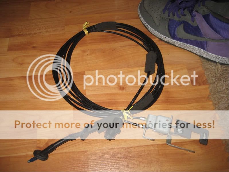
Pictures of the plugs... (pinouts are veiwed as they are in the pictures)
Ap2 cluster plug A pinout is...
1 2 3 4 5 x x x 6 7 8 9 10
11 12 13 14 15 16 x 17 18 19 20 21 22

Ap2 cluster plug B pinout is...
1 2 3 4 5 6 7 x x x 8 9 10 11 12 13 14
15 16 17 18 19 20 21 22 x 23 24 25 26 27 28 29 30

Connector A of the eg harness
10 9 8 7 6 5 4 3 2 1

Connector B of the eg harness
12 11 10 9 8 7 6 5 4 3 2 1

Connector D (not pictured)
5 4 3 2 1
D1=red/blu D2=red/blk D3=Blk D4=Red D5= Yel
Connector E (not pictured)
1 2 3 4 5
E1=Blk/yel E3=Blk E5=Blu
Ap2............................................... ................................Eg Harness
connector A
A3 WHT/RED (fuse25).......................................... .............B10 BLK/YEL
A7 RED/YEL (fuse45).......................................... ...............B10 BLK/YEL
A8 RED/BLK (circuit 11- dash and console lights(+)).............B11 RED/BLK
A9 YEL (fuse 5)................................................ ..................B10 BLK/YEL
A10 WHT/RED (fuse25).......................................... .............B10 BLK/Yel
A12 BLU/BLK (trunk indicator (-)).........................................A9 GRN
A15 RED/YEL (fuse 45)............................................... .........A1 RED/GRN
A16 RED/BLU (highbeamindicator(-)).................................. A6 BLK
A17 BLK (G501)............................................ .....................A6 BLK
A18 BLK (G501)............................................ .....................A6BLK
A19 RED (circuit 12 dash console lights(-)).......................... A6 BLK
connector B................................................. ....................EG harness
B2 BLU/YEL (cruise control (-))..D1 (I think, I'll correct it if someone lets me know)
B3 Blu (tach)............................................ B8 BLU
B4 BLU/RED (seatbelt reminder).................A10 BLU/WHT
B5 YEL/GRN (ECT Input)............................(from modifry ect converter)
B7 BLU/WHT (VSS input)............................(From dscustoms vss converter)
B10 YEL/BLK (Fuel gauge signal input)..........A7 YEL/WHT
B19 PNK (srs Indicator circuit)....................Connector E (E5 I think)
B20 ABS Indicator..............................A3 BLU/RED (I'm not sure I dont have abs)
B23 GRN/WHT (parkingbrake input).........A2 GRN/RED
B26WHT/BLU (charging system indicator)........B5 WHT/BLU
B27 YEL/RED (Engine oil pressure)..................B6 YEL/RED
B28 GRN/ORN (malfunction indicator)...............A5 GRN/ORN
B29 GRN/RED (Left turn signal indicator)...........B4 GRN/BLU
B30 GRN/YEL (Right turn signal indicator)..........B3 GRN/YEL
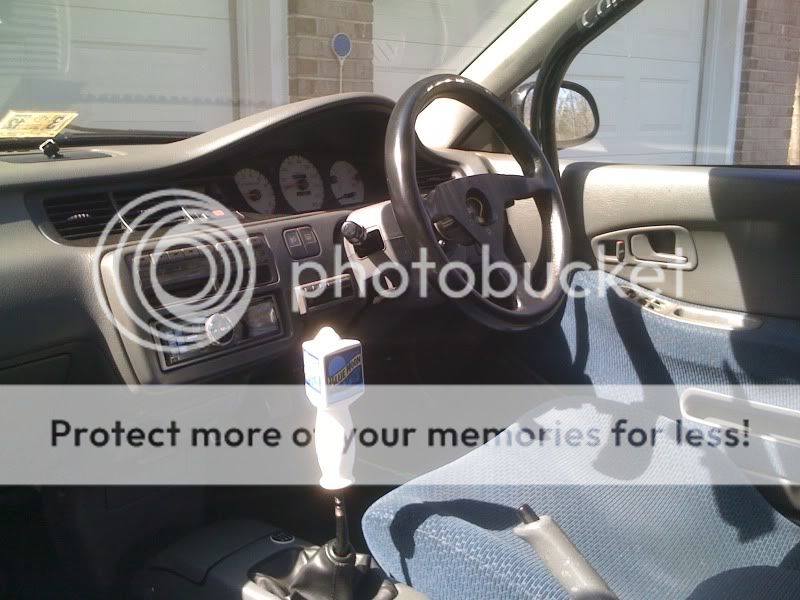
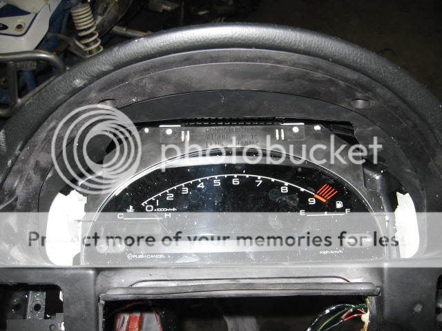
Heres a picture of it in my Coupe...


I'll add more pictures of mounting, vss, and ect stuff later.
Hope this helps some of you!

Modified by turkeyslow at 2:40 PM 8/24/2008
Pictures of the plugs... (pinouts are veiwed as they are in the pictures)
Ap2 cluster plug A pinout is...
1 2 3 4 5 x x x 6 7 8 9 10
11 12 13 14 15 16 x 17 18 19 20 21 22
Ap2 cluster plug B pinout is...
1 2 3 4 5 6 7 x x x 8 9 10 11 12 13 14
15 16 17 18 19 20 21 22 x 23 24 25 26 27 28 29 30
Connector A of the eg harness
10 9 8 7 6 5 4 3 2 1
Connector B of the eg harness
12 11 10 9 8 7 6 5 4 3 2 1
Connector D (not pictured)
5 4 3 2 1
D1=red/blu D2=red/blk D3=Blk D4=Red D5= Yel
Connector E (not pictured)
1 2 3 4 5
E1=Blk/yel E3=Blk E5=Blu
Ap2............................................... ................................Eg Harness
connector A
A3 WHT/RED (fuse25).......................................... .............B10 BLK/YEL
A7 RED/YEL (fuse45).......................................... ...............B10 BLK/YEL
A8 RED/BLK (circuit 11- dash and console lights(+)).............B11 RED/BLK
A9 YEL (fuse 5)................................................ ..................B10 BLK/YEL
A10 WHT/RED (fuse25).......................................... .............B10 BLK/Yel
A12 BLU/BLK (trunk indicator (-)).........................................A9 GRN
A15 RED/YEL (fuse 45)............................................... .........A1 RED/GRN
A16 RED/BLU (highbeamindicator(-)).................................. A6 BLK
A17 BLK (G501)............................................ .....................A6 BLK
A18 BLK (G501)............................................ .....................A6BLK
A19 RED (circuit 12 dash console lights(-)).......................... A6 BLK
connector B................................................. ....................EG harness
B2 BLU/YEL (cruise control (-))..D1 (I think, I'll correct it if someone lets me know)
B3 Blu (tach)............................................ B8 BLU
B4 BLU/RED (seatbelt reminder).................A10 BLU/WHT
B5 YEL/GRN (ECT Input)............................(from modifry ect converter)
B7 BLU/WHT (VSS input)............................(From dscustoms vss converter)
B10 YEL/BLK (Fuel gauge signal input)..........A7 YEL/WHT
B19 PNK (srs Indicator circuit)....................Connector E (E5 I think)
B20 ABS Indicator..............................A3 BLU/RED (I'm not sure I dont have abs)
B23 GRN/WHT (parkingbrake input).........A2 GRN/RED
B26WHT/BLU (charging system indicator)........B5 WHT/BLU
B27 YEL/RED (Engine oil pressure)..................B6 YEL/RED
B28 GRN/ORN (malfunction indicator)...............A5 GRN/ORN
B29 GRN/RED (Left turn signal indicator)...........B4 GRN/BLU
B30 GRN/YEL (Right turn signal indicator)..........B3 GRN/YEL
Heres a picture of it in my Coupe...
I'll add more pictures of mounting, vss, and ect stuff later.
Hope this helps some of you!
Modified by turkeyslow at 2:40 PM 8/24/2008
Thread Starter
Honda-Tech Member
Joined: Dec 2007
Posts: 169
Likes: 0
From: maryland
Thanks friends!
Okay so time to deal with the Vehicle Speed Sensor
Installing this is extremely easy!
The converter itself is a little black box probably a hair bigger then 2x2x1 and has 4 wires coming out of 1 side. Inside this little black box is 4 little dials so you can do all the compensating for wheel size and set it up how you'd like. I personally got tired of playing with it and just got it close enough before I tucked it behind the gauge cluster.
When looking at the box with the cover off and the wires hanging out the bottom my settings were....
4 5
0 1
And that was with stock honda wheels (15"si), it will be different if you have 22"s.
If anyone has theirs set up and wouldnt mind posting their settings the info would be greatly appreciated!
Wiring is extremely easy...
Orange: (Signal in) Connect this to B2 YEL/BLU on your EG harness
Red: (Power in) Connect this to B10 BLK/YEL (ignition power from eg harness)
Black Ground) Connect this to A6 BLK (ground through eg harness)
WhiteSignal out) Connect this to B7 BLU/WHT connector B of the s2000 cluster
I'll post a picture or two of the converter a little later today or tomarrow along with mounting the cluster.
Okay so time to deal with the Vehicle Speed Sensor
Installing this is extremely easy!
The converter itself is a little black box probably a hair bigger then 2x2x1 and has 4 wires coming out of 1 side. Inside this little black box is 4 little dials so you can do all the compensating for wheel size and set it up how you'd like. I personally got tired of playing with it and just got it close enough before I tucked it behind the gauge cluster.
When looking at the box with the cover off and the wires hanging out the bottom my settings were....
4 5
0 1
And that was with stock honda wheels (15"si), it will be different if you have 22"s.
If anyone has theirs set up and wouldnt mind posting their settings the info would be greatly appreciated!
Wiring is extremely easy...
Orange: (Signal in) Connect this to B2 YEL/BLU on your EG harness
Red: (Power in) Connect this to B10 BLK/YEL (ignition power from eg harness)
Black
Ground) Connect this to A6 BLK (ground through eg harness)White
Signal out) Connect this to B7 BLU/WHT connector B of the s2000 clusterI'll post a picture or two of the converter a little later today or tomarrow along with mounting the cluster.
Trending Topics
Junior Member
Joined: Jun 2007
Posts: 129
Likes: 0
From: Cape Coral, Fl, u.s.
not to b dumb, i was reading up on this, and i thought there was problems with the sensors, since the s2k has digital readings, i dunno, don't flame me, im just wondering because i have a spare s2k cluster 
Thread Starter
Honda-Tech Member
Joined: Dec 2007
Posts: 169
Likes: 0
From: maryland
Yeah sorry I havn't finished the write up, no one seemed terribly interested, but anyway...
for the temp sensor...
get them at... http://www.modifry.com
the wiring diagram is here... http://www.modifry.com/product...m.pdf
Please keep in mind that wiring diagram is with a S2000 ecu so the 2 wires you need may be on different plugs
You only need to hook up 4 of the wires...
White: Gets spliced into the wire that goes from your stock ECT sensor to your ecu, I forgot the color of the wire and which plug it goes on (I'll look it up later)
Green: You need to solder a wire to this and run it to the back of your cluster into B5 Yel/Grn
Yellow: Connect this to a 5v power supply to your ecu, (I'll look up where this is later)
Black: Ground, I did it the lazy way and just wrapped it around a bolt behind the ecu
You can also connect the converter behind the cluster just connect the white wire to your coolant temp. sending unit(I'll look up which plug position its in later) and run a wire from the converter to a 5volt power scource at the ecu.
I'm not sure whats going on with dscustoms.com and his speed sensor, The speed sensor converters on modifry.com ARE NOT FOR A CIVIC
I'm going to try and update this post tomarrow so all this info is more useful then it is now
Joined: Aug 2008
Posts: 51
Likes: 0
From: Oro Valley, AZ, 85755
Nah its fine, worst comes to worst if its not fully explained im sure i can piece the rest together on my own...but appreciate the add-ons...One question, does it work well as far as accuracy with the different gauge readings???...


Honda-Tech Member
Joined: Jun 2006
Posts: 728
Likes: 0
From: NEWBURGH, NY, ORANGE
i understand that this is for the s2k in a eg but heres mine in my 90 cb accord.
its all wired up besides the speedhealer and the modifry for the water temp. just need to get some more carbon fiber for the edges. any info where i can get a sheet?
its all wired up besides the speedhealer and the modifry for the water temp. just need to get some more carbon fiber for the edges. any info where i can get a sheet?
Honda-Tech Member
Joined: Nov 2001
Posts: 8,651
Likes: 3
From: Dallas, Tejas
Those all look terrible. Sorry to be honest, apparently nobody else will be.
Now if you guys take the time to mold the gauge bezels to contour with the S2k cluster, THEN it would be really cool.
Otherwise they just look pretty silly in my opinion.
Now if you guys take the time to mold the gauge bezels to contour with the S2k cluster, THEN it would be really cool.
Otherwise they just look pretty silly in my opinion.
Thread Starter
Honda-Tech Member
Joined: Dec 2007
Posts: 169
Likes: 0
From: maryland
this post will give you some links for carbon fiber products...
https://honda-tech.com/zerothread/2367798
Jonathan: I agree, mine doesn't look professional at all, however my car wasn't to showcase my work as much as it was simply to try something new that you didn't see at car shows at the time. However if you check out Oneoffaccords build thread you'd see that he is really putting tons of work and emphasis on detail I trust him to make his look better then mine did.
Hope this post is helping!
Honda-Tech Member
Joined: Nov 2001
Posts: 8,651
Likes: 3
From: Dallas, Tejas
<TABLE WIDTH="90%" CELLSPACING=0 CELLPADDING=0 ALIGN=CENTER><TR><TD>Quote, originally posted by turkeyslow »</TD></TR><TR><TD CLASS="quote">this post will give you some links for carbon fiber products...
https://honda-tech.com/zerothread/2367798
Jonathan: I agree, mine doesn't look professional at all, however my car wasn't to showcase my work as much as it was simply to try something new that you didn't see at car shows at the time. However if you check out Oneoffaccords build thread you'd see that he is really putting tons of work and emphasis on detail I trust him to make his look better then mine did.
Hope this post is helping!</TD></TR></TABLE>
I would love to see a "finished" version of this cluster setup!!!
Honda-Tech Member
Joined: Jun 2006
Posts: 728
Likes: 0
From: NEWBURGH, NY, ORANGE
ive been so busy doing other side work or going away for personal reasons that i have finished the cluster or the car itself. im leaning towards dry or wet carbon fiber.