

Technical drafters some help here Accurately copying contours radius help.

Thread Starter
Honda-Tech Member
Joined: Aug 2004
Posts: 4,638
Likes: 0
From: Altamonte Springs/Orlando, Florida, USA
I'm on the journey to learning technical drafting to do personal projects I've been off/on with it but now I'm seriously motivated and I need some help.
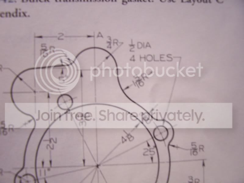
How do you figure the radius on the outer perimeter of parts to properly draw the contours like this here's an example in my book :
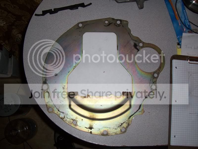
My part .
How do you figure the radius on the outer perimeter of parts to properly draw the contours like this here's an example in my book :
My part .
Joined: May 2002
Posts: 3
Likes: 1
From: banned NC
like how would you measure it or what?
Id start with all the holes that I could measure first.
best way would be to get someone to use a CMM for you though.
Id start with all the holes that I could measure first.
best way would be to get someone to use a CMM for you though.
Honda-Tech Member
Joined: Jul 2002
Posts: 812
Likes: 0
From: Peg City, 204
I don't know what program you're using, (but if it was Autocad) I would figure out all the easy (yet important) inside dimensions such as the holes and draft them normally. Then I would manually trace the whole part onto paper, scan it, paste it into autocad and line it up (and scale as needed) as best I could on top of the holes that you drafted. Then send that pic to the back (ie make it like the bottom layer) draw circles and arcs on top of that pic on a diff layer until you figure out a radius that lines up nicely, trim, etc... delete the scanned pic you pasted... done.
That's how I would do it. Everyone drafts differently, and I'm trained in civil, not mech so a mech guy would probably do it more efficiently than me. (i hope)
That's how I would do it. Everyone drafts differently, and I'm trained in civil, not mech so a mech guy would probably do it more efficiently than me. (i hope)
Honda-Tech Member
Joined: Apr 2005
Posts: 1,895
Likes: 0
From: Lincoln, Ne, USA
you can buy (or make) circles with different radii and hold them next to the curve you want to know
Honda-Tech Member
Joined: Dec 2000
Posts: 20,006
Likes: 3
From: Tampa, FL
Radius gages, circles, scale, etc. The idea about tracing and importing into ACAD works pretty good for not so technical pieces. We have had to do this many times with aircraft parts as they never match the drawings after 30 years
Thread Starter
Honda-Tech Member
Joined: Aug 2004
Posts: 4,638
Likes: 0
From: Altamonte Springs/Orlando, Florida, USA
<TABLE WIDTH="90%" CELLSPACING=0 CELLPADDING=0 ALIGN=CENTER><TR><TD>Quote, originally posted by dfoxengr »</TD></TR><TR><TD CLASS="quote">like how would you measure it or what?
Id start with all the holes that I could measure first.
best way would be to get someone to use a CMM for you though.</TD></TR></TABLE>
My question is there in the first picture where '' a '' is it says ''3/4th's '' or right under it there is another curve that says ''1-3/16th's'' how are those radius figured?
''
How do you figure the radius on the outer perimeter of parts to properly draw the contours like this here's an example in my book''
<TABLE WIDTH="90%" CELLSPACING=0 CELLPADDING=0 ALIGN=CENTER><TR><TD>Quote, originally posted by Justin Jones »</TD></TR><TR><TD CLASS="quote">I don't know what program you're using, </TD></TR></TABLE>
I'm not using a CAD program this is buy hand which is why I said technical drafters I want to learn that later .
<TABLE WIDTH="90%" CELLSPACING=0 CELLPADDING=0 ALIGN=CENTER><TR><TD>Quote, originally posted by Blown90hatcH »</TD></TR><TR><TD CLASS="quote">Radius gages, circles, scale, etc. The idea about tracing and importing into ACAD works pretty good for not so technical pieces. We have had to do this many times with aircraft parts as they never match the drawings after 30 years</TD></TR></TABLE>
Radius gauges?
Honda-Tech Member
Joined: Nov 2004
Posts: 1,309
Likes: 0
From: Miura-Shi, Japan
radius templates. Or if it doesn't need to be exact, you can use a set of french curves to copy it over.

Trending Topics
Member
Joined: Jan 2003
Posts: 2,933
Likes: 1
From: northern, ma, US
<TABLE WIDTH="90%" CELLSPACING=0 CELLPADDING=0 ALIGN=CENTER><TR><TD>Quote, originally posted by narfdanarf »</TD></TR><TR><TD CLASS="quote">radius templates. Or if it doesn't need to be exact, you can use a set of french curves to copy it over.
</TD></TR></TABLE>
those are nice...but i always used a scale & compass in my drafting class...because our prof wanted perfection....needless to say those 5hr drawings are now worth crap to me as im a civil and they love acad
</TD></TR></TABLE>those are nice...but i always used a scale & compass in my drafting class...because our prof wanted perfection....needless to say those 5hr drawings are now worth crap to me as im a civil and they love acad
Joined: May 2002
Posts: 3
Likes: 1
From: banned NC
<TABLE WIDTH="90%" CELLSPACING=0 CELLPADDING=0 ALIGN=CENTER><TR><TD>Quote, originally posted by MidShipCivic »</TD></TR><TR><TD CLASS="quote">Radius gauges? </TD></TR></TABLE>
google?
lol
google?
lol
Thread Starter
Honda-Tech Member
Joined: Aug 2004
Posts: 4,638
Likes: 0
From: Altamonte Springs/Orlando, Florida, USA
<TABLE WIDTH="90%" CELLSPACING=0 CELLPADDING=0 ALIGN=CENTER><TR><TD>Quote, originally posted by dfoxengr »</TD></TR><TR><TD CLASS="quote">
google?
lol</TD></TR></TABLE>
That still doesn't help, it shows me a radius as it appears to have an imaginary circle there but it doesnt how do I figure that out? I don't have a straigth anwser anywhere hell I could trace it and get exact contours...
Modified by MidShipCivic at 6:22 PM 8/10/2008
google?
lol</TD></TR></TABLE>
That still doesn't help, it shows me a radius as it appears to have an imaginary circle there but it doesnt how do I figure that out? I don't have a straigth anwser anywhere hell I could trace it and get exact contours...
Modified by MidShipCivic at 6:22 PM 8/10/2008
Thread Starter
Honda-Tech Member
Joined: Aug 2004
Posts: 4,638
Likes: 0
From: Altamonte Springs/Orlando, Florida, USA
<TABLE WIDTH="90%" CELLSPACING=0 CELLPADDING=0 ALIGN=CENTER><TR><TD>Quote, originally posted by dfoxengr »</TD></TR><TR><TD CLASS="quote">no, google for the radius gauges.</TD></TR></TABLE>
Then you don't know?
There is a way to do it with out them.
Then you don't know?
There is a way to do it with out them.
Honda-Tech Member
Joined: Dec 2000
Posts: 20,006
Likes: 3
From: Tampa, FL
I take it that part you have is what you want to measure? Sounds like you are just getting started with drafting, so tracing is probably going to be your best starting point. Trace what ever you can. Get some radius gages and measure the radii of all the things you can. Once you know the size, draw the circles to find your centers. Leave it rough sketched for now with all the cirles....you can erase them later. That should get you started.
Joined: May 2002
Posts: 3
Likes: 1
From: banned NC
im not sure if i understand what you meant by that, but yes I know what they are, and have some.
if you were accurate you could draw 2 tangent lines along the circumference, then perpendicular lines to those, and where they intersect is the circle center, then you can measure from there for the radius.
if you were accurate you could draw 2 tangent lines along the circumference, then perpendicular lines to those, and where they intersect is the circle center, then you can measure from there for the radius.
Thread Starter
Honda-Tech Member
Joined: Aug 2004
Posts: 4,638
Likes: 0
From: Altamonte Springs/Orlando, Florida, USA
<TABLE WIDTH="90%" CELLSPACING=0 CELLPADDING=0 ALIGN=CENTER><TR><TD>Quote, originally posted by Blown90hatcH »</TD></TR><TR><TD CLASS="quote">I take it that part you have is what you want to measure? Sounds like you are just getting started with drafting, </TD></TR></TABLE>
Yes.
<TABLE WIDTH="90%" CELLSPACING=0 CELLPADDING=0 ALIGN=CENTER><TR><TD>Quote »</TD></TR><TR><TD CLASS="quote">
so tracing is probably going to be your best starting point. Trace what ever you can. Get some radius gages and measure the radii of all the things you can. Once you know the size, draw the circles to find your centers. Leave it rough sketched for now with all the cirles....you can erase them later. That should get you started.</TD></TR></TABLE>
Free hand sketching.
Yeah I'm trying to ask to get another persons word it's hard when someone who does it all the time just scrapes the surface and tells me just go grab some gauges. I want to know the shear BASE of the technique.
There is an example in my book but they don't give me formulas.
This was what I'm trying to go over because this Skyline GTR trans shield has inconsistent round sections that taper at the ends.
The example looks like this.

Calculating a curves radius
http://www.woodworking.com/art...=1835
Yes.
<TABLE WIDTH="90%" CELLSPACING=0 CELLPADDING=0 ALIGN=CENTER><TR><TD>Quote »</TD></TR><TR><TD CLASS="quote">
so tracing is probably going to be your best starting point. Trace what ever you can. Get some radius gages and measure the radii of all the things you can. Once you know the size, draw the circles to find your centers. Leave it rough sketched for now with all the cirles....you can erase them later. That should get you started.</TD></TR></TABLE>
Free hand sketching.
Yeah I'm trying to ask to get another persons word it's hard when someone who does it all the time just scrapes the surface and tells me just go grab some gauges. I want to know the shear BASE of the technique.
There is an example in my book but they don't give me formulas.
This was what I'm trying to go over because this Skyline GTR trans shield has inconsistent round sections that taper at the ends.
The example looks like this.
Calculating a curves radius
http://www.woodworking.com/art...=1835

Honda-Tech Member
Joined: Feb 2004
Posts: 371
Likes: 0
From: Cream Ridge, NJ
That shield is a complex part to start with for not having a clue.
Most of the small radius (part circles) can be turned into circles. You have no tangent dimensions shown in the original drawing just circle center points. Get the radius templates for the smaller circles as they will have a center point included unlike the larger radius templates. By the way the math your looking for is covered in a geometry book and not a drafting one. If you are thinking of having a part water or laser cut your drawing will have to be converted into a cad file to be imported into a machine accurately. Do yourself a favor and learn a cad program. You won't need to do any math for calculating tangent points or circle centerlines. Look up a drafting supplier ( very few good ones still exsist) and look at the available patterns and templates. Just remember that everything on a drawing is nothing more then the relationship of one point to another. Knowing the centerpoint and radius of 2 circles or arcs you can calculate the center point of a tangent 3rd as long as you know it's radius. Just remember the math is Geometry and not drafting.
Most of the small radius (part circles) can be turned into circles. You have no tangent dimensions shown in the original drawing just circle center points. Get the radius templates for the smaller circles as they will have a center point included unlike the larger radius templates. By the way the math your looking for is covered in a geometry book and not a drafting one. If you are thinking of having a part water or laser cut your drawing will have to be converted into a cad file to be imported into a machine accurately. Do yourself a favor and learn a cad program. You won't need to do any math for calculating tangent points or circle centerlines. Look up a drafting supplier ( very few good ones still exsist) and look at the available patterns and templates. Just remember that everything on a drawing is nothing more then the relationship of one point to another. Knowing the centerpoint and radius of 2 circles or arcs you can calculate the center point of a tangent 3rd as long as you know it's radius. Just remember the math is Geometry and not drafting.
Honda-Tech Member

Joined: Nov 2003
Posts: 5,986
Likes: 2
From: Kitchener, Ontario, CANADA
<TABLE WIDTH="90%" CELLSPACING=0 CELLPADDING=0 ALIGN=CENTER><TR><TD>Quote, originally posted by KFMRC »</TD></TR><TR><TD CLASS="quote">Do yourself a favor and learn a cad program.</TD></TR></TABLE>
Thread Starter
Honda-Tech Member
Joined: Aug 2004
Posts: 4,638
Likes: 0
From: Altamonte Springs/Orlando, Florida, USA
<TABLE WIDTH="90%" CELLSPACING=0 CELLPADDING=0 ALIGN=CENTER><TR><TD>Quote, originally posted by KFMRC »</TD></TR><TR><TD CLASS="quote">That shield is a complex part to start with for not having a clue. </TD></TR></TABLE>
And you can't say the same about cad?
And you can't say the same about cad?
Honda-Tech Member
Joined: Nov 2003
Posts: 5,986
Likes: 2
From: Kitchener, Ontario, CANADA
I dont know about 'cake'.. this part is quite complex. Way over the head of someone who is just starting off.
<TABLE WIDTH="90%" CELLSPACING=0 CELLPADDING=0 ALIGN=CENTER><TR><TD>Quote, originally posted by dfoxengr »</TD></TR><TR><TD CLASS="quote">best way would be to get someone to use a CMM for you though.</TD></TR></TABLE>
<TABLE WIDTH="90%" CELLSPACING=0 CELLPADDING=0 ALIGN=CENTER><TR><TD>Quote, originally posted by dfoxengr »</TD></TR><TR><TD CLASS="quote">best way would be to get someone to use a CMM for you though.</TD></TR></TABLE>
Honda-Tech Member
Joined: Feb 2004
Posts: 371
Likes: 0
From: Cream Ridge, NJ
learned drafting in HS and passed my college test for it which eliminated the need of making more worthless drawings. I say to learn a cad rogram because once you do you will find it much easier to do everything. I use a program made by Ashlar. The cad version called graphite. I also have the solid package cobalt. Graphite is what I use for 99% of the work that needs to be done. It is not a cheap program but is very easy to use. Much easier and faster then Auto cad. I started using it in 95 as a version called "Drawingboard". That version cost me $135 dollars back then and I still use it today for the drawings that were created with it. It was the ashlar version of auto cad lite. Drawingboard was a simple 2d version of graphite. They look identical except for a few extra options in the pull down menu.
I do everything in the program. Need a bracket I draw it up faster then anyone can lay it out on a pc of metal. If you need multiples you just drag over as many as you want. YOU PRINT IT OUT AND GLUE STICK IT TO THE METAL AND YOU HAVE A VERY VISIBLE LINE AND ALSO CENTER MARKS FOR HOLES AND YOU ALSO HAVE IT FOR THE NEXT TIME IF YOU SAVE IT. You can also ut multiple sheets together for the larger stuff.
Need to edit something highlight it drag it over as a copy make your changes and see if they work if not the original is still there. I have a beautiful drafting table with a Vemco vertical track machine and will never use it again. CAD is the best thing. Even the basic drawing board program had an internal accuracy of 16 decimal places from what I understand. I can do in 10 minutes what would probably take you a day or more to draw and do all the calculations for tangents and endpoints you would need for a cnc program. I have 2 cnc mills and also a cnc lathe plus enough equipment to make almost anything I want. LEARN A CAD PROGRAM
Modified by KFMRC at 1:32 PM 8/11/2008
Honda-Tech Member
Joined: Jul 2002
Posts: 812
Likes: 0
From: Peg City, 204
Even my drafting instructor in college said that the half a year we spent manually drafting was a total waste, and if he could change the way the college teaches the program, students would work in CAD from day one. There is nothing (important) you can learn from manual drafting that you can't learn from CAD.
Junior Member
Joined: Nov 2006
Posts: 588
Likes: 0