

MPFI into a 90 hatch HELP!

Thread Starter
Honda-Tech Member
Joined: Sep 2005
Posts: 583
Likes: 0
From: upstate, ny, us
I need some help with my 90 hatch, i got it without an engine but have one from a 90 ex sedan, so it has mpfi... everything i see on the forums only has info on converting stock dpfi engine harness to work with the mpfi.... my question is that since i have the mpfi harness on my motor, what other wiring do i have to do to get it to run?Any help is much appreciated... ive been searching for a while and didnt find what i needed yet... 
Thread Starter
Honda-Tech Member
Joined: Sep 2005
Posts: 583
Likes: 0
From: upstate, ny, us
ok... i got a harness on a dpfi engine... do i really have to cut wires off the ecu harness and run them into the bay? or can i do it all on the harness?
Honda-Tech Member
Joined: Mar 2006
Posts: 554
Likes: 0
From: Indiana
Trending Topics
Honda-Tech Member
Joined: Apr 2006
Posts: 462
Likes: 0
From: Walnut, CA, US
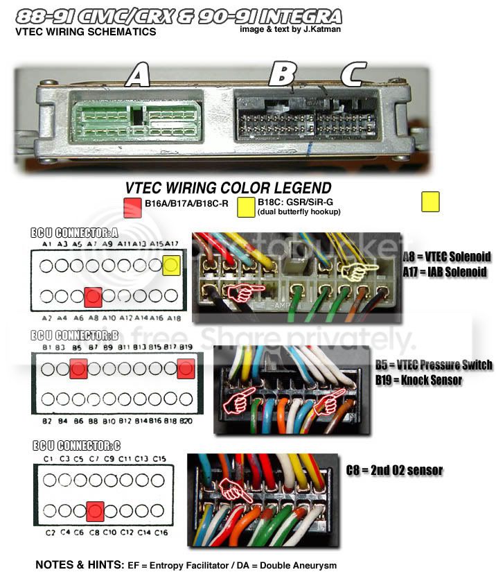
okay yes u have to do a little wire cutting. im getting ready to do mine. i have a std as well and im doing either a full ZC or stock B20 anyways u need to research a lil more. ive been doing my homework for about six months and it pays off. Thank H-T.  . here is a link for a visual conversion from DPFI-MPFI. http://www.ef-honda.com/ben/EFwiring.php ... dont worry about the Vtec wiring unless u plan for later use. make sure u get an OBD0 injector resistor box. the one off an EF Si will fit perfectly behind the driver shock tower. Also please Solder and heatshrink all ur connections and the wires u add plaese put in a wire loom and tape up. u dont want wires hanging everywhere pluss u can make it look stock. i hope this helps u out. IM if anymore questions u need answering
. here is a link for a visual conversion from DPFI-MPFI. http://www.ef-honda.com/ben/EFwiring.php ... dont worry about the Vtec wiring unless u plan for later use. make sure u get an OBD0 injector resistor box. the one off an EF Si will fit perfectly behind the driver shock tower. Also please Solder and heatshrink all ur connections and the wires u add plaese put in a wire loom and tape up. u dont want wires hanging everywhere pluss u can make it look stock. i hope this helps u out. IM if anymore questions u need answering
Thread Starter
Honda-Tech Member
Joined: Sep 2005
Posts: 583
Likes: 0
From: upstate, ny, us
Thanks for the info guys... ive done a bunch of work to newer civics and integras but never one this old... so its new to me...but so far its not too bad and this project is comming together nicely... im eventually going to put my gsr swap in it but thats down the road(when my gsr gets its new motor) 
Honda-Tech Member
Joined: Jun 2003
Posts: 1,466
Likes: 0
From: mi
Just graft your Ex/Si harness onto the STD harness just like you would on any other MPFI swap. There are quite a few good write ups on this. I believe when i did my first few MPFI's i used fourthgenhatch's website, that is, if its still around, its been awhile lol
Honda-Tech Member
Joined: Dec 2005
Posts: 1,225
Likes: 0
From: Frederick, MD
http://images.google.com/imgre...a%3DG
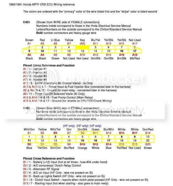
1. Pins B10 and B12 are empty.
2. Unused pins can be taken from B2 or B11 And sometimes B12
3. Cut orange and white wires off at C1 and C2 and connect them to wires added at B10 and B12. Orange-B10. White-B12.
4. Run wires from C1 and C2 on the ecu into the engine compartment. Label these wires for later use.
5. Cut wires at A3 and A7 leave excess for later use. Run these wires into the engine bay and label them to be used later on .
6. TPS and EACV plugs are too short and must be extended.
7. Switch green/white and yellow/white wires on TPS since the dx turns the opposite way.
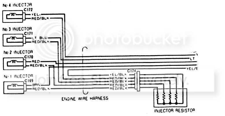
8. Connect the yellow/black wires from the two DX injector harnesses and run it to the yellow/black wire on the injector resistor box.
9. Connect the yellow wire from the DX injector to the #1 injector (brown wire). Connect the red wire from the DX injector and run it to the #3 injector (blue wire). Connect the A3 wire to the #2 injector (red wire). Connect the A7 wire to the #4 injector (yellow wire). Connect the 4 red/black wires from injector resistor box to each injector.
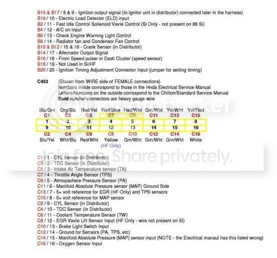
10. Connect C1 to blue/green wire on cylinder position sensor plug. Connect C2 to blue/yellow wire on cylinder position sensor plug the rest of the wires are color matched for your dx to the si wires
1. Pins B10 and B12 are empty.
2. Unused pins can be taken from B2 or B11 And sometimes B12
3. Cut orange and white wires off at C1 and C2 and connect them to wires added at B10 and B12. Orange-B10. White-B12.
4. Run wires from C1 and C2 on the ecu into the engine compartment. Label these wires for later use.
5. Cut wires at A3 and A7 leave excess for later use. Run these wires into the engine bay and label them to be used later on .
6. TPS and EACV plugs are too short and must be extended.
7. Switch green/white and yellow/white wires on TPS since the dx turns the opposite way.
8. Connect the yellow/black wires from the two DX injector harnesses and run it to the yellow/black wire on the injector resistor box.
9. Connect the yellow wire from the DX injector to the #1 injector (brown wire). Connect the red wire from the DX injector and run it to the #3 injector (blue wire). Connect the A3 wire to the #2 injector (red wire). Connect the A7 wire to the #4 injector (yellow wire). Connect the 4 red/black wires from injector resistor box to each injector.
10. Connect C1 to blue/green wire on cylinder position sensor plug. Connect C2 to blue/yellow wire on cylinder position sensor plug the rest of the wires are color matched for your dx to the si wires

Want to save yourself the headache?
I make these on a daily basis and I supply you with a detailed diagram and label
the 4 wires that you insert into the ecu plugs, Simple procedure I can also give
you technical support.
Let me know what kind of conversion you need and I can make it for you within 1-
3 days depending on my harness order status, Peace!

Thread Starter
Honda-Tech Member
Joined: Sep 2005
Posts: 583
Likes: 0
From: upstate, ny, us
Does anyone have some good pics of the plugs and stuff for the dist. and iacv sensors and such? It would be greatly appreciated. 
Thread Starter
Honda-Tech Member
Joined: Sep 2005
Posts: 583
Likes: 0
From: upstate, ny, us
Ok, i got the engine harness complete and on the engine...thanks for the help guys... but i need one more thing... The manifold has a fast idle solenoid valve and the write up didnt have anything about it.... i think i can use the wires from the tandem valve... my chiltons book says th wires pretty much go to the same place, can anyone confirm this?THe engine is a d16a6 if if t matters...

Thread
Thread Starter
Forum
Replies
Last Post
crx-si
Honda CRX / EF Civic (1988 - 1991)
1
Sep 1, 2008 05:54 PM