

NASA CAGE LEGALITY ?!

Thread Starter
Honda-Tech Member
Joined: Nov 2007
Posts: 1,312
Likes: 0
From: Lake Elsinore, CA, USA
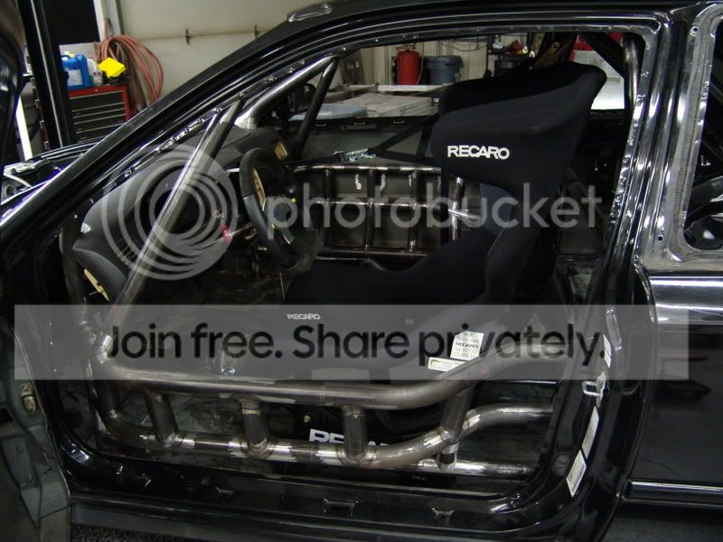
Since we are on the topic of my cage and the diagonal bar being illegal. I will add some pics of the rest of it and see what I have to fix or not before I get too far along with the build.


New User
Joined: Jun 2001
Posts: 1,224
Likes: 0
From: Roanoke, VA
You might have a problem with these:
15.6.7 Diagonal Brace
At least one (1) diagonal brace shall be used in the same plane as the main hoop. One
end of the diagonal brace shall attach to the corner, or horizontal part, of the main hoop
above the driver�s head, within twelve (12) inches of the driver�s-side corner. The other
end of the diagonal brace shall attach to the mounting plate (or to the main hoop as
close to the mounting plate as practically possible) diagonally opposed to the driver�s
head (passenger floor).
15.6.14.B Tube / Mounting Plate Specifications
Any number of tubes may attach to a plate so long as they are touching each other at
the plate. There may be a small gap between tubes to allow welding 360 degrees
around each tube. If there is no gap between the tubes, they must be welded around the base as much as possible to form a single figure-eight weld, AND the tubes must be
welded to each other two (2) inches up from the base plate.
Based on what I can see of the horizontal bar, if used to mount the shoulder belts, I might be too low to properly set up the belts.
6. The shoulder harness shall be mounted behind the driver and above a line drawn
downward from the shoulder point at an angle of no more than twenty (20)
degrees with the horizontal.
Thread Starter
Honda-Tech Member
Joined: Nov 2007
Posts: 1,312
Likes: 0
From: Lake Elsinore, CA, USA
Okay,
The harness bar is 10 deg. below, so im okay there. the diag bar is my main concern.
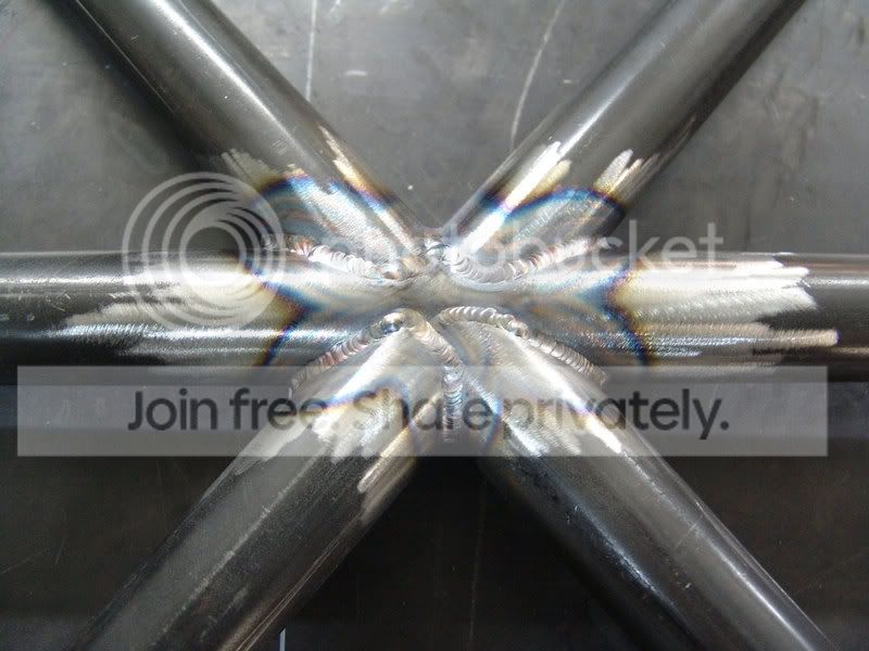
The rear diagonal bar meets at the tubes and not the plate, i see. But the tube across the bottom is weled to the base plate as to make that area solid. But that is an optional bar any way so not really relevant.
Looks like i have to cut the digonal and harness bars out and redo it. ..GRR. not easy.
The harness bar is 10 deg. below, so im okay there. the diag bar is my main concern.
The rear diagonal bar meets at the tubes and not the plate, i see. But the tube across the bottom is weled to the base plate as to make that area solid. But that is an optional bar any way so not really relevant.
Looks like i have to cut the digonal and harness bars out and redo it. ..GRR. not easy.
Honda-Tech Member
Joined: Jun 2003
Posts: 197
Likes: 0
From: Chesapeake, VA
Just for a clarification on the diagonal brace for my own peace of mind before I go weld mine in...Does that diagonal have to be one piece? Or can the Horizontal bisect the diagonal? I've been told that it's stronger this way and since the ccr isn't exactly clear on it I wanted to make sure.
Sorry not trying to jack the thread by the way, just I know Jim would know better than anybody concerning this and NASA rules.
Sorry not trying to jack the thread by the way, just I know Jim would know better than anybody concerning this and NASA rules.
Suspetise...
Joined: Nov 2002
Posts: 12,287
Likes: 1
From: Burninating the peasants yo
Yeah, that rear diagonal isn't the one being addressed in that particular rule (which specifies the diagonal in the same plane as the main hoop), so you shouldn't have a problem there. The diagonal that IS in the plane of the main hoop is attached at the plate properly as well, so if it were one piece you'd be cherry.
Meanwhile, I don't envy you that modification, having fiddled with my own cage.
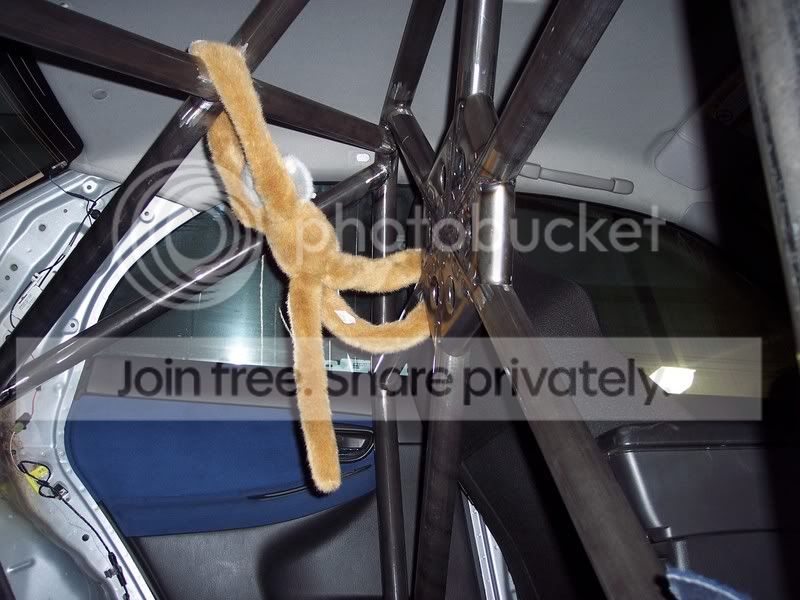
On another note, you don't have a dashbar. I don't remember if that's required or not, but it certainly is a good idea. Also, I love those doorbars. Nicely done, and nice design. Do you have any pics of the halo bar area?
Meanwhile, I don't envy you that modification, having fiddled with my own cage.
On another note, you don't have a dashbar. I don't remember if that's required or not, but it certainly is a good idea. Also, I love those doorbars. Nicely done, and nice design. Do you have any pics of the halo bar area?
Thread Starter
Honda-Tech Member
Joined: Nov 2007
Posts: 1,312
Likes: 0
From: Lake Elsinore, CA, USA
Heres the only one I have showing the upper cage area.

Here is my sponsor KIWIs car that has log books for NASA and SCCA

Modified by JW racing at 2:27 PM 1/10/2008
Modified by JW racing at 10:42 AM 1/11/2008
Here is my sponsor KIWIs car that has log books for NASA and SCCA
Modified by JW racing at 2:27 PM 1/10/2008
Modified by JW racing at 10:42 AM 1/11/2008
Trending Topics
Honda-Tech Member
Joined: Nov 2004
Posts: 1,045
Likes: 0
From: Dementia
<TABLE WIDTH="90%" CELLSPACING=0 CELLPADDING=0 ALIGN=CENTER><TR><TD>Quote, originally posted by Stinkycheezmonky »</TD></TR><TR><TD CLASS="quote">triple, what complaints did your tech guy have about your cage?</TD></TR></TABLE>
My tech shop is DiDRace which is the same people who built my cages and many others. Only funny thing that popped up was one day the regional director was hanging out at the shop, and noticed the cage. First he told us we over build cages, then he brought up the main hoops. He tried to make it sound like my setup is unsafe
just because of the 2 piece diagonal. He really didn't come up with a good enough reason safety wise to do it one way or the other. If somebody shows me proof that its safer then my current configuration, i'll consider changing it. My cars are geared more towards SCCA classes anyways, but if its going to be a hassle to run a NASA event, i'll gladly save my money and skip them.
Cages in question...
Civic (i'll get newer pics over the weekend)
and
Subaru roll bar... to be finished shortly
before gussets
So like i mentioned, i would talk with your regional people before you go and cut anything up.
Honda-Tech Member
Joined: Mar 2002
Posts: 663
Likes: 0
From: Center of Canada
<TABLE WIDTH="90%" CELLSPACING=0 CELLPADDING=0 ALIGN=CENTER><TR><TD>Quote, originally posted by Stinkycheezmonky »</TD></TR><TR><TD CLASS="quote">More pics of the Civic too  </TD></TR></TABLE>
x2
</TD></TR></TABLE>x2
Honda-Tech Member
Joined: May 2002
Posts: 13,483
Likes: 0
From: cali
Just because tech inspectors log book a car, and or don't stop you from running with some requirement and or having something illegal in no way shape or form makes it legal. It just means that person/car hasn't been caught yet.
Same thing goes for class specific modifications, just because Racer A has been racing for 6 races with an illegal flux capacitor does not mean it is legal, it simply means it hasn't been caught yet.
Grumpy (user name on many forums), has answered the question. He is pretty much the be all end all of all issues in the CCR. Grumpy's real name is Jim Politi, if you look at the bottom of the first page of the CCR there is a box, that mentions him.
Honda-Tech Member


Joined: Jan 2001
Posts: 4,749
Likes: 26
From: Portland, OR
Here is some pictures of my cage while it was being painted (i did the painting myself last weekend so i dont have any completed pictures yet)
And yes, its REALLY bright, but its a race car.


before the painting..

Thread Starter
Honda-Tech Member
Joined: Nov 2007
Posts: 1,312
Likes: 0
From: Lake Elsinore, CA, USA
I found out Chris D who got 3rd in H1 at the nats has the same diag bar setup as me. Looks to be alright .
Dash bar is going to be put in today and off to paint tuesday..
.Dash bar is going to be put in today and off to paint tuesday..
Honda-Tech Member
Joined: Aug 2003
Posts: 1,014
Likes: 0
From: 8 blocks from George Bush, DC
Why not take it back to the shop and have it fixed? You paid good money for a legal cage. The rules are pretty clear. Plus it's not as strong in a rollover as if you had a perfectly straight 1-piece bar. Sure the welds are probably plenty strong, but the diagonal bar itself isn't as strong in a load situation by buckling. If the two halves of the diagonal aren't PERFECTLY in line with each other, the joint becomes the biggest weakpoint. If the diagonal is under compressive load, that's where it's likely to buckle. The load on one diagonal tubing has to travel around the harnessbar tubing and to the other diagonal tubing. You don't have a straight smooth load path as you would with a single straight bar.
Basically what you have right now is a harness bar with two gussets. What you have might be safe enough, but it could be safer.
Basically what you have right now is a harness bar with two gussets. What you have might be safe enough, but it could be safer.
Thread Starter
Honda-Tech Member
Joined: Nov 2007
Posts: 1,312
Likes: 0
From: Lake Elsinore, CA, USA
You are right, I spent alot of money on the cage and its not cheap or easy to replace bars like that.
The NASA CCR does not even include a harness bar in the rules. Maybe then the rule book needs more clarification of that area than a picture.
Modified by JW racing at 10:11 AM 1/11/2008
The NASA CCR does not even include a harness bar in the rules. Maybe then the rule book needs more clarification of that area than a picture.
Modified by JW racing at 10:11 AM 1/11/2008
New User
Joined: Jun 2001
Posts: 1,224
Likes: 0
From: Roanoke, VA
Duh!
15.6 Roll Cage
(See diagram at end of section)
15.6.1 Purpose
The basic purpose of the roll cage is to protect the occupant in case of a rollover or a
collision. It should be able to withstand the weight of the car landing on the roof. These
rules apply to all classes, unless otherwise superseded by the class rules. Vehicles
homologated by, or built to the specifications of, SCCA, IMSA, and Grand AM must
conform to these rules, or may conform to their respective current class rules for roll
cage requirements for guest groups and special events. Any vehicle that does not
conform to the NASA cage rules, yet conforms to cage rules of another recognized
sanctioning body (SCCA, IMSA, Grand Am, etc.), that wishes compete in NASA events
on a regular basis, should be ordered to make modifications within a time frame
specified by the Race Director and approved by the Regional Director. Note- It is the
responsibility of the driver to furnish a copy of any non-NASA rules applicable to his/her
vehicle.
15.6.2 Intent
Chassis stiffening is a side benefit of a good roll cage system, but it is not the intent of
these rules. Parts of the cage deemed by the Chief Scrutineer, to serve no practical
purpose other than chassis stiffening may be considered in violation of the intent of
these rules (Note: Some class rules allow for chassis stiffening.). The Chief Scrutineer
may order the removal of said parts, or require that the vehicle owner redesign,
reconstruct, and re-certify the roll cage if warranted. The removal or redesign of the
cage, whole or in part, to comply with these rules, does not imply that penalties will not
be issued for violating the intent of these rules.
15.6.3 Installation
The cage may be removable or may be permanently welded, or any combination
thereof, providing that all aspects of the cage meet these rules.
15.6.4 Padding
All roll cage surfaces that may come in contact with the driver should be padded with
high-density padding such as Ethafoam or Ensolite. It is recommended that padding
meeting SFI specification 45.1 be used.
15.6.5 Bends
None of the tubing may show any signs of crimping or wall failure. All bends must be
Mandrel type. The center radius of the bends may not be less than three (3) times the
outside diameter of the roll cage tubing.
15.6.6 Main Hoop
The main roll cage hoop should be as wide as the full width of the interior and must be
as close to the roof as possible without violating CCR section #15.6.20 Inspection. One
continuous length of roll bar tubing shall be used as the main hoop. The main hoop
must consist of not more than four (4) bends maximum, totaling one hundred eighty
(180) degrees +/- ten (10) degrees.
60
15.6.7 Diagonal Brace
At least one (1) diagonal brace shall be used in the same plane as the main hoop. One
end of the diagonal brace shall attach to the corner, or horizontal part, of the main hoop
above the driver�s head, within twelve (12) inches of the driver�s-side corner. The other
end of the diagonal brace shall attach to the mounting plate (or to the main hoop as
close to the mounting plate as practically possible) diagonally opposed to the driver�s
head (passenger floor).
15.6.8 Forward Hoops (Option 1)
The forward hoops shall extend from the main hoop (in a forward direction) to the floor
by following the roof and the �A� pillar of the car. There shall be a bar connecting the
two (2) forward hoops at the top of the windshield mounted as close to the roof as
possible without violating CCR Section #15.6.20 Inspection. The forward hoops shall
incorporate no more than four bends each. Optionally a �15.6.9 Halo Hoop (Option 2)�
or �15.6.10 Front Hoop (Option 3)� construction may also be acceptable.
15.6.9 Halo Hoop (Option 2)
A �halo bar� extends from the main hoop (in a forward direction) following the roof line to
the windshield then following along the top of the windshield, then following the roof line
back to the main hoop, thus creating a �halo� over the driver�s head. A �halo� bar shall
be constructed of one (1) continuous piece of tubing. One (1) down tube following the
�A� pillar must support the �halo� on each side of the car. The down tubes shall
incorporate no more than two (2) bends each.
15.6.10 Front Hoop (Option 3)
A �front hoop� is a bar that extends up from the floor, then follows the �A� pillar up to the
roof, then follows the roof line across the top of the windshield, then back down the other
�A� pillar, and then terminates on the floor. There must be one (1) horizontal bar
(following the roof line) connecting the main hoop and the forward hoop on each side of
the car. The front hoop shall incorporate no more than four (4) bends.
15.6.11 Rear Braces
The main hoop must have two (2) braces extending to the rear. The braces shall be
attached as near as possible to the top of the main hoop, and no more than six (6)
inches below the top. The braces must not contain any bends*. There must be at
least 30 degrees between the plane of the main hoop and the plane of the rear braces.
The main hoop rear braces shall be installed to form no more than a one hundred five
(105) degree angle or no less than a seventy-five (75) degree angle with the main hoop
when viewed from the top. The main hoop braces may be mounted at the rear shock
mounts or suspension pickup points (providing that the braces remain in compliance with
all other sections of the CCR). They may go through any rear bulkhead(s) provided the
bulkhead(s) is sealed around the cage braces. *There may be certain exceptions
allowed for cars that cannot possible meet this �no bend� requirement. One exception is
listed [Ref 15.6.11.A)]. Other exceptions may be made (not guaranteed) if all of the
required bars meet the specifications for a vehicle in the next heavier weight
classification and the alternative design is submitted to the NASA National Office for
special allowance.
15.6.11.A Rear Braces - Exceptions
On cars where the rear window/bulkhead prohibits the installation of rear braces
(Porsche 914, Pontiac Fiero, etc.) the main hoop must be attached to the body by plates
welded to the cage and bolted to the stock shoulder harness mounting location. There
61
must also be a diagonal bar connecting the top of the main hoop to the lower front
passenger side mounting point (�Petty bar�). Some cars built for racing in other
recognized sanctioning bodies may be granted a waiver of this rule, however they must
show proof of compliance with the current published rules for their class.
15.6.12 Door Bars / Side Impact Protection
At least one (1) door bar on driver side and one (1) on the passenger side must be used.
At least two (2) door bars on the driver side and one (1) door bar on the passenger side
must be installed in all vehicles that obtain a new logbook after January 1st, 2007.
All vehicles, regardless of date of manufacture or date of logbook issuance will be
required to have at least two (2) door bars on the driver side and one (1) door bar on the
passenger side starting January 1st, 2011.
Unless superseded by class rules, modifications to any non-chassis structure (such as
door panels, inner door sheet metal, windows, door internals, etc.) may be made to
accommodate any allowed door bar configuration. However, removal of material and /
or modifications is limited to 1) the least amount to accommodate the door bar(s), and 2)
can serve no other function. Holes in the door jam (B-pillar) may be permitted to
accommodate door bars; however the structure should not be �notched� so as to weaken
it.
15.6.13 Mounting Points
The roll cage shall be mounted to the floor of the car in six, seven, or eight points. The
cage shall not go through the firewall. The seventh and eighth points must attach to the
firewall or front fender wells. All cage attachment points must be mounted to plates.
Each required cage bar shall terminate on a plate with a 360 degree weld to the
mounting plate, except as specified in Section 15.6.14.B. There shall be only one (1)
mounting �point� per plate. This point is defined as where the �required tube� mounts.
All additional tubes mounted to that plate must be mounted as close to the required tube
as possible [Ref: (15.6.14.B)].
15.6.14 Mounting Plates
Each mounting plate shall be no greater than one hundred (100) square inches and no
greater than twelve (12) inches or less than two (2) inches on a side. Welded mounting
plates shall be at least 0.080-inch thick. Plates may extend onto vertical sections of the
structure. Any mounting plate may be multi-angled, but shall not exceed one hundred
(100) square inches total including vertical sections. Each mounting plate should have
an area of not less than nine (9) square inches.
15.6.14.A Mounting Plates � Bolt-In Cage
The attaching points of a bolt-in cage to the body must use reinforcing plates to
sandwich the body. At least three (3) bolts are required for each bolt-in plate and the
plate must be at least 3/16 inch thick. All hardware must be SAE Grade 5 or better with
5/16� diameter minimum. All nuts must be held securely by a locking system such as
safety wire, lock washer, Ny-lox, or jam-nuts.
15.6.14.B Tube / Mounting Plate Specifications
Any number of tubes may attach to a plate so long as they are touching each other at
the plate. There may be a small gap between tubes to allow welding 360 degrees
around each tube. If there is no gap between the tubes, they must be welded around
62
the base as much as possible to form a single figure-eight weld, AND the tubes must be
welded to each other two (2) inches up from the base plate.
15.6.15 Welds
All welding must be of the highest quality with full penetration and shall conform to the
American Welding Society D1.1, 1994 Edition, Structural Welding Code, Chapter 10,
Tubular Structures and Standards for the material used. Arc welding should be used
whenever possible. It is strongly recommended that the welder inspect all welds using
Magnaflux�, x-ray, or other effective methods. All tubes must be welded 360-degrees
around the circumference of the tube.
15.6.16 Tube Structure Design / Body
Tubes may touch the body in any place (not to violate CCR section #15.6.20 Inspection),
but shall not be attached anywhere except as permitted by CCR Section #15.6.11.A
Rear Braces - Exceptions. No deformation of the interior body panels is permitted,
except that the horizontal part of the sheet metal (next to the driver�s and/or passenger�s
head) between the top of the �B� pillar and the top of the �A� pillar, may be pushed in to
accommodate the roll cage. The intent of this allowed deformation is strictly to allow for
more headroom for the driver and/or passenger.
15.6.17 Additional Reinforcement
Any number of additional reinforcing bars are permitted within the structure of the cage
provided that they are installed strictly for safety and do not violate CCR Section #15.6.2
Intent. This rule does not permit reinforcements in classes with spec cages.
All required bars must be made of the same material and meet with at least the minimum
specifications for size and thickness.
15.6.18 Roll Cage Tubing Sizes
For the purposes of determining roll bar tubing sizes, vehicle weight is as raced, but
without fuel and driver. Note: There is an allowance of minus 0.010 inches on all tubing
thicknesses. Minimum tubing size for the roll cage is:
Up to 1500 lbs.
1.375� x 0.095� Chrome-moly / Seamless mild steel (DOM)
1501 - 2200 lbs.
1.500� x 0.095� Chrome-moly / Seamless mild steel (DOM)
1.500� x 0.120� ERW* (No issuance of log books for cars with ERW cages 04/30/03)
*Note- Specifications listed for reference for inspection of grandfathered vehicles.
2201 - 3000 lbs.
1.500� x 0.120� Chrome-moly / Seamless mild steel (DOM)
1.750� x 0.095� Chrome-moly / Seamless mild steel (DOM)
1.750� x 0.120� ERW* (No issuance of log books for cars with ERW cages 04/30/03)
*Note- Specifications listed for reference for inspection of grandfathered vehicles.
3001 - 4000 lbs.
1.750� x .120� Chrome-moly / Seamless mild steel (DOM)
No ERW allowed.
63
Over 4000 lbs.
2.000� x 0.120� Chrome-moly/Seamless mild steel (DOM)
No ERW allowed.
15.6.19 Bending Allowances
If the maximum number of bends permitted for any one bar is exceeded, all required
components shall be made from the tubing size listed for the next heavier category and
must be approved by a NASA race tech shop or scrutineer.
15.6.20 Inspection
A 3/16-inch inspection hole must be drilled in each of the required bars in a non-critical
area for the purpose of determining wall thickness. All welds, except those mounted to
plates on the floor, must be accessible for inspection (360 degrees).
15.6 Roll Cage
(See diagram at end of section)
15.6.1 Purpose
The basic purpose of the roll cage is to protect the occupant in case of a rollover or a
collision. It should be able to withstand the weight of the car landing on the roof. These
rules apply to all classes, unless otherwise superseded by the class rules. Vehicles
homologated by, or built to the specifications of, SCCA, IMSA, and Grand AM must
conform to these rules, or may conform to their respective current class rules for roll
cage requirements for guest groups and special events. Any vehicle that does not
conform to the NASA cage rules, yet conforms to cage rules of another recognized
sanctioning body (SCCA, IMSA, Grand Am, etc.), that wishes compete in NASA events
on a regular basis, should be ordered to make modifications within a time frame
specified by the Race Director and approved by the Regional Director. Note- It is the
responsibility of the driver to furnish a copy of any non-NASA rules applicable to his/her
vehicle.
15.6.2 Intent
Chassis stiffening is a side benefit of a good roll cage system, but it is not the intent of
these rules. Parts of the cage deemed by the Chief Scrutineer, to serve no practical
purpose other than chassis stiffening may be considered in violation of the intent of
these rules (Note: Some class rules allow for chassis stiffening.). The Chief Scrutineer
may order the removal of said parts, or require that the vehicle owner redesign,
reconstruct, and re-certify the roll cage if warranted. The removal or redesign of the
cage, whole or in part, to comply with these rules, does not imply that penalties will not
be issued for violating the intent of these rules.
15.6.3 Installation
The cage may be removable or may be permanently welded, or any combination
thereof, providing that all aspects of the cage meet these rules.
15.6.4 Padding
All roll cage surfaces that may come in contact with the driver should be padded with
high-density padding such as Ethafoam or Ensolite. It is recommended that padding
meeting SFI specification 45.1 be used.
15.6.5 Bends
None of the tubing may show any signs of crimping or wall failure. All bends must be
Mandrel type. The center radius of the bends may not be less than three (3) times the
outside diameter of the roll cage tubing.
15.6.6 Main Hoop
The main roll cage hoop should be as wide as the full width of the interior and must be
as close to the roof as possible without violating CCR section #15.6.20 Inspection. One
continuous length of roll bar tubing shall be used as the main hoop. The main hoop
must consist of not more than four (4) bends maximum, totaling one hundred eighty
(180) degrees +/- ten (10) degrees.
60
15.6.7 Diagonal Brace
At least one (1) diagonal brace shall be used in the same plane as the main hoop. One
end of the diagonal brace shall attach to the corner, or horizontal part, of the main hoop
above the driver�s head, within twelve (12) inches of the driver�s-side corner. The other
end of the diagonal brace shall attach to the mounting plate (or to the main hoop as
close to the mounting plate as practically possible) diagonally opposed to the driver�s
head (passenger floor).
15.6.8 Forward Hoops (Option 1)
The forward hoops shall extend from the main hoop (in a forward direction) to the floor
by following the roof and the �A� pillar of the car. There shall be a bar connecting the
two (2) forward hoops at the top of the windshield mounted as close to the roof as
possible without violating CCR Section #15.6.20 Inspection. The forward hoops shall
incorporate no more than four bends each. Optionally a �15.6.9 Halo Hoop (Option 2)�
or �15.6.10 Front Hoop (Option 3)� construction may also be acceptable.
15.6.9 Halo Hoop (Option 2)
A �halo bar� extends from the main hoop (in a forward direction) following the roof line to
the windshield then following along the top of the windshield, then following the roof line
back to the main hoop, thus creating a �halo� over the driver�s head. A �halo� bar shall
be constructed of one (1) continuous piece of tubing. One (1) down tube following the
�A� pillar must support the �halo� on each side of the car. The down tubes shall
incorporate no more than two (2) bends each.
15.6.10 Front Hoop (Option 3)
A �front hoop� is a bar that extends up from the floor, then follows the �A� pillar up to the
roof, then follows the roof line across the top of the windshield, then back down the other
�A� pillar, and then terminates on the floor. There must be one (1) horizontal bar
(following the roof line) connecting the main hoop and the forward hoop on each side of
the car. The front hoop shall incorporate no more than four (4) bends.
15.6.11 Rear Braces
The main hoop must have two (2) braces extending to the rear. The braces shall be
attached as near as possible to the top of the main hoop, and no more than six (6)
inches below the top. The braces must not contain any bends*. There must be at
least 30 degrees between the plane of the main hoop and the plane of the rear braces.
The main hoop rear braces shall be installed to form no more than a one hundred five
(105) degree angle or no less than a seventy-five (75) degree angle with the main hoop
when viewed from the top. The main hoop braces may be mounted at the rear shock
mounts or suspension pickup points (providing that the braces remain in compliance with
all other sections of the CCR). They may go through any rear bulkhead(s) provided the
bulkhead(s) is sealed around the cage braces. *There may be certain exceptions
allowed for cars that cannot possible meet this �no bend� requirement. One exception is
listed [Ref
15.6.11.A)]. Other exceptions may be made (not guaranteed) if all of therequired bars meet the specifications for a vehicle in the next heavier weight
classification and the alternative design is submitted to the NASA National Office for
special allowance.
15.6.11.A Rear Braces - Exceptions
On cars where the rear window/bulkhead prohibits the installation of rear braces
(Porsche 914, Pontiac Fiero, etc.) the main hoop must be attached to the body by plates
welded to the cage and bolted to the stock shoulder harness mounting location. There
61
must also be a diagonal bar connecting the top of the main hoop to the lower front
passenger side mounting point (�Petty bar�). Some cars built for racing in other
recognized sanctioning bodies may be granted a waiver of this rule, however they must
show proof of compliance with the current published rules for their class.
15.6.12 Door Bars / Side Impact Protection
At least one (1) door bar on driver side and one (1) on the passenger side must be used.
At least two (2) door bars on the driver side and one (1) door bar on the passenger side
must be installed in all vehicles that obtain a new logbook after January 1st, 2007.
All vehicles, regardless of date of manufacture or date of logbook issuance will be
required to have at least two (2) door bars on the driver side and one (1) door bar on the
passenger side starting January 1st, 2011.
Unless superseded by class rules, modifications to any non-chassis structure (such as
door panels, inner door sheet metal, windows, door internals, etc.) may be made to
accommodate any allowed door bar configuration. However, removal of material and /
or modifications is limited to 1) the least amount to accommodate the door bar(s), and 2)
can serve no other function. Holes in the door jam (B-pillar) may be permitted to
accommodate door bars; however the structure should not be �notched� so as to weaken
it.
15.6.13 Mounting Points
The roll cage shall be mounted to the floor of the car in six, seven, or eight points. The
cage shall not go through the firewall. The seventh and eighth points must attach to the
firewall or front fender wells. All cage attachment points must be mounted to plates.
Each required cage bar shall terminate on a plate with a 360 degree weld to the
mounting plate, except as specified in Section 15.6.14.B. There shall be only one (1)
mounting �point� per plate. This point is defined as where the �required tube� mounts.
All additional tubes mounted to that plate must be mounted as close to the required tube
as possible [Ref: (15.6.14.B)].
15.6.14 Mounting Plates
Each mounting plate shall be no greater than one hundred (100) square inches and no
greater than twelve (12) inches or less than two (2) inches on a side. Welded mounting
plates shall be at least 0.080-inch thick. Plates may extend onto vertical sections of the
structure. Any mounting plate may be multi-angled, but shall not exceed one hundred
(100) square inches total including vertical sections. Each mounting plate should have
an area of not less than nine (9) square inches.
15.6.14.A Mounting Plates � Bolt-In Cage
The attaching points of a bolt-in cage to the body must use reinforcing plates to
sandwich the body. At least three (3) bolts are required for each bolt-in plate and the
plate must be at least 3/16 inch thick. All hardware must be SAE Grade 5 or better with
5/16� diameter minimum. All nuts must be held securely by a locking system such as
safety wire, lock washer, Ny-lox, or jam-nuts.
15.6.14.B Tube / Mounting Plate Specifications
Any number of tubes may attach to a plate so long as they are touching each other at
the plate. There may be a small gap between tubes to allow welding 360 degrees
around each tube. If there is no gap between the tubes, they must be welded around
62
the base as much as possible to form a single figure-eight weld, AND the tubes must be
welded to each other two (2) inches up from the base plate.
15.6.15 Welds
All welding must be of the highest quality with full penetration and shall conform to the
American Welding Society D1.1, 1994 Edition, Structural Welding Code, Chapter 10,
Tubular Structures and Standards for the material used. Arc welding should be used
whenever possible. It is strongly recommended that the welder inspect all welds using
Magnaflux�, x-ray, or other effective methods. All tubes must be welded 360-degrees
around the circumference of the tube.
15.6.16 Tube Structure Design / Body
Tubes may touch the body in any place (not to violate CCR section #15.6.20 Inspection),
but shall not be attached anywhere except as permitted by CCR Section #15.6.11.A
Rear Braces - Exceptions. No deformation of the interior body panels is permitted,
except that the horizontal part of the sheet metal (next to the driver�s and/or passenger�s
head) between the top of the �B� pillar and the top of the �A� pillar, may be pushed in to
accommodate the roll cage. The intent of this allowed deformation is strictly to allow for
more headroom for the driver and/or passenger.
15.6.17 Additional Reinforcement
Any number of additional reinforcing bars are permitted within the structure of the cage
provided that they are installed strictly for safety and do not violate CCR Section #15.6.2
Intent. This rule does not permit reinforcements in classes with spec cages.
All required bars must be made of the same material and meet with at least the minimum
specifications for size and thickness.
15.6.18 Roll Cage Tubing Sizes
For the purposes of determining roll bar tubing sizes, vehicle weight is as raced, but
without fuel and driver. Note: There is an allowance of minus 0.010 inches on all tubing
thicknesses. Minimum tubing size for the roll cage is:
Up to 1500 lbs.
1.375� x 0.095� Chrome-moly / Seamless mild steel (DOM)
1501 - 2200 lbs.
1.500� x 0.095� Chrome-moly / Seamless mild steel (DOM)
1.500� x 0.120� ERW* (No issuance of log books for cars with ERW cages 04/30/03)
*Note- Specifications listed for reference for inspection of grandfathered vehicles.
2201 - 3000 lbs.
1.500� x 0.120� Chrome-moly / Seamless mild steel (DOM)
1.750� x 0.095� Chrome-moly / Seamless mild steel (DOM)
1.750� x 0.120� ERW* (No issuance of log books for cars with ERW cages 04/30/03)
*Note- Specifications listed for reference for inspection of grandfathered vehicles.
3001 - 4000 lbs.
1.750� x .120� Chrome-moly / Seamless mild steel (DOM)
No ERW allowed.
63
Over 4000 lbs.
2.000� x 0.120� Chrome-moly/Seamless mild steel (DOM)
No ERW allowed.
15.6.19 Bending Allowances
If the maximum number of bends permitted for any one bar is exceeded, all required
components shall be made from the tubing size listed for the next heavier category and
must be approved by a NASA race tech shop or scrutineer.
15.6.20 Inspection
A 3/16-inch inspection hole must be drilled in each of the required bars in a non-critical
area for the purpose of determining wall thickness. All welds, except those mounted to
plates on the floor, must be accessible for inspection (360 degrees).


Honda-Tech Member
Joined: Aug 2003
Posts: 1,014
Likes: 0
From: 8 blocks from George Bush, DC
The diagonal is a very important bar in a rollover. The main hoop is basically is strong as a wet noodle without it. The rules only set the MINUMUM you need to be eligible to race. It's up to you if you want to make the cage safer than the bare minimum.
EDIT: If you're going to have some cage work done, besides the dash bar, I'd put something to supplement the S-bent doorbars with something in the horizontal plane. If you've noticed in the rules, NASA allows you to notch the B-pillar so that you don't have to use S-bends in the doorbar. It's because they recognize that the double bends in the opposite direction of a S-bend door bar are weak.
Modified by Another Drew at 1:41 PM 1/11/2008
Honda-Tech Member
Joined: Aug 2003
Posts: 1,014
Likes: 0
From: 8 blocks from George Bush, DC
It's just a suggestion. Just because there's 500 other cars with them doesn't mean it's safe or that it can't be safer. You won't see any professionally raced cars with them.
This is a picture of Randy Pobst's Mazda where they notched the B-pillar to avoid making the S bend doorbars. They went through more trouble to do that than make a simple S bend. Don't you think there's a reason they went through the trouble?

This is a picture of Randy Pobst's Mazda where they notched the B-pillar to avoid making the S bend doorbars. They went through more trouble to do that than make a simple S bend. Don't you think there's a reason they went through the trouble?