

Intake Manifold Design

Thread Starter
Junior Member
Joined: Oct 2005
Posts: 247
Likes: 0
From: Detroit, MI, USA
Due to the limited number of aftermarket "drag racing" intake manifolds available for SRT motors, I've decided to design my own. I won't bore you with the calculations I used for plenum volume or runner length. More importantly, I wanted to make sure that my design provided balanced flow to each of the runners. Using flow analysis software created by Blue Ridge Numerics, I was able to run some numbers by importing a solidworks model of my manifold design. Below are some screen shots:


And here's the velocity contour for runner #2:

Flow numbers by runner at 20" H2O:
Runner #1 (furthest from throttle body) - 242.52 cfm
Runner #2 - 239.224 cfm
Runner #3 - 238.079 cfm
Runner #4 (closest to throttle body) - 221.299 cfm
Unfortunately runner 4 is almost 6% less flow than the average, which is more of a difference than I want. We're going to try a couple things and re-run the simulation to look for improvements.
For those who are interested in the software, please visit http://www.cfdesign.com for more information.
And here's the velocity contour for runner #2:
Flow numbers by runner at 20" H2O:
Runner #1 (furthest from throttle body) - 242.52 cfm
Runner #2 - 239.224 cfm
Runner #3 - 238.079 cfm
Runner #4 (closest to throttle body) - 221.299 cfm
Unfortunately runner 4 is almost 6% less flow than the average, which is more of a difference than I want. We're going to try a couple things and re-run the simulation to look for improvements.
For those who are interested in the software, please visit http://www.cfdesign.com for more information.
Honda-Tech Member
Joined: Apr 2001
Posts: 16,905
Likes: 3
From: Lansdale, PA


Thread Starter
Junior Member
Joined: Oct 2005
Posts: 247
Likes: 0
From: Detroit, MI, USA
Looks like the JMFab unit is set up to use the stock throttle body. Do you know if they would make a 1-off that has mounting provisions for an Edelbrock 3812 75mm TB? Also, the cost is higher than what it would cost me to design and build one that works as good or better for what I want to do.
Thread Starter
Junior Member
Joined: Oct 2005
Posts: 247
Likes: 0
From: Detroit, MI, USA
<TABLE WIDTH="90%" CELLSPACING=0 CELLPADDING=0 ALIGN=CENTER><TR><TD>Quote, originally posted by SpeedDreamz.com »</TD></TR><TR><TD CLASS="quote">are you sure you wont be suprised by the price of the head flange by itself? If you are just getting one made. </TD></TR></TABLE>
Actually I'm going to use the stock flange and runners. I'll hand shape the tips of the runners where they intersect the plenum to make them similar to a bellmouth. I know this won't be perfect, but the model reflects the shape I think I can create.
Anyway I'm going to adjust the solidworks model based on these results and some feedback from those in-the-know, and will post pics of the new results in a few days.
</TD></TR></TABLE>Actually I'm going to use the stock flange and runners. I'll hand shape the tips of the runners where they intersect the plenum to make them similar to a bellmouth. I know this won't be perfect, but the model reflects the shape I think I can create.
Anyway I'm going to adjust the solidworks model based on these results and some feedback from those in-the-know, and will post pics of the new results in a few days.
Trending Topics
Honda-Tech Member
Joined: Aug 2003
Posts: 462
Likes: 0
From: Indianapolis, IN
Matt, I saw this design posted up over on neons.org. Looks kick ***! I myself am having a manifold made to handle a bigger TB. My design looks a lot like your's only I'm using the upper part of a indy manifold because I already had one and it has the bell mouthing bulit right in the runners. I wouldn't be to worried with the drop in flow to the #4 runner. I think the angle at the end is playing a role in that issue but for clearance reason it is kinda hard to get around. I still fell the closer you can get to having a manifold like what Darrell runs on his SRT-4 the better off you'll be. There is just something to having the rounded end IMO! Good luck with this new manifold can wait to see the finished product!
Honda-Tech Member
Joined: May 2002
Posts: 3,599
Likes: 0
From: BeLlInGhAm, Wa
matt, make the diffuser from the TB opening to the plenum more smooth. (like a megaphone) currently its going from a 3" diameter flow path to a 5-6" diameter cylinder instantaneously.
Make the plenum larger...I would extend it down as you have more room in that direction.
Tilt the TB towards the cylinder head a few degrees and see if that helps with your cylinder variance.
Move the TB towards the passenger side of the car...and lower. (helps with clearance and will allow you to run a better diffuser
Honda-Tech Member
Joined: Apr 2001
Posts: 16,905
Likes: 3
From: Lansdale, PA
<TABLE WIDTH="90%" CELLSPACING=0 CELLPADDING=0 ALIGN=CENTER><TR><TD>Quote, originally posted by T4 Neon »</TD></TR><TR><TD CLASS="quote">. Do you know if they would ....</TD></TR></TABLE>
yes, they can do anything you want
yes, they can do anything you want


<TABLE WIDTH="90%" CELLSPACING=0 CELLPADDING=0 ALIGN=CENTER><TR><TD>Quote, originally posted by .RTErnie »</TD></TR><TR><TD CLASS="quote">Make the plenum larger...
Tilt the TB towards the cylinder head a few degrees and see if that helps with your cylinder variance.
Move the TB towards the passenger side of the car...and lower. (helps with clearance and will allow you to run a better diffuser</TD></TR></TABLE>
x2 agreed
Tilt the TB towards the cylinder head a few degrees and see if that helps with your cylinder variance.
Move the TB towards the passenger side of the car...and lower. (helps with clearance and will allow you to run a better diffuser</TD></TR></TABLE>
x2 agreed
Thread Starter
Junior Member
Joined: Oct 2005
Posts: 247
Likes: 0
From: Detroit, MI, USA
Here's a pic of the new model, which takes into account many of these suggestions. The only real change is the new endcap where the throttle body will go. It provides the angle and the transition and the extra volume / distance before that first runner.


I'm going to run the simulation on this guy in the next day or so and will report back with the results!
I'm going to run the simulation on this guy in the next day or so and will report back with the results!
If you could lengthen the plenum about 1/2 to 1 more runner diameter towards the TB then should see the flow in number 1 equal to the others.
BTW, nice job.
BTW, nice job.
Honda-Tech Member
Joined: Oct 2006
Posts: 1,017
Likes: 0
From: wichita, ks, usa
i will be runing the magnus motorsports race mani this season, you should check them out
http://www.magnusmotorsports.c...x.htm
http://www.magnusmotorsports.c...x.htm
Honda-Tech Member
Joined: Jul 2006
Posts: 4,009
Likes: 0
From: missouri
<TABLE WIDTH="90%" CELLSPACING=0 CELLPADDING=0 ALIGN=CENTER><TR><TD>Quote, originally posted by DaveF »</TD></TR><TR><TD CLASS="quote">have you seen the JM fabrications intake manifold for the Neon's ?
JM Fabrications

</TD></TR></TABLE>
and watch them make it here.. definetly worth the price!!
http://www.youtube.com/watch?v=0Umf2Dl0bfY
https://honda-tech.com/zerothread/2165272
JM Fabrications
</TD></TR></TABLE>
and watch them make it here.. definetly worth the price!!
http://www.youtube.com/watch?v=0Umf2Dl0bfY
https://honda-tech.com/zerothread/2165272
Honda-Tech Member
Joined: Aug 2003
Posts: 462
Likes: 0
From: Indianapolis, IN
<TABLE WIDTH="90%" CELLSPACING=0 CELLPADDING=0 ALIGN=CENTER><TR><TD>Quote, originally posted by T4 Neon »</TD></TR><TR><TD CLASS="quote">Here's a pic of the new model, which takes into account many of these suggestions. The only real change is the new endcap where the throttle body will go. It provides the angle and the transition and the extra volume / distance before that first runner.
I'm going to run the simulation on this guy in the next day or so and will report back with the results!</TD></TR></TABLE>
Killer design! if you can make it half as nice as this you'll be set
I'm going to run the simulation on this guy in the next day or so and will report back with the results!</TD></TR></TABLE>
Killer design! if you can make it half as nice as this you'll be set
Thread Starter
Junior Member
Joined: Oct 2005
Posts: 247
Likes: 0
From: Detroit, MI, USA
I don't have pretty pictures, but do have CFM numbers for the new design:
Runner #1 (furthest from TB) 240.698 cfm +2.55%
Runner #2 237.697 cfm +1.27%
Runner #3 237.803 cfm +1.32%
Runner #4 (closest to TB) 222.647 cfm -5.14%
Average: 234.71125
On the next revision, we're going to try a bit more angle in the TB flange, and a more tapered wedge at the opposite end. Thanks to everyone for their suggestions. If anyone is interested in learning more about the analysis software, please shoot me a PM, and I'll put you in touch with the right people at Blue Ridge Numerics.
Thread Starter
Junior Member
Joined: Oct 2005
Posts: 247
Likes: 0
From: Detroit, MI, USA
Next time. First, I'm going to test this one. We're incorporating the TB in the model to capture the effect of the throttle blade.


Anyone know if any CNC programs can import a solidworks model and convert it without requiring hours of additional programming? At some point I'm going to have to get that complicated part manufactured. Anyone got a scrap 7 x 7 x 6 block of 6061 and a 3-axis machining center looking for a workout?
Anyone know if any CNC programs can import a solidworks model and convert it without requiring hours of additional programming? At some point I'm going to have to get that complicated part manufactured. Anyone got a scrap 7 x 7 x 6 block of 6061 and a 3-axis machining center looking for a workout?
Junior Member
Joined: Sep 2004
Posts: 24
Likes: 0
From: Toronto, ontario, Canada
Here's an example of a tapered plenum cast VW 1.8T intake our design engineer had designed for us.
Our 3D printer made it possible for us to make a prototype so we can test fit before going into full production.

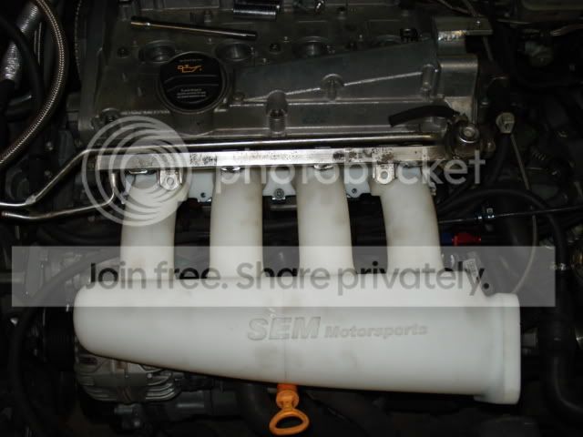
Modified by ruftwinturbo at 3:51 PM 1/8/2008
Our 3D printer made it possible for us to make a prototype so we can test fit before going into full production.
Modified by ruftwinturbo at 3:51 PM 1/8/2008