

Intake Manifold Design question never asked

Thread Starter
Joined: Aug 2004
Posts: 69
Likes: 0
From: chula vista, ca, usa
Why is it on headers that all runners lead to a common nice collector...even so on the turbo manifolds to promote the pulsing.
Now why isnt the same applied to intake manifolds.....have all the runners connect to a common collector ....instead of a plenum.....and have a throttle body on the end of the collector????

Now why isnt the same applied to intake manifolds.....have all the runners connect to a common collector ....instead of a plenum.....and have a throttle body on the end of the collector????
Honda-Tech Member
Joined: Jun 2004
Posts: 416
Likes: 0
From: Tempe, AZ, U.S.A.
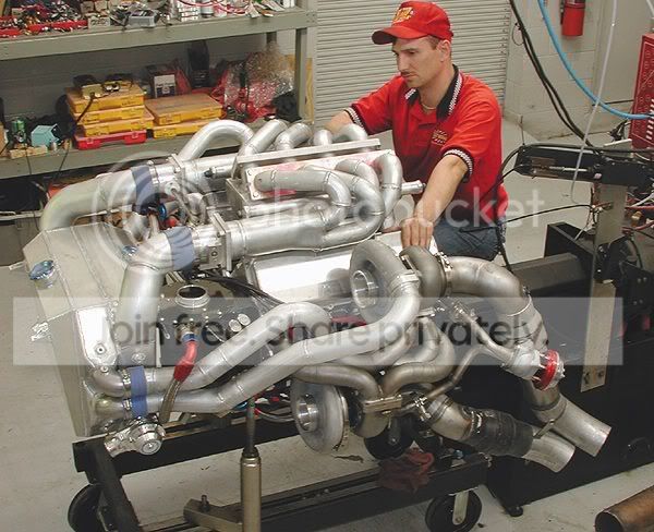
It's been done before; although it doesn't have quite a merge collector like the one you're showing. This is a BBC 472 cubic inch quad turbo motor. Notice how the twin intake manifolds are designed:
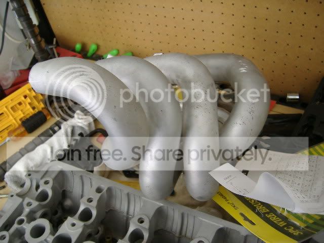
Bad picture, but here's something I was working on 2 years ago. The manifold is from a Toyota Corolla, but the distance between the runners are close enough to weld to a B-series head flange. I was building a turbo B-series motor, I never completed the project. I believe this setup would work better than a conventional intake manifold; the air distribution would be more even. If a single plenum manifold is not designed properly, you can starve the last cylinder that's feeding off of the plenum.
Bad picture, but here's something I was working on 2 years ago. The manifold is from a Toyota Corolla, but the distance between the runners are close enough to weld to a B-series head flange. I was building a turbo B-series motor, I never completed the project. I believe this setup would work better than a conventional intake manifold; the air distribution would be more even. If a single plenum manifold is not designed properly, you can starve the last cylinder that's feeding off of the plenum.
Honda-Tech Member
Joined: Oct 2003
Posts: 166
Likes: 0
From: AAlgaard, Rogaland, Norway
if your not running a plenum i would think, that at partial throttle 2 of the runners would get less airflow that the other two because of the angle on the butterfly valve, same if you used a giliotine style tb.
There was alot of research on this on i forget the car board but like stated at part throtle two of the runners near one side of the TB would get more air then the others. Unless you had a long collector then this would solve that problem. Also the toyota corolls and some ford FWD use this too

Honda-Tech Member
Joined: Apr 2002
Posts: 746
Likes: 0
From: downtown munson, munson, JAPAN
nice quad turbo set and all, but why do I see shitty wastegate set up? like 2 inch primary on header I guess and everything else and like like half inch  or something small tube is coming to wastegate. how V8 with 4 turbo regulating boost on with that.. amazing
I guess 60+psi dont really need bigger wastegate. I guess
or something small tube is coming to wastegate. how V8 with 4 turbo regulating boost on with that.. amazingI guess 60+psi dont really need bigger wastegate. I guess
Honda-Tech Member
Joined: May 2005
Posts: 38
Likes: 0
From: Charlotte, NC, United States
The pleneum acts as a spring for the resonant waves bouncing back from the intake valves. Unlike the exhaust side were you are trying to evenly space the pulses and they aren't reflected, the intake side of the motor reflects these pulses to create a sort of constructivness to achieve positive pressure in the manifold at a specific rpm. A collector on the intake side, which would essentally be a very small pleneum would have amazing throttle response but no high rpm support capability. This is why you see it on some oem applications. A collectored intake manifold would probably create some impressive top end #'s but would not be a good all around setup, just stick with a plenum type. If you want to learn more on this resonance, look up Helmholtz Resonance Calculations, also team-integra.net has a good article on this.
Edit:
And on that V8 above it does have a plenum, albeit a small one. And the very small wastgate tubes are probablly really good at fine boost control unlike an inconsistent huge tube that would cause a psi drop upon opening.
Modified by savestheday at 8:07 AM 4/26/2007
Edit:
And on that V8 above it does have a plenum, albeit a small one. And the very small wastgate tubes are probablly really good at fine boost control unlike an inconsistent huge tube that would cause a psi drop upon opening.
Modified by savestheday at 8:07 AM 4/26/2007

Honda-Tech Member
Joined: Jun 2006
Posts: 978
Likes: 0
From: Abbotsford, BC
I've been planning on building an intake manifold this way for quite some time now, except I am going to put a plenum on it.
Trending Topics
Thread Starter
Joined: Aug 2004
Posts: 69
Likes: 0
From: chula vista, ca, usa
<TABLE WIDTH="90%" CELLSPACING=0 CELLPADDING=0 ALIGN=CENTER><TR><TD>Quote, originally posted by savestheday »</TD></TR><TR><TD CLASS="quote">The pleneum acts as a spring for the resonant waves bouncing back from the intake valves. Unlike the exhaust side were you are trying to evenly space the pulses and they aren't reflected, the intake side of the motor reflects these pulses to create a sort of constructivness to achieve positive pressure in the manifold at a specific rpm. A collector on the intake side, which would essentally be a very small pleneum would have amazing throttle response but no high rpm support capability. This is why you see it on some oem applications. A collectored intake manifold would probably create some impressive top end #'s but would not be a good all around setup, just stick with a plenum type. If you want to learn more on this resonance, look up Helmholtz Resonance Calculations, also team-integra.net has a good article on this.
Edit:
And on that V8 above it does have a plenum, albeit a small one. And the very small wastgate tubes are probablly really good at fine boost control unlike an inconsistent huge tube that would cause a psi drop upon opening.
Modified by savestheday at 8:07 AM 4/26/2007</TD></TR></TABLE>
That sounnds like a very good answer, but until there are some dyno sheets or some hard data written in stone, I will back off from buying into it....
and also ...doesnt your answer only apply to normally aspirated motors????? (the resonance???)
for forced induction: the "collector design intake" would evenly distribute forced inducted air
Honda-Tech Member
Joined: Feb 2002
Posts: 9,455
Likes: 3
From: I heart tool, US
Anyone else notice how horribly small those two tubes going to the WG are?
leaves me to beleive this motor never actually ran.
But there is a purpose to a properlly designed plenum. It equalizes the intake pressure and volume that each cylinder receives. I'm sure Geoff or someone else could describe why a plenum is benefical.
I remember Cody actually tried this once, and ended up not using it.
Honda-Tech Member
Joined: Jun 2006
Posts: 978
Likes: 0
From: Abbotsford, BC
The wastegate tubes probably don't matter much as they probably aren't really used, the turbines are sized properly to the engine/manifolds/headflow etc. I've done this with my diesels, absolutely no wastegate, obviously the turbine needs to be sized very well to pull this off.

Honda-Tech Member
Joined: Aug 2004
Posts: 4,638
Likes: 0
From: Altamonte Springs/Orlando, Florida, USA
<TABLE WIDTH="90%" CELLSPACING=0 CELLPADDING=0 ALIGN=CENTER><TR><TD>Quote, originally posted by savestheday »</TD></TR><TR><TD CLASS="quote">The pleneum acts as a spring for the resonant waves bouncing back from the intake valves. Unlike the exhaust side were you are trying to evenly space the pulses and they aren't reflected, the intake side of the motor reflects these pulses to create a sort of constructivness to achieve positive pressure in the manifold at a specific rpm. A collector on the intake side, which would essentally be a very small pleneum would have amazing throttle response but no high rpm support capability. This is why you see it on some oem applications. A collectored intake manifold would probably create some impressive top end #'s but would not be a good all around setup, just stick with a plenum type. If you want to learn more on this resonance, look up Helmholtz Resonance Calculations, also team-integra.net has a good article on this.
Edit:
And on that V8 above it does have a plenum, albeit a small one. And the very small wastgate tubes are probablly really good at fine boost control unlike an inconsistent huge tube that would cause a psi drop upon opening.
</TD></TR></TABLE>
I want my 15 seconds or so back for reading this.
A common single throttle body plenum doesnt work well for distribution imo its like running at full speed and then trying to make a right turn into an intake runner.
All cylinders dont make the same horsepower, one cylinder will be colder one cylinder will be hotter. Distrubution matters a great deal.
<TABLE WIDTH="90%" CELLSPACING=0 CELLPADDING=0 ALIGN=CENTER><TR><TD>Quote, originally posted by Boostwerks.com »</TD></TR><TR><TD CLASS="quote">Anyone else notice how horribly small those two tubes going to the WG are?
leaves me to beleive this motor never actually ran.
</TD></TR></TABLE>
There's also two turbos it feeds off of and I would debate the need for a bigger wastegate. Would you want to run low boost on that engine?
<TABLE WIDTH="90%" CELLSPACING=0 CELLPADDING=0 ALIGN=CENTER><TR><TD>Quote »</TD></TR><TR><TD CLASS="quote">
But there is a purpose to a properlly designed plenum. It equalizes the intake pressure and volume that each cylinder receives. I'm sure Geoff or someone else could describe why a plenum is benefical.
</TD></TR></TABLE>
A plenum is to meet ( and exceed) the capacity of the cylinders its feeding if you want to meet the needs ( you got one big bitch of a plenum)
Honda-Tech Member
Joined: Jun 2004
Posts: 416
Likes: 0
From: Tempe, AZ, U.S.A.
<TABLE WIDTH="90%" CELLSPACING=0 CELLPADDING=0 ALIGN=CENTER><TR><TD>Quote, originally posted by hmongboyLS »</TD></TR><TR><TD CLASS="quote">something like this? Toyota corolla.
 </TD></TR></TABLE>
Yup, that's the engine my manifold came from. I still have it, with the flange and plenum cut off. Let me know if anybody wants it!
</TD></TR></TABLE>Yup, that's the engine my manifold came from. I still have it, with the flange and plenum cut off. Let me know if anybody wants it!
Honda-Tech Member
Joined: Feb 2002
Posts: 9,455
Likes: 3
From: I heart tool, US
<TABLE WIDTH="90%" CELLSPACING=0 CELLPADDING=0 ALIGN=CENTER><TR><TD>Quote, originally posted by MidShipCivic »</TD></TR><TR><TD CLASS="quote">
There's also two turbos it feeds off of and I would debate the need for a bigger wastegate. Would you want to run low boost on that engine?
</TD></TR></TABLE>
? that honestly makes no logical sense as an argument to what I said.
There's also two turbos it feeds off of and I would debate the need for a bigger wastegate. Would you want to run low boost on that engine?
</TD></TR></TABLE>
? that honestly makes no logical sense as an argument to what I said.
Honda-Tech Member
Joined: Aug 2004
Posts: 4,638
Likes: 0
From: Altamonte Springs/Orlando, Florida, USA
<TABLE WIDTH="90%" CELLSPACING=0 CELLPADDING=0 ALIGN=CENTER><TR><TD>Quote, originally posted by Boostwerks.com »</TD></TR><TR><TD CLASS="quote">
? that honestly makes no logical sense as an argument to what I said.
</TD></TR></TABLE>
BullShit .. If I ran a small wastegate on a large turbo setup I have no intention of running low boost because it wouldnt be capable of doing so.
? that honestly makes no logical sense as an argument to what I said.
</TD></TR></TABLE>
BullShit .. If I ran a small wastegate on a large turbo setup I have no intention of running low boost because it wouldnt be capable of doing so.
New User
Joined: Aug 2001
Posts: 364
Likes: 0
From: Gastonia, NC, US
All that piping looks to be aluminum, interesting. Should disepate heat but will they last.
Who's motor is that? I saw that Mike Moran on his Camaro "Casper" was trying to run the quad set up.
Who's motor is that? I saw that Mike Moran on his Camaro "Casper" was trying to run the quad set up.

Joined: Jan 2006
Posts: 838
Likes: 0
From: Fakeville, USA, USA
<TABLE WIDTH="90%" CELLSPACING=0 CELLPADDING=0 ALIGN=CENTER><TR><TD>Quote, originally posted by MidShipCivic »</TD></TR><TR><TD CLASS="quote">
BullShit .. If I ran a small wastegate on a large turbo setup I have no intention of running low boost because it wouldnt be capable of doing so. </TD></TR></TABLE>
Exactly. Most people have no clue the reason why a large capacity WG is needed.
They are used for low boost on large turbos. The reason is that you need to bypass so much of the exhaust to keep the turbine wheel under control. If you are running them to the max, most of the exhuast flow goes through the turbine, not the WG.
Honda-Tech Member
Joined: May 2005
Posts: 38
Likes: 0
From: Charlotte, NC, United States
<TABLE WIDTH="90%" CELLSPACING=0 CELLPADDING=0 ALIGN=CENTER><TR><TD>Quote, originally posted by MidShipCivic »</TD></TR><TR><TD CLASS="quote">I want my 15 seconds or so back for reading this.
A common single throttle body plenum doesnt work well for distribution imo its like running at full speed and then trying to make a right turn into an intake runner.
All cylinders dont make the same horsepower, one cylinder will be colder one cylinder will be hotter. Distrubution matters a great deal.
</TD></TR></TABLE>
I can't give you any hard data to show against what you're saying, but in reality the air coming into a plenum style manifold is not a constant flow sort of thing that needs to be directed evenly into each cylinder. The valves opening and closing are sort of an on/off switch for needed air supply. In a full throttle environment (no vacuum) no cylinder will be starved for air, unless the engine is at a considerably high rpm, the far wall of the plenum is poorly designed, and the cylinders are fighting for the available volume of air.
I would assume this is why most forced induction manifold have large plenums, to support the needed volume of air. Engine displacment X Boost = Plenum size, sort of thing.
Don't take any of this as fact, i'm just speculating. A plenum manifold might work well, but i think it would create a good bit of surging on throttle input and not make as much power as a well designed harmonic manifold.
- Geoff

Thread
Thread Starter
Forum
Replies
Last Post
mkw1
Welding / Fabrication
34
Aug 11, 2008 04:43 PM
burnt_rice
Honda CRX / EF Civic (1988 - 1991)
6
May 6, 2007 12:48 PM