


HONDA sensors resistance chart. anyone has it?

Thread Starter
Honda-Tech Member
Joined: Mar 2004
Posts: 7,434
Likes: 2
hello everyone.
i remember back from 04 that there was a list of all the sensors in hondas.
such as ect iat map tps (rpm?)
if anyone have it and can post it up itll be gr8.
thanks
i remember back from 04 that there was a list of all the sensors in hondas.
such as ect iat map tps (rpm?)
if anyone have it and can post it up itll be gr8.
thanks
Mad Scientist
Joined: Nov 2002
Posts: 5,827
Likes: 1
From: tallafizzy, FL state
Ecu locations are for OBD1 ONLY let me know and ill add others
***<U>Ignition coil :</U>
primary resistance: .6 - .8 ohms (blk/yel)
secondary res. : 12.8 - 19.2 Kohms (wht/blu)
***<U>ECT fan switch :</U> (green - black wires)
A and B terminals should test for continuity above 196 - 203*F
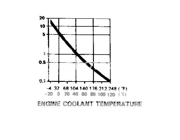
***<U>ECT sensor :</U> (RED/WHT= D13 * GRN/BLU= D22)
output not linear
k-ohm: temp (celsius)(*F)
12 - ( -20) (-4)
5.0 - 0 (32)
2.0 - 20 (68)
1.2 - 40 (104)
0.7 - 60 (140)
0.4 - 80 (176)
0.2 - 100 (212)
0.1 - 120 (248)
***<U>VSS :</U> (-BLK= A24 * 12v+BLK/YEL= main relay * +ORN=B10)
should be 5V between ORN and Blk terminals
sensor pulses between 0-10v.
***<U>Oil pressure switch :</U> (YEL/RED)
terminal on switch is + positive; should be continuity with ground when no oil pressure. triggers when pressure is under 4.3psi
***<U>ECT sending unit :</U> (YEL/GRN)
At 133*F = 137 ohms
At 185 - 212*F = 46-30 ohms
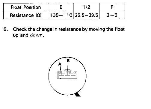
***<U>Fuel gauge sending unit :</U>
check resistance between A-B terminals
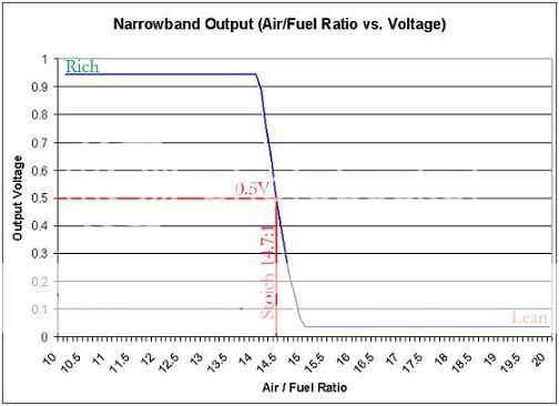
***<U>heated oxygen sensor :</U> (GRN/BLU= D22 * ORN/BLK= A6 * YEL/BLK= B1 * WHT/RED= D14)
1.0v volt range; 1 volt being rich
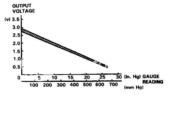
***<U>MAP :</U> (GRN/WHT= D21 * WHT/YEL= D17 * YEL/WHT= D19) yel/wht can also be yel/red
linear output
around 2.84v at 0 in-hg
around .50v at 26 in-hg
***<U>TPS :</U> (YEL/BLU= D20 * RED/BLK= D11 * GRN/BLU= D22)
.5v at full closed throttle
4.0v at full open
***<U>IAT :</U> (RED/YEL= D15 GRN/BLU = D22)
k-ohm: temp (celsius)(*F)
12 - ( -20) (-4)
5.0 - 0 (32)
2.0 - 20 (68)
1.2 - 40 (104)
0.7 - 60 (140)
0.4 - 80 (176)
0.2 - 100 (212)
0.1 - 120 (248)
***<U>Baro sensor :</U>
shiet breaks, change it or the ecu or disable on rom
***<U>ELD : </U> (BLK/YEL - GRN/RED - BLK) (grn/red = D10)
blk/yel(+) and blk(-) should get batt. voltage
grn/red terminal to ground should give you 5v
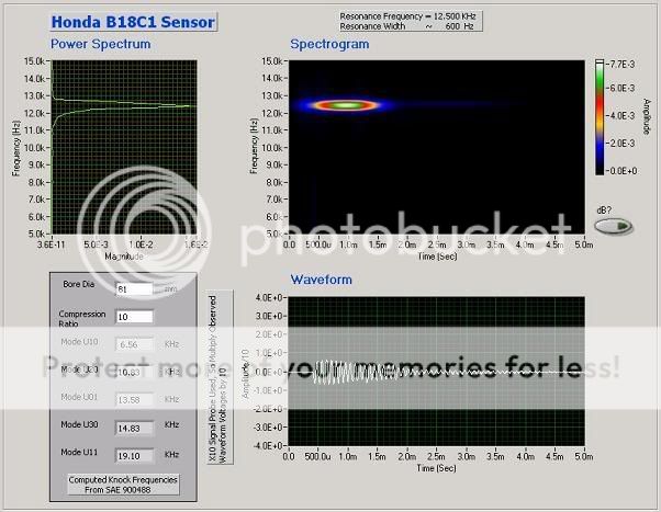
***<U>knock sensor :</U> (RED/BLU) ( D3)
Here is a graph with a study done by BigMoose, hope you dont mind me using it.
***<U>IACV :</U> (-YEL/BLK - BLK/BLU) (yel/blk= B1 blk/blu = A9)
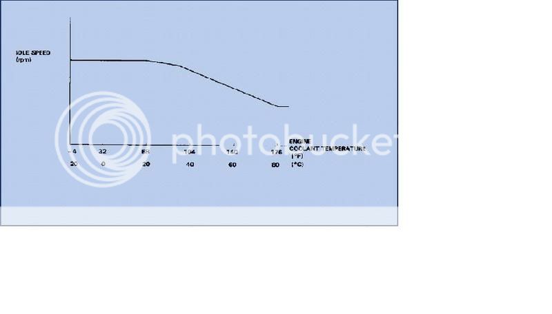
***<U>FITV :</U> (only for obd0-1)
Non eletronic;
It prevents erratic running when cold, by rising idle speed. The valve is controlled by a thermowax plunger. When engine coolant is cold, it contracts the plunger allowing for more air to enter the engine, when coolant gets to operating temp. the plunger closes.
***<U>TDC/CYP/CKP sensors</U>
TDC: ORN/BLU - WHT/BLU (b13- b14)
CYP: ORN - WHT (b11- b12)
CKP: BLU/GRN - BLU/YEL (b15 - b16)
Modified by mmuller at 1:25 PM 11/23/2006
Modified by mmuller at 1:26 PM 11/23/2006
***<U>Ignition coil :</U>
primary resistance: .6 - .8 ohms (blk/yel)
secondary res. : 12.8 - 19.2 Kohms (wht/blu)
***<U>ECT fan switch :</U> (green - black wires)
A and B terminals should test for continuity above 196 - 203*F
***<U>ECT sensor :</U> (RED/WHT= D13 * GRN/BLU= D22)
output not linear
k-ohm: temp (celsius)(*F)
12 - ( -20) (-4)
5.0 - 0 (32)
2.0 - 20 (68)
1.2 - 40 (104)
0.7 - 60 (140)
0.4 - 80 (176)
0.2 - 100 (212)
0.1 - 120 (248)
***<U>VSS :</U> (-BLK= A24 * 12v+BLK/YEL= main relay * +ORN=B10)
should be 5V between ORN and Blk terminals
sensor pulses between 0-10v.
***<U>Oil pressure switch :</U> (YEL/RED)
terminal on switch is + positive; should be continuity with ground when no oil pressure. triggers when pressure is under 4.3psi
***<U>ECT sending unit :</U> (YEL/GRN)
At 133*F = 137 ohms
At 185 - 212*F = 46-30 ohms
***<U>Fuel gauge sending unit :</U>
check resistance between A-B terminals
***<U>heated oxygen sensor :</U> (GRN/BLU= D22 * ORN/BLK= A6 * YEL/BLK= B1 * WHT/RED= D14)
1.0v volt range; 1 volt being rich
***<U>MAP :</U> (GRN/WHT= D21 * WHT/YEL= D17 * YEL/WHT= D19) yel/wht can also be yel/red
linear output
around 2.84v at 0 in-hg
around .50v at 26 in-hg
***<U>TPS :</U> (YEL/BLU= D20 * RED/BLK= D11 * GRN/BLU= D22)
.5v at full closed throttle
4.0v at full open
***<U>IAT :</U> (RED/YEL= D15 GRN/BLU = D22)
k-ohm: temp (celsius)(*F)
12 - ( -20) (-4)
5.0 - 0 (32)
2.0 - 20 (68)
1.2 - 40 (104)
0.7 - 60 (140)
0.4 - 80 (176)
0.2 - 100 (212)
0.1 - 120 (248)
***<U>Baro sensor :</U>
shiet breaks, change it or the ecu or disable on rom
***<U>ELD : </U> (BLK/YEL - GRN/RED - BLK) (grn/red = D10)
blk/yel(+) and blk(-) should get batt. voltage
grn/red terminal to ground should give you 5v
***<U>knock sensor :</U> (RED/BLU) ( D3)
Here is a graph with a study done by BigMoose, hope you dont mind me using it.
***<U>IACV :</U> (-YEL/BLK - BLK/BLU) (yel/blk= B1 blk/blu = A9)
***<U>FITV :</U> (only for obd0-1)
Non eletronic;
It prevents erratic running when cold, by rising idle speed. The valve is controlled by a thermowax plunger. When engine coolant is cold, it contracts the plunger allowing for more air to enter the engine, when coolant gets to operating temp. the plunger closes.
***<U>TDC/CYP/CKP sensors</U>
TDC: ORN/BLU - WHT/BLU (b13- b14)
CYP: ORN - WHT (b11- b12)
CKP: BLU/GRN - BLU/YEL (b15 - b16)
Modified by mmuller at 1:25 PM 11/23/2006
Modified by mmuller at 1:26 PM 11/23/2006
Thread Starter
Honda-Tech Member
Joined: Mar 2004
Posts: 7,434
Likes: 2
COO....
ill start with what i got. (by haynes manual!)
IAT\IATS and ECT\CTS has the same resistance.
k-ohm: temp (celsius)
12 - ( -20)
5.0 - 0
2.0 - 20
1.2 - 40
0.7 - 60
0.4 - 80
ill start with what i got. (by haynes manual!)
IAT\IATS and ECT\CTS has the same resistance.
k-ohm: temp (celsius)
12 - ( -20)
5.0 - 0
2.0 - 20
1.2 - 40
0.7 - 60
0.4 - 80
Thread Starter
Honda-Tech Member
Joined: Mar 2004
Posts: 7,434
Likes: 2
MAP sensor Voltage:
volts: mmHg:
3 = 0
2.5 = 125
2 = 250
1.5 = 375
1 = 500
0.5 = 625
-----------------------------------------------------------------------------
TPS sensor Voltage:
throttle CLOSED: 0.5v
throttle OPEN: 4.5v
volts: mmHg:
3 = 0
2.5 = 125
2 = 250
1.5 = 375
1 = 500
0.5 = 625
-----------------------------------------------------------------------------
TPS sensor Voltage:
throttle CLOSED: 0.5v
throttle OPEN: 4.5v
Trending Topics
i HAS questions ?
Joined: Feb 2003
Posts: 7,850
Likes: 0
From: OH
Random question, but if the ECT and IAT sensors have the same resistance, has anyone ever used one in place of the other? (e.g. ECT sensor in place of IAT sensor)
i HAS questions ?
Joined: Feb 2003
Posts: 7,850
Likes: 0
From: OH
The ECU makes fuel corrections according to both the ECT and IAT sensors. I'm wondering if anyone has used one in place of the other before. I'm referring to the sensor, not the fan switch.


Honda-Tech Member
Joined: May 2018
Posts: 520
Likes: 1
From: Cental North Carolina


Honda-Tech Member
Joined: May 2018
Posts: 520
Likes: 1
From: Cental North Carolina

Thread
Thread Starter
Forum
Replies
Last Post