

What do you think of my new intake manifold for my SFWD car

Thread Starter
Joined: Mar 2003
Posts: 210
Likes: 0
From: Atco, nj, USA
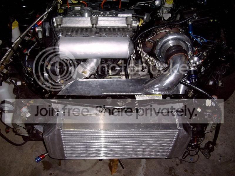
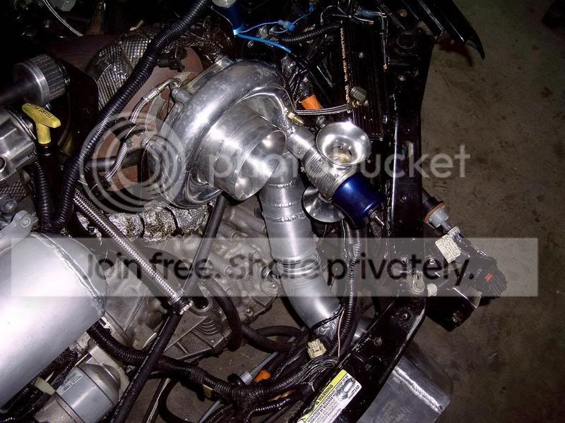
I decided to take a different route than the norm. I wanted to style this after some Indy and F1 intake manifolds. There is a 1 3/4" plate that gets sandwiched between this manifold and the head. It is made of a material that will not heatsoak. It contains the injector bungs and the bosses for the fuel rail.
Let me know what you think!
Let me know what you think!
Thread Starter
Joined: Mar 2003
Posts: 210
Likes: 0
From: Atco, nj, USA
I will let you know. I had an issue with valve float and I just got the part to correct it. With the car braking up it ran an 11.0 @130mph

Joined: Oct 2002
Posts: 1,708
Likes: 0
From: Eagle Mountain, UT, USA
What material did you find that won't heat soak? As long as the head is heat soaked won't something bolted right to the head be hot as long as the head is?
Honda-Tech Member
Joined: Jan 2003
Posts: 3,788
Likes: 0
From: Charlotte, NC
I would do something about the entrance to the runners add air horns or something. Most indy and F1 intake manifold involve Individual throttels for each running with some type of air horn of a calculated length radius etc. with calculated runner lengths and plenum volumes, your runners look like as mentioned above for 12k rpm engine
Trending Topics
Thread Starter
Joined: Mar 2003
Posts: 210
Likes: 0
From: Atco, nj, USA
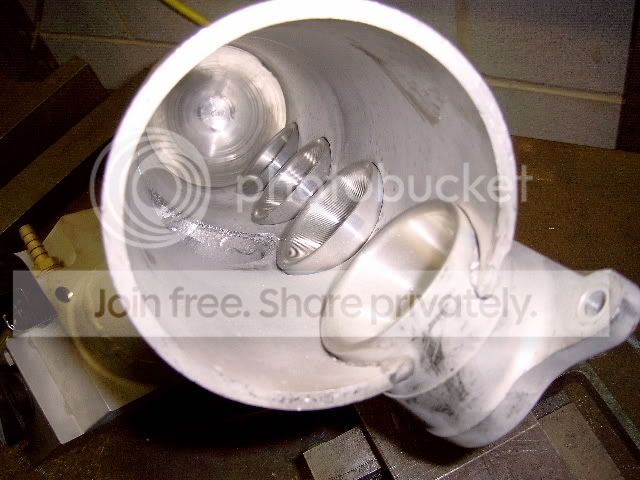
There is extra length with the injector plate for a total of 4" of runner length. Also look closer the mouths are a tapered bell and are at minimal 1/4" in the plentum. I got this flange from Darrell *** which is the same that he uses in his SRT.
Modified by Blitzkrieg at 9:28 PM 9/29/2006
Modified by Blitzkrieg at 10:27 PM 10/1/2006
Modified by Blitzkrieg at 9:28 PM 9/29/2006
Modified by Blitzkrieg at 10:27 PM 10/1/2006
Honda-Tech Member
Joined: Jan 2004
Posts: 1,044
Likes: 0
From: Land of the Lost, usa
<TABLE WIDTH="90%" CELLSPACING=0 CELLPADDING=0 ALIGN=CENTER><TR><TD>Quote, originally posted by Fabman »</TD></TR><TR><TD CLASS="quote">can you say ips  </TD></TR></TABLE>
too bad they dont sell them.
</TD></TR></TABLE>too bad they dont sell them.

Thread Starter
Joined: Mar 2003
Posts: 210
Likes: 0
From: Atco, nj, USA
Are you suggesting that this wasn't planned or thought out?
The diameter is 4" internal on the plentum with a target RPM range of 8500.
The runners are 4" long not the 5 I posted above. There are bell mouths CNCed into the flange which extend into the plenum 1/4". All is port matched to the head.
This is the exact same runner length that Darrell *** uses with his car that just ran a 7.9 @ 188mph. The only difference is the diameter of the plenum, slightly larger head ports, and air flow from the end of the plenum vs. the middle. I have read on F-1 websites that center airflow interduction creats a better airflow balance between the cylinders and less chance of blow by or syphoning of the 1st cylinder nor over feeding the 4th cylinder. I didn't build this for the sake of building it. I built this whit input from Darrell on the Crawford car as well as research into indy and f-1 builds.
I hope to have the car finished this week and get some runs. We can all talk then

Honda-Tech Member
Joined: Jan 2003
Posts: 3,788
Likes: 0
From: Charlotte, NC
<TABLE WIDTH="90%" CELLSPACING=0 CELLPADDING=0 ALIGN=CENTER><TR><TD>Quote, originally posted by Blitzkrieg »</TD></TR><TR><TD CLASS="quote">Are you suggesting that this wasn't planned or thought out?
The diameter is 4" internal on the plentum with a target RPM range of 8500.
The runners are 4" long not the 5 I posted above. There are bell mouths CNCed into the flange which extend into the plenum 1/4". All is port matched to the head.
This is the exact same runner length that Darrell *** uses with his car that just ran a 7.9 @ 188mph. The only difference is the diameter of the plenum, slightly larger head ports, and air flow from the end of the plenum vs. the middle. I have read on F-1 websites that center airflow interduction creats a better airflow balance between the cylinders and less chance of blow by or syphoning of the 1st cylinder nor over feeding the 4th cylinder. I didn't build this for the sake of building it. I built this whit input from Darrell on the Crawford car as well as research into indy and f-1 builds.
I hope to have the car finished this week and get some runs. We can all talk then </TD></TR></TABLE>
err this is really hard to make much sense of but let's start here i don't know what formula 1 stuff you read but it seems you may not have read the whole thing.
I'm not sure when F1 used a plenum of that style (maybe back in the turbo era) but without doing some extensive modeling or calculations I don't think your going to be able to tell what cylinder is stealing air from what portion of the plenum. It is a well known fact in that a modern day formulas 1 airbox that cylinder let's say 8 (rear most of the motor) may actually be using fuel present from cylinder # 1 (furthest away) What exact reasearch into indy and f1 build did you do. Not be a dick but this looks nothing like anything I have seen them build....
The diameter is 4" internal on the plentum with a target RPM range of 8500.
The runners are 4" long not the 5 I posted above. There are bell mouths CNCed into the flange which extend into the plenum 1/4". All is port matched to the head.
This is the exact same runner length that Darrell *** uses with his car that just ran a 7.9 @ 188mph. The only difference is the diameter of the plenum, slightly larger head ports, and air flow from the end of the plenum vs. the middle. I have read on F-1 websites that center airflow interduction creats a better airflow balance between the cylinders and less chance of blow by or syphoning of the 1st cylinder nor over feeding the 4th cylinder. I didn't build this for the sake of building it. I built this whit input from Darrell on the Crawford car as well as research into indy and f-1 builds.
I hope to have the car finished this week and get some runs. We can all talk then
</TD></TR></TABLE>err this is really hard to make much sense of but let's start here i don't know what formula 1 stuff you read but it seems you may not have read the whole thing.
I'm not sure when F1 used a plenum of that style (maybe back in the turbo era) but without doing some extensive modeling or calculations I don't think your going to be able to tell what cylinder is stealing air from what portion of the plenum. It is a well known fact in that a modern day formulas 1 airbox that cylinder let's say 8 (rear most of the motor) may actually be using fuel present from cylinder # 1 (furthest away) What exact reasearch into indy and f1 build did you do. Not be a dick but this looks nothing like anything I have seen them build....
Joined: Oct 2002
Posts: 1,708
Likes: 0
From: Eagle Mountain, UT, USA
<TABLE WIDTH="90%" CELLSPACING=0 CELLPADDING=0 ALIGN=CENTER><TR><TD>Quote, originally posted by Blitzkrieg »</TD></TR><TR><TD CLASS="quote"> I didn't build this for the sake of building it. I built this whit input from Darrell on the Crawford car as well as research into indy and f-1 builds.
I hope to have the car finished this week and get some runs. We can all talk then </TD></TR></TABLE>
How do Indy or F1 builds relate to what you are doing? I guess your engine has pistons and rods but other than that what sort of useful can you gain from them. I assume your manifold is purpose buit for drag racing as well not road or oval racing. I mean don't F1 cars idle at like 4-5K RPM? Those motors are in your rev range probably 5% of the time and I'm sure they are optimized for much higher power bands.
The other issue is even running a fast time doesn't mean this thing works unless you run it against something else for comparison, I mean who knows if you could have made more power with a factory manifold if there is no back to back comparison. Props for building a manifold yourself but why do you suppose that a 4" tube shape is optimized as the collector? Does a perfect cylinder shape optimize efficiency or was it just to do something different or because its easy to get a pipe, weld ends on and fab some runners? I'm no expert but I'm just posing some questions to understand why you did it like this as opposed to some other way.
I hope to have the car finished this week and get some runs. We can all talk then
</TD></TR></TABLE>How do Indy or F1 builds relate to what you are doing? I guess your engine has pistons and rods but other than that what sort of useful can you gain from them. I assume your manifold is purpose buit for drag racing as well not road or oval racing. I mean don't F1 cars idle at like 4-5K RPM? Those motors are in your rev range probably 5% of the time and I'm sure they are optimized for much higher power bands.
The other issue is even running a fast time doesn't mean this thing works unless you run it against something else for comparison, I mean who knows if you could have made more power with a factory manifold if there is no back to back comparison. Props for building a manifold yourself but why do you suppose that a 4" tube shape is optimized as the collector? Does a perfect cylinder shape optimize efficiency or was it just to do something different or because its easy to get a pipe, weld ends on and fab some runners? I'm no expert but I'm just posing some questions to understand why you did it like this as opposed to some other way.
Thread Starter
Joined: Mar 2003
Posts: 210
Likes: 0
From: Atco, nj, USA
When I was building this intake and designing it, I had a former Grantelli designer fabricator working through the numbers with me. Given the target RPM, Pressure Ratio, and VE of the engine the 14" long x 4" diameter plenum x, 4" runner was optimal. FYI I am running an automatic with an efficient converter that hold around 8k rpms thru each gear, so imagine the entire 1/4 @ 8k rpms. This is what this intake was designed for. In other words other than the 4500 stall speed at the line I run 8k rpms and that is it. My setup doesn't rev up and down the rpms like you 5 speed Hondas This is why I have a short runner.
This is why I have a short runner.
Honda-Tech Member
Joined: Feb 2003
Posts: 6,672
Likes: 8
From: Michigan
<TABLE WIDTH="90%" CELLSPACING=0 CELLPADDING=0 ALIGN=CENTER><TR><TD>Quote, originally posted by crx12 »</TD></TR><TR><TD CLASS="quote">Also what is that material you have against the head?</TD></TR></TABLE>
i'm interested too
i'm interested too
Honda-Tech Member
Joined: Sep 2005
Posts: 201
Likes: 0
From: Los Angeles
****! MAYBE HE SHOULD JUST KEEP HIS IDEAS AND HARD WORK TO HIMSELF. EVEN WITH ALL OF YOUR, "I KNOW MORE THAN YOU TALK", NONE OF YOU COULD EVER SAY AT THIS POINT IF IT WILL WORK.
IT ALMOST SEEMS LIKE YOU PEOPLE GET PISSED OFF BECAUSE THIS GUY DOES NOT THINK LIKE YOU. CHILL THE expletive OUT.
SORRY I AM HAVING A BAD DAY AND ALL I SEE IS BITCH, BITCH, BITCH. YOUR NOT ******* COOLER THAN EVERYONE. SAME OLD HONDA-TEC ****.
IT ALMOST SEEMS LIKE YOU PEOPLE GET PISSED OFF BECAUSE THIS GUY DOES NOT THINK LIKE YOU. CHILL THE expletive OUT.
SORRY I AM HAVING A BAD DAY AND ALL I SEE IS BITCH, BITCH, BITCH. YOUR NOT ******* COOLER THAN EVERYONE. SAME OLD HONDA-TEC ****.
Thread Starter
Joined: Mar 2003
Posts: 210
Likes: 0
From: Atco, nj, USA
Don't laugh because it works. I use a hard wood that is treated and sealed. It does an exceptional job of keeping the heat away from the intake manifold. The ports match perfectly. For the injector bungs I pressed in brass bosses. I pressure tested this setup at over 60psi with no leaks.