

Pics of my new ITB manifold -- built by me

Thread Starter
Honda-Tech Member
iTrader: (1)
Joined: Apr 2004
Posts: 2,876
Likes: 3
From: Burnout Box, IA, U.S.A.
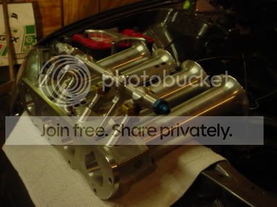
ok so i finally took some pics of this thing for you all to see. i designed and built this all myself. let me know what you think.
Thread Starter
Honda-Tech Member
iTrader: (1)
Joined: Apr 2004
Posts: 2,876
Likes: 3
From: Burnout Box, IA, U.S.A.
probably about 50 hrs of machine time and tons more design time. this is actually the 5th manifold i've done, they've all been different but if you fiure all that design and developement time it really adds up.
i made this before i quit my last job so the material was "donated" and all it really cost was my time.
i made this before i quit my last job so the material was "donated" and all it really cost was my time.
Honda-Tech Member
Joined: Apr 2005
Posts: 591
Likes: 0
From: NH
damn, they look nice. props for the custom work. gotta love "donated" material down with the man!
How do you plan on tuning them? i dont see anywhere to mount a tps. . .

How do you plan on tuning them? i dont see anywhere to mount a tps. . .
Thread Starter
Honda-Tech Member
iTrader: (1)
Joined: Apr 2004
Posts: 2,876
Likes: 3
From: Burnout Box, IA, U.S.A.
<TABLE WIDTH="90%" CELLSPACING=0 CELLPADDING=0 ALIGN=CENTER><TR><TD>Quote, originally posted by syntax420 »</TD></TR><TR><TD CLASS="quote">damn, they look nice. props for the custom work. gotta love "donated" material down with the man!
How do you plan on tuning them? i dont see anywhere to mount a tps. . .
</TD></TR></TABLE>
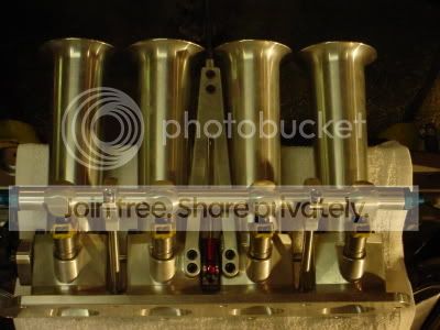
if you look at the 2nd pic to the left theres a piece of aluminum bolted to that tb which the tps mounts to. its there you just cant tell cuz the background is black.
vac lines will run out the bottom of each tb to a canister to run the map sensor.
air temp sensor will be on the bottom of the first tube also.
the last one i built ran fine without idle control so hopefully this will too.
i tune with an aem ems also
How do you plan on tuning them? i dont see anywhere to mount a tps. . .
</TD></TR></TABLE>if you look at the 2nd pic to the left theres a piece of aluminum bolted to that tb which the tps mounts to. its there you just cant tell cuz the background is black.
vac lines will run out the bottom of each tb to a canister to run the map sensor.
air temp sensor will be on the bottom of the first tube also.
the last one i built ran fine without idle control so hopefully this will too.
i tune with an aem ems also
Trending Topics
Honda-Tech Member

Joined: Aug 2004
Posts: 1,775
Likes: 0
From: SLC, USA
That's definately some nice work, unlike most DIY Itb's.
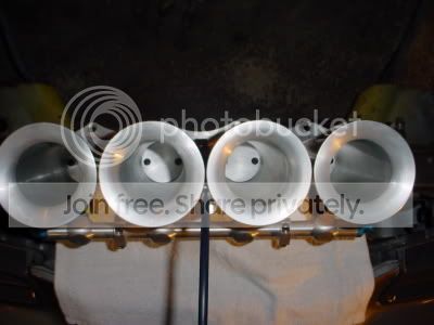
I'm curious how having the actual butterfly plates so close to the head effects the dynamics of the airflow? I always assumed you want the plates generally further away from the head.
I'm curious how having the actual butterfly plates so close to the head effects the dynamics of the airflow? I always assumed you want the plates generally further away from the head.
Thread Starter
Honda-Tech Member
iTrader: (1)
Joined: Apr 2004
Posts: 2,876
Likes: 3
From: Burnout Box, IA, U.S.A.
<TABLE WIDTH="90%" CELLSPACING=0 CELLPADDING=0 ALIGN=CENTER><TR><TD>Quote, originally posted by 2lude4u »</TD></TR><TR><TD CLASS="quote">That's definately some nice work, unlike most DIY Itb's.
I'm curious how having the actual butterfly plates so close to the head effects the dynamics of the airflow? I always assumed you want the plates generally further away from the head.</TD></TR></TABLE>
well you could be very right on that. my last design did use the tb's further up in the tube but was more complicated and took more pieces. i've seen it both ways as with the fuel injector placement too. i think the blade is far enough back and the port is deep enough in the head that it wont affect the air too much as its curving down into the cylinder. the flange is angled too (you cant see it in the picture) but when at full throttle the airflow path should point directly towards the valve.
Junior Member
Joined: Jul 2005
Posts: 43
Likes: 0
From: Louisville, KY, US
it seems like the extra turbulence caused by the butterfly valve located that close to the injector would help stir up the fuel resulting in better combustion. I LIKE IT
Modified by AngryJeremy at 2:31 PM 2/13/2006
Modified by AngryJeremy at 2:31 PM 2/13/2006


Honda-Tech Member
Joined: Aug 2003
Posts: 16,979
Likes: 0
From: SOCAL
<TABLE WIDTH="90%" CELLSPACING=0 CELLPADDING=0 ALIGN=CENTER><TR><TD>Quote, originally posted by PrecisionH23a »</TD></TR><TR><TD CLASS="quote">Very sexy
If it performs as well as it looks you should consider manufacturing these.</TD></TR></TABLE>
agreed... please keep us posted on the results.
If it performs as well as it looks you should consider manufacturing these.</TD></TR></TABLE>
agreed... please keep us posted on the results.