

Found a picture of this intake manifold........??

Thread Starter
Honda-Tech Member
Joined: Jun 2002
Posts: 6,939
Likes: 2
From: Maryland, USA
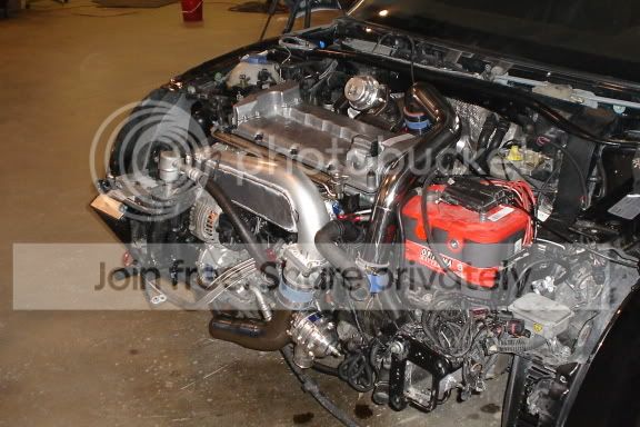
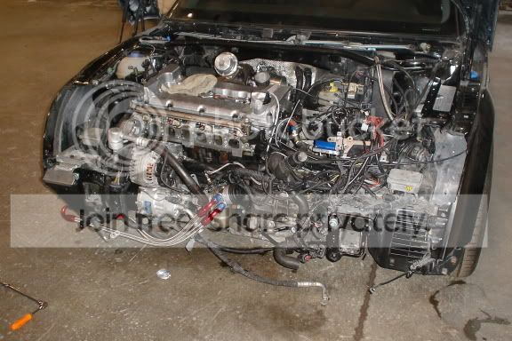
just figured i'd throw it up for discussion....think it would work? its in an Audi TT never seen one like this before..... im skeptical
Joined: Mar 2005
Posts: 110
Likes: 0
That does look like it would work. It flows really evenly from the side over the top. Maybe that car has ITB's. Ive seen alot of oddly designed Audi manifolds, but the seem to work really well.

i HAS questions ?
Joined: Feb 2003
Posts: 7,850
Likes: 0
From: OH
<TABLE WIDTH="90%" CELLSPACING=0 CELLPADDING=0 ALIGN=CENTER><TR><TD>Quote, originally posted by Pit Guy »</TD></TR><TR><TD CLASS="quote">24v Vr6 tt Nice  </TD></TR></TABLE>
Um that looks like a 20V 1.8T to me.
</TD></TR></TABLE>Um that looks like a 20V 1.8T to me.
Honda-Tech Member
Joined: Dec 2004
Posts: 294
Likes: 0
From: Manhattan Beach, CA, USA
<TABLE WIDTH="90%" CELLSPACING=0 CELLPADDING=0 ALIGN=CENTER><TR><TD>Quote, originally posted by daveG »</TD></TR><TR><TD CLASS="quote">
Um that looks like a 20V 1.8T to me. </TD></TR></TABLE>
Yeah, but its not....its a 24V VR. 1.8T got the oil cap on the other side.
Um that looks like a 20V 1.8T to me. </TD></TR></TABLE>
Yeah, but its not....its a 24V VR. 1.8T got the oil cap on the other side.
Trending Topics

i HAS questions ?
Joined: Feb 2003
Posts: 7,850
Likes: 0
From: OH
<TABLE WIDTH="90%" CELLSPACING=0 CELLPADDING=0 ALIGN=CENTER><TR><TD>Quote, originally posted by LBHgti »</TD></TR><TR><TD CLASS="quote">Yeah, but its not....its a 24V VR. 1.8T got the oil cap on the other side. </TD></TR></TABLE>
Good call. I don't know jack about VWs.
Good call.
I don't know jack about VWs.
Junior Member
Joined: May 2004
Posts: 122
Likes: 0
From: Millville, NJ, USA
That intake would be even better if it allowed for the different runner distances inside the head. There's about 3.5" difference between front and rear cylinders.
thats also a 3.2 and not a 2.8
thats also a 3.2 and not a 2.8
Honda-Tech Member
Joined: Jul 2004
Posts: 500
Likes: 0
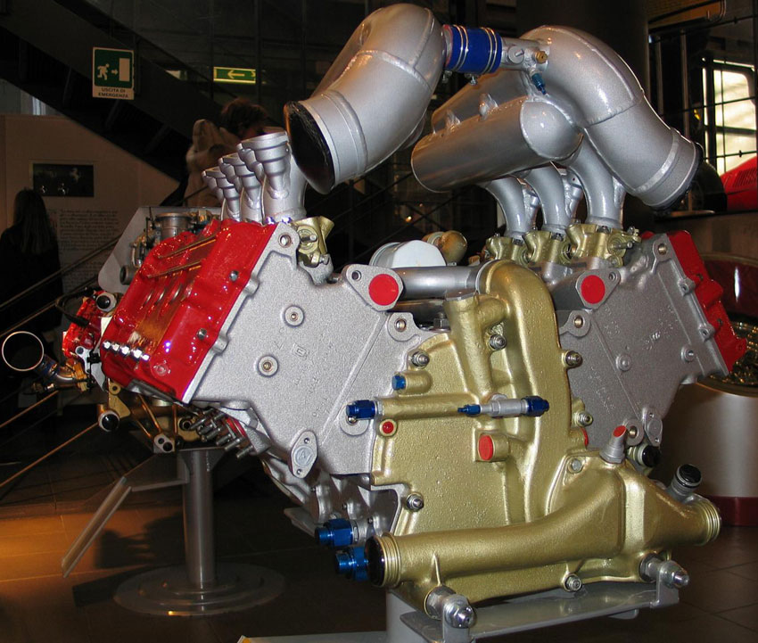
I don't know how well it will work, but I have incoperated a similar idea into a manifold I am building. It uses a cone though that feeds thru a certain area. My reason behind this is to make the velocity of the air in the cone relatively constant. To do this, you have to decrease the area of the tube as it passes area that air can flow out of.
The idea behind all of this is to equalize airflow between all the cylinders. Instead of blowing directly across the top of one runner, you blow air at all the runners at an equal amount. If that makes any sense.
The idea behind all of this is to equalize airflow between all the cylinders. Instead of blowing directly across the top of one runner, you blow air at all the runners at an equal amount. If that makes any sense.
i HAS questions ?
Joined: Feb 2003
Posts: 7,850
Likes: 0
From: OH
<TABLE WIDTH="90%" CELLSPACING=0 CELLPADDING=0 ALIGN=CENTER><TR><TD>Quote, originally posted by 99_GS-T »</TD></TR><TR><TD CLASS="quote">I don't know how well it will work, but I have incoperated a similar idea into a manifold I am building. It uses a cone though that feeds thru a certain area. My reason behind this is to make the velocity of the air in the cone relatively constant. To do this, you have to decrease the area of the tube as it passes area that air can flow out of.
The idea behind all of this is to equalize airflow between all the cylinders. Instead of blowing directly across the top of one runner, you blow air at all the runners at an equal amount. If that makes any sense.</TD></TR></TABLE>
Like a taper towards the cylinders furthest from the throttle body?
The idea behind all of this is to equalize airflow between all the cylinders. Instead of blowing directly across the top of one runner, you blow air at all the runners at an equal amount. If that makes any sense.</TD></TR></TABLE>
Like a taper towards the cylinders furthest from the throttle body?


Honda-Tech Member
Joined: Jul 2004
Posts: 500
Likes: 0
Who is making those? That is VERY similiar to the design I am planning on using. Actually, almost identical on the design layout. I wnet about it in a slightly different manner, but it will most likely act the same way.
Anybody have some testing results from similar manifolds showing if it works or not?
Anybody have some testing results from similar manifolds showing if it works or not?
Who is Mr Robot?
iTrader: (2)
Joined: Jul 2004
Posts: 21,474
Likes: 10
From: ATL - Where the Pimps and Players dwell
<TABLE WIDTH="90%" CELLSPACING=0 CELLPADDING=0 ALIGN=CENTER><TR><TD>Quote, originally posted by LBHgti »</TD></TR><TR><TD CLASS="quote">
Yeah, but its not....its a 24V VR. 1.8T got the oil cap on the other side. </TD></TR></TABLE>
its a vr6....
Yeah, but its not....its a 24V VR. 1.8T got the oil cap on the other side. </TD></TR></TABLE>
its a vr6....


Honda-Tech Member
Joined: Aug 2005
Posts: 969
Likes: 0
From: abbotsford, bc, canada
does anyone else see those pointy things on the turbo outlets... it looks like something off the back of a jet engine.
what is it? does it reduce turbulence when exhaust comes outta the turbine?
what is it? does it reduce turbulence when exhaust comes outta the turbine?
Guest
Posts: n/a

Joined: Dec 2002
Posts: 1,506
Likes: 1
From: manchester, nh, us
some kid thats into vw near me makes them that way. The cone design has a small channel designed to distribute equal amounts of air into the manifold at wot
Honda-Tech Member
Joined: Jul 2003
Posts: 1,544
Likes: 0
From: Portland, Oregon, USA
From what I can tell there would be more pumping losses from this style intake manifold. It physically distributes the air evenly, where as a properly shapped plenum realize on pressure gradients to give even flow.
Justin
Justin
Honda-Tech Member
Joined: Jul 2003
Posts: 1,544
Likes: 0
From: Portland, Oregon, USA
For those that have designed intake plenums, is there a problem with presenting the air parallel to the velocity stacks. Seems to me that the majority of intake plenums present airflow perpendicular to the velocity stacks that they are feeding air to. For my application, I have the room to do a symetrical plenum design, and am wondering what are the problems associated with them? I want to build my intake plenum liek tony1 did his endtanks on this intercooler:

Here is the plenum that I would like to do for my intake manifold. What I'm curious about is if you can have to great of volume away from the runners? Would I be better off shaping the plenum with a rounder plenum and a transition like this:

Here is the plenum that I would like to do for my intake manifold. What I'm curious about is if you can have to great of volume away from the runners? Would I be better off shaping the plenum with a rounder plenum and a transition like this:
Member
Joined: Feb 2002
Posts: 5,962
Likes: 0
From: at the track
<TABLE WIDTH="90%" CELLSPACING=0 CELLPADDING=0 ALIGN=CENTER><TR><TD>Quote, originally posted by shortyz21 »</TD></TR><TR><TD CLASS="quote">does anyone else see those pointy things on the turbo outlets... it looks like something off the back of a jet engine.
what is it? does it reduce turbulence when exhaust comes outta the turbine?</TD></TR></TABLE>
air restrictors
not sure what size they are, but they are usually like 30mm or something on each side.
what is it? does it reduce turbulence when exhaust comes outta the turbine?</TD></TR></TABLE>
air restrictors
not sure what size they are, but they are usually like 30mm or something on each side.
Honda-Tech Member
Joined: Jul 2004
Posts: 500
Likes: 0
<TABLE WIDTH="90%" CELLSPACING=0 CELLPADDING=0 ALIGN=CENTER><TR><TD>Quote, originally posted by Justin Olson »</TD></TR><TR><TD CLASS="quote">From what I can tell there would be more pumping losses from this style intake manifold. It physically distributes the air evenly, where as a properly shapped plenum realize on pressure gradients to give even flow.
Justin</TD></TR></TABLE>
I've been wondering the same thing with my own design. I've seen a few race teams saying that being able to run every cylinder the same and each cylinder seeing the same power can make a huge overall difference in actual power production. But is it enough to offset the difference that the pressure drop losses may create?
Is it really possible to get a very even airflow distribution under various dynamic conditions without doing some form of air distribution system like the controlled area change and inlet entry setup of the cone-channel setup though? I mean, a plenum design that sets up even pressure gradients under steady state flow could be completely wrong under transient conditions.
The cone-channel inlet seems like it would force the runner to draw air directly from the plenum and every runner would be very similar if the plenum was symmetric. Then the plenum would be forced to fill at the rate the channel would allow it.
Of course, then you have the air disturbances caused from the other cylinders ingesting air...
I need to learn CFD so I can answer these questions on my own. That Audi manifold and the HKS 4G63 manifold are the two manifolds I used for my design inspiration.