When you click on links to various merchants on this site and make a purchase, this can result in this site earning a commission. Affiliate programs and affiliations include, but are not limited to, the eBay Partner Network.
Why is my harness different from posted lists?
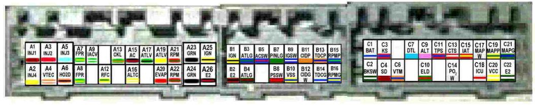
this is D plug.
It�s a 1992 Civic Si I got from the original owner.
I�ve got the passenger side engine harness all layed out cuz some of my connectors I replaced in the past are failing cuz of poor supplies and method. Fresh rebuild and was installing a TB and when checking TPS voltage it�s 6 volts.
Tracing /checking wires and noticed the discrepancy of my harness. 👋🏼
The connector wiring matches Honda Electrical Troubleshooting Manual (ETM) data. Terminal number reference with tab on top; is top left to right then bottom left to right; but, if using the D reference, it is up, down, then across.
Wow, thanks for doing that. I don't think I have that manual pdf. I have the old copies that used to be found, think i may have an Integra ETM...
I've never seen them numbered like that. All the posts on here show the up/down/ across...hmmmm
I'm still a little confused, Thanks for that, man. I've got a lot of matching to do.
I just found a pretty decent copy on ebay, Thanks for this brother!
Now I'm wondering what model the pdf shop manual I have is for......
Top row from left to right are numbered odd... 1,3,5,7, etc. The bottom row from left to right are numbered even... 2,4,6,8, etc. The ECU "D" connector lock clip/tab faces up.
That's what I always thought, But see, it doesn't match what he found 🤷♂️
Yes it does... read Tech8's answer again.
Then, forget the photo and pay closer attention to the wiring data in the list as well as the clip/connector at the bottom of the page.
Yeah I shouldn't have worded it that way, it was rather late...I guess he tried to make it easy for me by numbering conventionally, but I am used to the numbering in the manuals.
What I meant by "doesn't match" was I have been referring to common lists like this one...where the wire colors are different than mine. for example D11 being red/black (it's mint green)
Originally Posted by RACEPAK
hello
hello everyone,
can someone please tell me once and 4 all which diagram is for a p28?
this:
OBD1
A1-INJ1 INJ1 Brown, Battery Voltage with KOEO
A2-INJ4 INJ4 Yellow, Battery Voltage with KOEO
A3-INJ2 INJ2 Red, Battery Voltage with KOEO
A4-VTS VTEC solenoid GRN/YEL, N/a
A5-INJ3 INJ3 Blue, Battery Voltage with KOEO
A6-PO2SHTC O2 sensor (heating element) Org/Wht, Battery Voltage with KOEO
A7-FLR1 fuel pump Grn/BLK, Battery Voltage with KOEO
A8-empty A7 and A8 have the same circurt, so they can be the same
A9-IACV IAC valve Blk/Blu, About 10v KOEO on Warm engine
A10-empty
A11- This is EGR Control Solenoid Valve (if the ECU has) Red, N/A
A12-FANC engine coolant temp switch Blu/red, N/A
A13-MIL MIL (check engine light) Blu/wht, N/A
A14-empty
A15-ACC (a/c compressor clutch) Red/Blu, N/A
A16-ALT C alternator Wht/Grn, N/A
A17-IAB IAB Solenoid Pink, N/A
A18- Org/Red, Transmission Control Module (A/T), N/A
A19- White, Intake control solenoid, Battery Voltage with KOEO
A20-PCS EVAP purge control solenoid Red/Grn, N/a
A21-ICM ICM Yel/Grn, Ignition Control Module (ICM) Output signal, About 10V KOEO
A22- *per Sander* Ignitor same as A21
A23-PG1 ground Black, Power ground, less than 1V
A24-PG2 ground same as A23
A25-IGP2 to main relay and to gound for o Yel/blk, Battery positive from Main relay, Battery Voltage with KOEO
A26-LG1 gound Blk/red, less than 1V
B1-IGP2 to pin A25 Yel/Blk, Battery positive from Main relay, Battery Voltage with KOEO
B2-LG2 ground to shields for CYP & TDC Brown/Blk, Less than 1V
B3- Orange, upshift/downshift comparative input, N/A
B4- Pink, upshift/downshift comparative input, N/A
B5-ACS a/c switch Blu/Blk, A/c input, About 5V with KOEO & A/C off; less than 1V KOER with A/C & blower on
B6-empty
B7- Light green, Park/Neutral switch (A/T), Less than 1V in Park or Neutral with KOEO; 5V in Park or neutral with KOER; Battery voltage in all other positions
B8-PSPSW PSP switch Red/Green, Power steering oil pressure switch, 0V KOEO; Battery Voltage KOER While slowly turning steering wheel
B9-STARTER SIGNAL starter signal Blue/red, Battery Voltage in the START position (clutch depressed on M/T models)
B10-VSS vehicle speed sensor Orange, Pulses 0-12V while turning the left front wheel
B11-CYP P CYP -P Orange, CYP sensor input, N/A
B12-CYP M CYP -M White, CYP sensor signal, N/A
B13-TDC P TDC -P Org/Blue, TDC sensor input, N/A
B14-TDC M TDC -M Wht/Blue, TDC sensor signal, N/A
B15-CKP P CKP -P Blu/Green, CKP Sensor input, N/A
B16-CKP M CKP -M Blu/yel, CKP Sensor signal, N/A
D1-VBU Back Up Power Wht/Yel, Battery positive From battery through Fuse Box, Battery Voltage at ALL times
D2-BKSW brake switch Grn/wht, Battery voltage at all times
D3-KS Knock Sensor Red/Blue, N/A
D4-SCS service check connector Brown/Wht, About 5V (M/T); About 11V (A/T)
D5-empty
D6-VTM VTEC pressure switch Light Blue, N/A
D7-TXD/RXD (data link connector) Light Green/Red, N/A
D8-empty
D9-ALT F alternator Wht/Red, Alternator Charging Signal, About 4.5V KOEO; Decreases under Electrical load (Headlights & rear defogger on) At warm idle
D10-ELD electric load detector input Grn/Blk, N/A
D11-TPS TPS Signal Red/Blk, About 0.5V KOEO with throttle fully closed; About 4.5V KOEO with throttle fully open
D12- Wht/Blk, EGR Valve Lift sensor, About 1.2V KOEO
D13-ECT ECT sensor input Yel/Blu, About 5V KOEO (varies with temperature)
D14-PHO2S O2 sensor White, heated 02 sensor Signal, 0.4-0.5V when ignition is turned on; drops to less than 0.1V within 2 minutes
D15-IAT IAT sensor Red/Yel, Intake Air Temperature signal, .05-4.5V KOEO(Varies with temperature)
D16-VREF VREF shows BLANK on my diagram
D17-MAP Map Signal Wht/Blu, About 3V KOEO (Varies with Temperature)
D18- Light Green/Blk, Transmission Control Module (A/T Only), N/A
D19 - Red/Wht, Reference Voltage, About 5V KOEO
D20 - Yel/Wht, Reference Voltage, About 5V KOEO
D21 - Blue/Wht, Sensor ground, Less than 1V
D22 - Green/Wht, Sensor ground, Less than 1V
OR THIS:
thanks
Found a 1992 specific chart on Scribd and it matches my connectors. In defense of the common lists, D11 STARTS OUT mint green but CHANGES to red/blue (not red/blk) at the sensor..( not mine cuz all the old broken pigtails have been transplanted from newer junkyard cars ) I know that now, after seeing more detailed wire diagrams, but before I found that, I was trying to check continuity from bay to ecu plug and saw my tps was supposed to run to a red/black wire and got suspicious
I guess the creators of some of the lists were trying to tell you which pin position matches the red/yellow wire you're looking at at tps. I was paranoid maybe something else may be different, and I've had enough goose chases on this rebuild.
Thank you very much guys, I'm glad to see some OG gurus were still here to help, AI has been feeding me a ton of wrong answers, and as you know, many threads on here are left unsolved 👋
My Electrical Troubleshooting Manual will arrive soon and I'll have the Gospel.
Sometimes when troubleshooting wiring, people get caught up in the "wire color" part of the wiring diagrams and forget that occasionally, there are multiple colors used for the same wire path in a single generation of a Civic chassis... and as you have discovered, a previous owner may have modified or changed out a connector or two and things just don't seem to match up with the charts you have found in your research. Since you know how to check continuity, focus on wiring positioning: TPS signal should tone cleanly from the center position of the 3-wire plug in the engine bay to D11 at the ECU. Who cares what color the wires are. Attacking it this way will spare you a TON of heartache.
Once you have the FSM, you will have complete wiring diagrams at your fingertips and you will see where wiring changes colors at connectors and when wires are shared between sensors... all will become more clear.


 ) I know that now, after seeing more detailed wire diagrams, but before I found that, I was trying to check continuity from bay to ecu plug and saw my tps was supposed to run to a red/black wire and got suspicious