Honda Accord: How to Swap Automatic for 5-Speed Manual
If you've maxed out your performance mods, try converting your automatic transmission into a five speed manual. This how-to will help you to swap your Honda Accord's automatic transmission with a 5-speed manual.
This article applies to the Honda Accord (1990-2002).
So you have a really nice Honda Accord with an automatic transmission, but it reminds you of the family sedan rather than a sports car. After some cosmetic modifications and some significant performance modifications, is it still not cutting it for you? If you've already done a lot of work in upgrading the the exhaust, headers, and intake modifications, changing your automatic transmission to a 5-speed manual shouldn't be a difficult step up. It could be just the thing you are looking for to finally get a real sporty feel.
Materials Needed
- Metric socket set of various sizes and ratchets
- Flat head and Philips screwdrivers
- Hydraulic floor jacks, jack stands and jack clamps
- Transmission and clutch fluid
- Catch pan
- Dremel tool
- Breaker bar or long pipe for long handled ratchet
- Torque wrench
- JB Weld epoxy
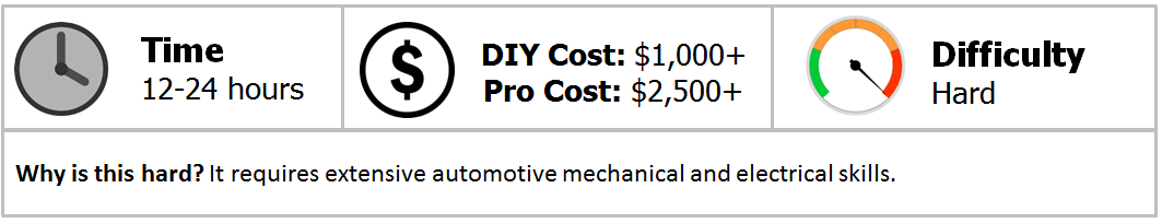
This is not a job for the novice car owner. But if you have already completed fairly complex modifications on your Accord, this is certainly a job you can tackle yourself, saving you from expensive labor costs in the process. If you are not mechanically inclined or are uncomfortable with this big DIY job, consider getting it done by a professional.
Step 1 – Remove the battery and interior
Disconnect the negative terminal (black) of the battery, and then the positive terminal (red). Unscrew the bracket securing the battery to the tray. Remove the battery, and unscrew the tray to remove it as well.
Several components must be removed from the interior, which includes a combination of plastic pop-rivets, Phillips head screws, and some bolts. Begin your removal with the armrest console, the cup holder, and the center console bezel. Remember to keep track of your screws and where it belongs. Remove the steering column plastic cover. Lastly, remove the driver's seat as such:
- Completely slide the seat back.
- Remove the plastic boot-cover at the rear foot of the seat.
- Remove 14mm bolts from the rear brackets.
- Slide the seat forward.
- Remove the plastic boot-cover at the front foot of the seat.
- Remove 14mm bolts from the front brackets.
- Pull it out, and set aside the front seat.

Step 2 – Jack up your car and disconnect ECU
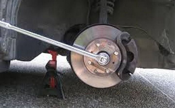
Loosen the lug nuts of your Accord's front wheels. Place the hydraulic floor jacks directly under the front pinch welds of the car. Lift the car, and then set it down on jack stands.
The ECU is located behind the carpeting of the passenger's side kick panel. Unbolt the shield, and remove the ECU.
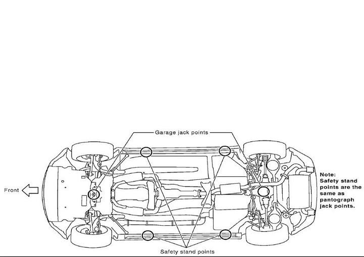
Figure 2. Jack up the front end only. 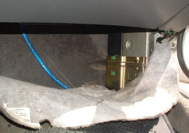
Figure 3. Disconnect and remove ECU from the passenger's side foot well.
(Related Article: How to Jack Up Your Accord - Honda-Tech.com)
Step 3 – Remove the air intake assembly and drain transmission fluid
Use a Phillips screwdriver to remove the hose clamps from both ends of the air intake tube. Pull the intake tube up and out of the engine bay. Then, set it aside.
Slide a catch pan under the drain plug of the automatic transmission oil pan. Unbolt the plug to drain all of the transmission fluid.
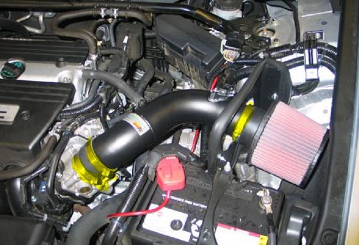
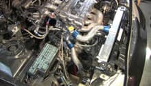
Figure 4. Remove hose clamps (highlighted in yellow) of the air intake assembly. 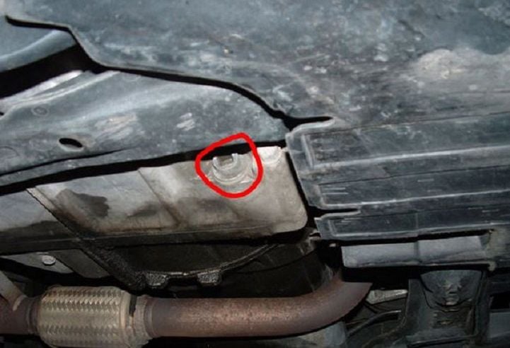
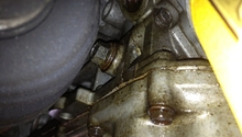
Figure 5. Remove the drain plug (circled in red) from the automatic transmission oil pan.
Step 4 – Remove the wheels and axle nut
Remove the two front wheels. Have a friend step on the brakes, while you remove the axle nut with a socket wrench. The axle nut is torqued very high—about 180 ft lbs. If necessary, use a breaker breaker bar (or an old-fashioned pipe over the handle of your ratchet) to gain extra leverage. Repeat this step on the passenger's side.
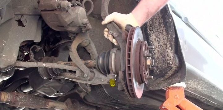
Step 5 – Remove the lower ball joint
Remove the cotter pin and 17mm castle nut of the the lower ball joint. Place the floor jack under the knuckle, and raise it up until the ball joint pops out. Then, remove the axle. Repeat this step on the passenger's side.
Step 6 – Remove axles from the transmission
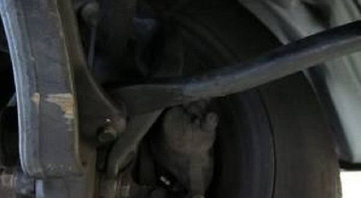
Insert a large flat head screwdriver in between the axle and the transmission to pry them apart. The axle should pop right out. Be sure to keep pressure on both ends of the axles, so the CV joints do not come apart. Pull the axle out the rest of the way. While under the front suspension, unbolt the splash guards on the passenger's side, and remove the radius arm as well. This is the part of the suspension right under the transmission. Do not loosen or damage the bushings or shims.
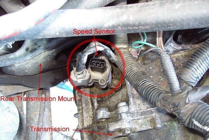
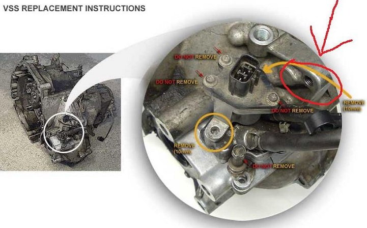
Step 7 – Remove the transmission wire harnesses
Remove all the wire harnesses on and around the transmission (such as the vehicle speed sensor). Set them aside. Do not remove or disconnect any of the vacuum lines.
Step 8 – Remove automatic transmission components
Several parts are not needed for the 5-speed manual transmission. These parts can be removed:
- Remove the shift cable because this will be replaced with the manual cables.
- Remove the torque converter cover.
- Disconnect the transmission hose from the radiator, and reconnect it to the radiator to create a loop.
- Unbolt the catalytic converter heat shield to gain access to the automatic shifter assembly.
Step 9 – Drop the transmission
Gain assistance from a friend as this is one of the more difficult steps. The transmission is very heavy, so great care must be taken to lower it safely. Using the hydraulic jack as a support is a good idea. Place the floor jack in position under the transmission to hold it, and then lower it.
- Place the floor jack under the transmission, and tightly secure it with jack clamps.
- Use your ratchet and socket to remove the eight bolts holding the torque converter to the flex plate. Only one to two bolts can be removed at a time since the transmission crank must be turned to reveal one or two more bolts.
- Maintain pressure with the floor jack, so the transmission doesn't rip out.
- Remove the bell housing bolts from both sides of transmission and engine. This will free the transmission mount. You may have to remove the oil filter to reach all of the bolts.
- Lower and remove the transmission.
- Then, remove the eight 17mm bolts holding the flex plate to the engine block.
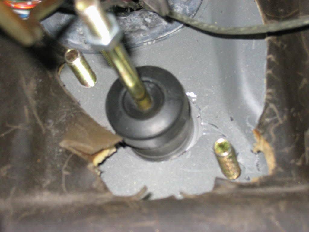
Step 10 – Adjust the transmission mounts
There are two paths to take with this step. The automatic transmission mount is not located in the same location as where the 5-speed transmission mount will be located. Using the same mount will cause undue stress on the axle, which will eventually lead to snapped axles.
The two options are:
- Purchase a 5-speed manual transmission mount from Honda. Cut off the automatic mount weld, and re-weld the manual mount to the correct place on the bracket.
- Drill a new hole in the transmission bracket in the location of the small dimple located above and to the left of the automatic transmission hole.
This step focuses on option #2 as most do not have access to a MIG welder to follow option #1.
Set the manual transmission onto the floor jack, and secure it with jack clamps. Line the transmission straight with the engine; it should be leveled and true where the dimple is located. Mark the location of the dimple on the transmission bracket, and use a six inch, 12mm drill bit do drill in a new hole. This option allows you to use the same rear engine bolts. Even though the 5-speed manual transmission has an extra hole for an extra bolt, it is not necessary to use.
Step 11 – Install the clutch pedal assembly
Drill three holes through the firewall to install the master clutch cylinder mounting studs and the large center plunger. This will require the use of two nuts to install the cabin side mounting studs, which act as spacer. The automatic transmission firewall is flat, so this adjustment must be made. A manual transmission firewall has those spacer nuts pre-mounted and welded to the firewall. You will also need a Dremel tool to clean up the large plunger hole to create a nice fit.
The most important part of this step is to securely bolt and mount the top of the clutch assembly, which is located to the top of the firewall, under the windshield, and behind the wiper motor. This stiffens up the assembly, and prevents the brackets from bending or warping when the clutch pedal is depressed. Lastly, remove the wiper covers. Then, place a 1 to 1.5 inch tube style spacer between the clutch bracket and the top of the firewall. Use lock washers and lock nuts to secure this connection.
Step 12 – Install the new brake pedal
There are two methods to install the new brake assembly. Depending upon which generation Accord brake pedal you use, there will be some slight adjustments that must be made to the replacement brake pedal before you can install it. This step makes use of the 5th generation brake pedal, which requires some minor customization. The 5th generation bracket has the brake switch on the opposite arm. Unfortunately, it cannot be swapped. So you will need to weld or apply a strong adhesive like JB Weld expoxy to fix a piece of metal onto the arm, which touches the switch. While they are touching, the brake lights are off. But when the brake pedal is depressed, that piece of metal is no longer in contact with the switch, and the brake lights come on.
To remove the old brake pedal:
- Remove the cotter pin and bolt.
- Remove the brake master cylinder plunger from the brake pedal.
- Undo the springs, and remove the old brake pedal.
To install the new brake pedal:
- Reattach the spring. Be gentle as it may be difficult.
- Reattach the brake master cylinder plunger to the brake pedal.
- Re-install the bolt with a new cotter pin.
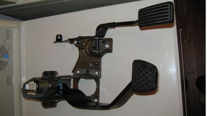
The other method may be much easier:
- Swap the entire accelerator and brake pedal assembly. They are connected to the same bracket.
- The brake switch is already on the correct side, so no welding is necessary.
- Simply install the entire assembly.
Step 13 – Wire the connectors
Install the ECU from a 5-speed manual Accord. Also, use the same OBD-I or OBD-II in the swap; otherwise, you will need to rewire the harness. If you switched from OBD-II to OBD-I, convert the following wire colors:
- OBD-I orange/blue wire to yellow, white/blue wire to black (wire located on top of the distributor).
- OBD-I orange wire to red, white wire to green, blue/yellow wire to white, blue/green wire to blue (wire located down by the crank pulley).
- The crank pulley's orange and white wires are for the TDC sensor. The blue/yellow and blue/green wires are for the crank position sensor.
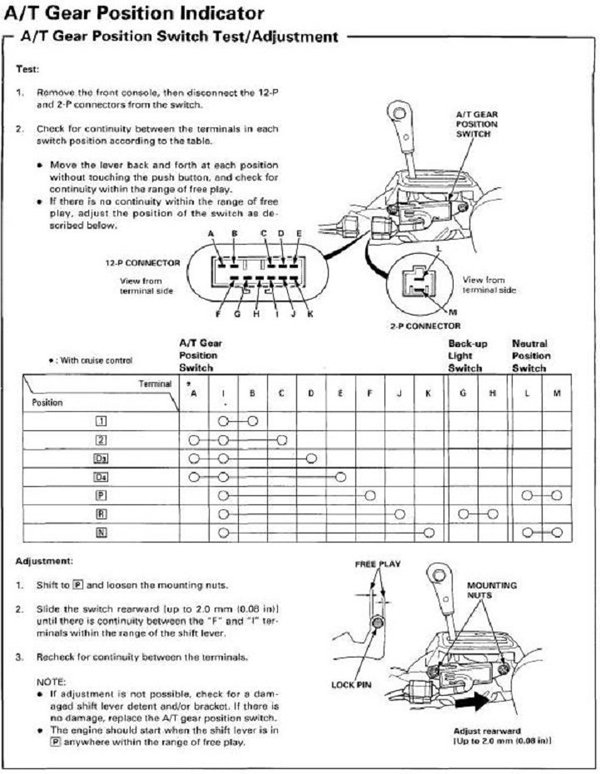
The reverse, ignition, and key removal lights go with the shifter assembly:
- Remove the remaining bolts of the shifter assembly, and detach all of the wiring harnesses as well as connectors.
- The automatic shift cable disconnected (in Step 8) routes through a hole in the center console. Remove the cable.
- In the driver's side of the shifter assembly is a white clip on a slider. Place the shifter into the "Park" position.
- Unscrew the white shift selector from the assembly.
- Follow the diagram (Figure 13) below to rewire the shift selector.
- The clutch safety switch connects to L and M terminals.
- The reverse switch connects to the G and H terminals.
- Connect the F and I terminals for the key removal switch.
- Reconnect the remaining wire harnesses, and move them all into the center console.
Step 14 – Reassemble the transmission
- Bolt the new flywheel with its supplied bolts as the others are too short. Torque them to their proper specs.
- Have your friend depress the clutch pedal, and use the alignment tool to line the pedal properly with the flywheel.
- Torque the pressure plate bolts to their proper specs.
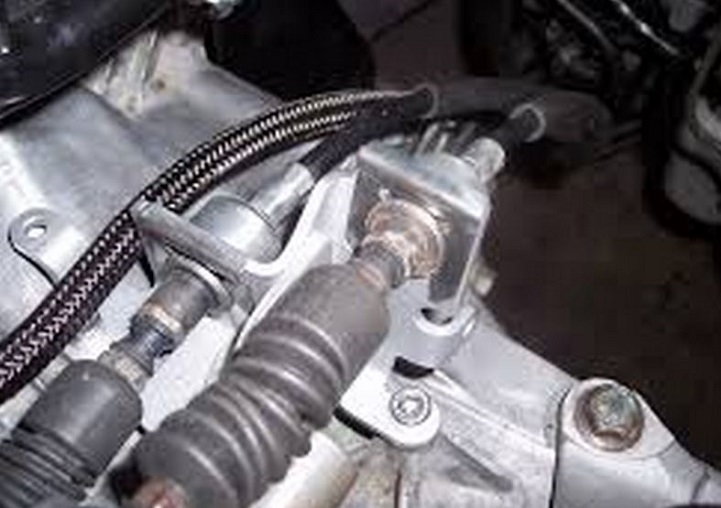
- Bolt the clutch slave cylinder and the shift linkage bracket to the transmission.
- Make sure the VSS and the reverse sensors are both near the front of the transmission.
- Route the clutch hard line from the clutch master cylinder to the dampener. Then, route it to a rubber line connected the banjo bolt. Continue to route the wire to another hard line of the transmission, and to the slave cylinder.
- Jack up your transmissions, and shimmy it into place. Make sure it lines up perfectly with the engine.
- Get it as flush as possible, and secure all the bolts connecting the engine to the transmission. Make sure to secure the bolt behind the oil filter, and replace the oil filter after the installation.
- Once the transmission is up and bolted on, screw in the clutch line to the slave cylinder.
- Attach the intermediate shaft to the transmission with the three supplied bolts.
- Plug the VSS back in.
- Wire the reverse switch to the wires from the shift selector, which are located inside of the center console.
Step 15 – Install the new cables
- Push your new cables through the same hole(s) where the automatic transmission cables snaked through.
- Bolt down the shifter assembly.
- Re-install the two 10mm bolts behind the heat shield.
- Route the cables from over the rear mount and under the intake manifold. Then, route the cables through the shifter linkage bracket.
- Attach two "C" clips to notches in the cable to secure it to the bracket.
Step 16 – Re-install the assembly
- Bolt on the 5-speed starter. Attach the ground and positive cables of the starter to the long bolt that passes through the starter, transmission, and into the engine.
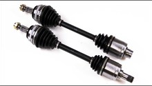
- Replace the passenger's side axle pushing into the transmission, so there are no gear splines showing.
- Replace the ball joint and knuckle assembly.
- Re-install the radius arm. Reassemble the bushings, shims, and washers on the cross-member.
- Torque the radius arm nut to its proper specs.
- Install the new driver's side axle into the intermediate shaft, and into the hub.
- Re-install the ball joint and knuckle assembly.
- Replace the lower splash guards.
- Re-install the flywheel cover plate.
- Re-install the battery tray, and the battery.
- Reconnect all of the wiring harnesses near and around the distributor (three connections).
- Double check your timing if you have switched from OBD-I to OBD-II, or vice versa.
- Have your friend hit hard on the brakes, while you torque the axle nuts back down to 180 ft lbs.
- Replace the wheels, lower the wheels, and torque all of the lug nuts to their proper specs.
Step 17 – Complete the installation
- Bleed the clutch line, and add new manual transmission fluid.
- Start the car, and let it idle for approximately 15 minutes, so the ECU can properly reset. Make sure not to rev the engine.
- Adjust the travel path of the brake, and clutch pedals by turning the bolt on the U-joint or the plunger nut.
- Re-install the driver's seat and interior.
Related Discussions
- Auto to 5-Speed Swap - Honda-Tech.com
- Auto to 5-Speed Write-Up - Honda-Tech.com