
DIY How-to: Calibrating the Voltage on your TPS Sensor
 01-25-2014, 10:22 AM
#26
Honda-Tech Member
Join Date: Mar 2005
Location: Seattle, WA
Posts: 1,260
Likes: 0
Received 0 Likes
on
0 Posts
Hey guys I got a 95 ls motor from the junk yard to run in my 95 hatch I had a gsr but spun a bearing so now I'm in the process of fully building that up. The tps on the ls took a s*** on me so I pulled the tps from the gsr and as I am calibrating it on the ls I set it to 4.5v at wide open throttle but when I check it at close throttle its reading .77v. So I checked all wires to make sure they are reading what they should and everything's correct. Any body have this problem or no how to fix it? Thanks
Also, test the resistance between the power and ground while slowly turning the bottom of the TPS. If the TPS resistance jumps or falls off then you possibly have a bad TPS.
 02-12-2014, 12:36 AM
#27
Honda-Tech Member

Join Date: Feb 2014
Posts: 16
Likes: 0
Received 0 Likes
on
0 Posts
NOTE: You can remove the original "rivet screws" by simply grinding a slot across the center like a flathead screw, then unscrew them like normal screws. Much faster and easier. I found some large-base 8mm hex bolts (M6 thread size, unknown pitch) which fit perfectly, I think they were randomly off some VW. But if you chop your slots in the original rivet screws well enough you can just reuse the originals, too.
On the stop screw setting, if you've removed and reinstalled the throttle plate for cleaning then you have to reset it, ignore the "factory knows all" warnings in that case. Crank it out until the TPS stops dropping in volts, then crank it back in until it jumps up 0.01 or 0.02 (meaning you're at the factory "anti-slam" throttle stop because the shaft just began to move, and it then won't chew up your bore or have sticky closed throttle). Mine happened to be 0.67v at closed when 4.51v at WOT, so if I didn't fiddle the stop setting I would have to choose between loss of the idle features (decel fuel cut, etc) or bad WOT shifting (slippy 1st). IF after you set the throttle stop to "barely open" then set the 0.48v, you can't reach 4.5v then bend (or file, depending how far you need to go) the WOT stop tang as described.
KOEO or KOEO+charger have no effect on the TPS voltage. The 5v reference regulator must be a pretty good one unaffected by the overall system voltage. VW's require a charger boost hooked up during their TPS/MAF calibration routine so that the system is at "running voltage" (not less than 12.5v). But they also have drive by wire so it's likely more sensitive.
Last edited by Spudz76; 02-12-2014 at 01:47 AM.
03-04-2014, 07:18 PM
#28
Honda-Tech Member
back from the dead. hopefully someone can assist me with this I originally did my calibration using the body of the car as the ground. and pwr probe the red wire with blue stripe. obviously bot incorrect reading 3.50 at idle. Should i have gotten a closer reading to .45 or i definately cannot use the ground of the car? ps my harness is obd 0 red w/ blue stripe....yellow w/ white stripe.....green w/ yellow stripe. Should i redo the test with the red blue stripe(positive) and green with yellow stripe (negative). thanks in advance

 06-01-2014, 05:50 PM
#30
Honda-Tech Member
Thread Starter
Join Date: Oct 2010
Location: Byron Bay Australia
Posts: 98
Likes: 0
Received 0 Likes
on
0 Posts
back from the dead. hopefully someone can assist me with this I originally did my calibration using the body of the car as the ground. and pwr probe the red wire with blue stripe. obviously bot incorrect reading 3.50 at idle. Should i have gotten a closer reading to .45 or i definately cannot use the ground of the car? ps my harness is obd 0 red w/ blue stripe....yellow w/ white stripe.....green w/ yellow stripe. Should i redo the test with the red blue stripe(positive) and green with yellow stripe (negative). thanks in advance
Remember U can test the wires at the ECU end to make sure the wires aren't faulty and sending incorrect signals to the ECU.
I watched the vid with no audio but How does the car idle and drive?
I'm no pro but I'm thinking to try another tps and/or check the voltages at the ECU end just to see if it's the same,therefore the wires are consistent but I don't think that will verify they are ok/undamaged.
Can anyone else chime in on this? (I'm not online much anymore..)
Does anyone else's do this? I will have to see if mine is like this out of interest.
Good luck with it mate and I'll check in when possible.
WOW,I'm quite proud of this thread to be honest after seeing how many views it's getting.
This came about after having little niggling issues with my engine like surging/hesitation etc and a strong will to learn what the problems are and fix them,therefore having the engine running at it's best.It took a lot of determination and patience and it's just so great to be able to share the effort and U guys all round the world benefit.I've certainly learnt a lot from others who share the knowledge
 08-01-2014, 07:28 PM
#31
To the author: thank you!!!
I used your writeup to adjust the TPS in my 2000 CRV. It fixed a high idle and shift interlock issue. Very good directions which gave me a lot of confidence as I jumped into the project.
I used your writeup to adjust the TPS in my 2000 CRV. It fixed a high idle and shift interlock issue. Very good directions which gave me a lot of confidence as I jumped into the project.
09-16-2014, 01:50 AM
#32
Honda-Tech Member

Join Date: Sep 2014
Posts: 2
Likes: 0
Received 0 Likes
on
0 Posts
I just wondering how come it doesn't work to my odyssey (RB1 engine) instead of that i can not move the gear from P. Then When i check by OBD II TPS show/read 79%.
So i decrease to 47% (move TPS) and gear back to normal.
Any idea ?
So i decrease to 47% (move TPS) and gear back to normal.
Any idea ?
Aim:
To calibrate the voltage on the TPS Sensor,a sensor on the throttle body that tells the ECU where the throttle is positioned.Over time the Tps goes out of calibration and your car's performance suffers greatly for it.
I was VERY impressed with the difference this made to my car.It increased throttle response,smoothly revving across the whole rev range and makes for a far enjoyable car to drive.
If your car is around the 8 year old mark,you should DEFINATELY do this if you want better performance from your car and offcoarse,who dosen't?!
Again,I can't emphasize how effective this is,a must do!
Combined with modifying ya stock TB,your car won't be the same and you'll NEVER wanna go back to stock again!
So do em' both eh!
Modifying the stock TB for more airflow
EK1 Civic has just done this,this is what he said after it:
THE TPS IS OVERLOOKED OR SHOULD I SAY NOT UNDERSTOOD BUT THE TPS HOLDS GREAT BENEFITS WHEN CALIBRATED.
Required:
Hacksaw
Suburu Upper Engine Cleaner/Super Engine Conditioner
Screwdrivers
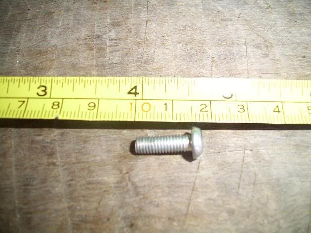
2 screws 16mm x 5mm Metric thread with a dome head
2 pins
Multimeter
Allen Key (maybe needed for the Throttle stop screw)
Small socket and ratchet
This can be performed by yourself,without help,no problem.
This is being done on a d16y4.
The screws you need are 16mm long and 5mm wide,metric thread,with a dome head.Definately both d and b series engines use this screw.
16x5 Metric thread with a dome head:
Steps:
Remove the Throttle body -
4 bolts
3 sensors that just unplug (TPS,Map and IACV)
2 coolant hoses on the bottom,unclip the metal clamp and pull the hose off.A little coolant will run out,perfectly fine.If you don't want to loose the coolant,plug the hoses up.
Accelerator cable (and gearbox cable if an automatic)
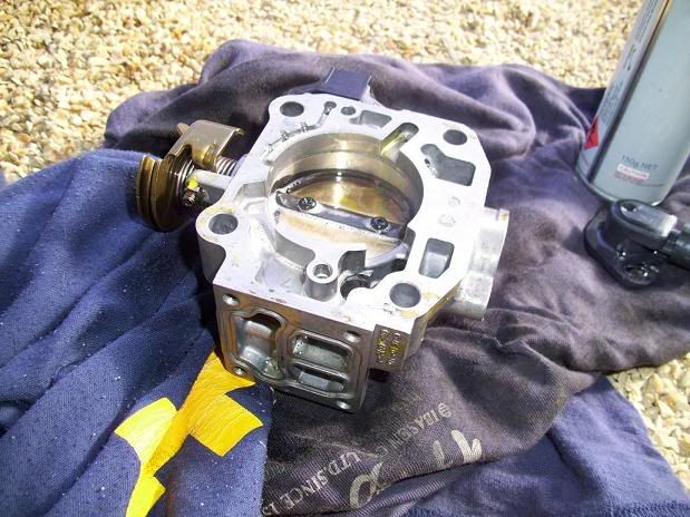
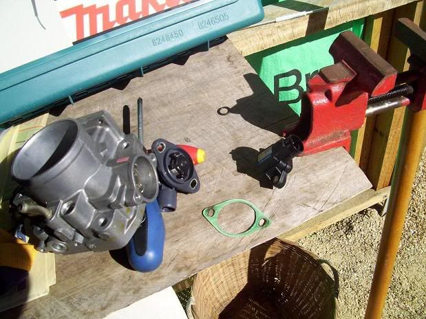
Give it a clean:
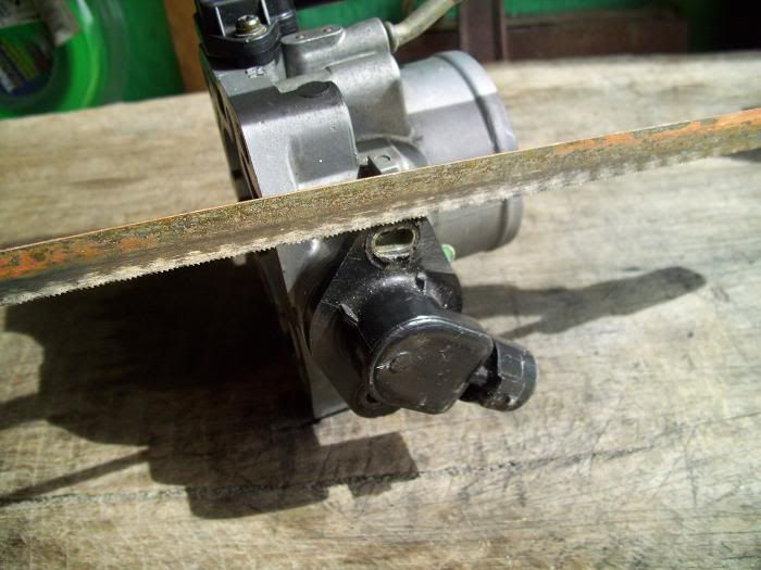
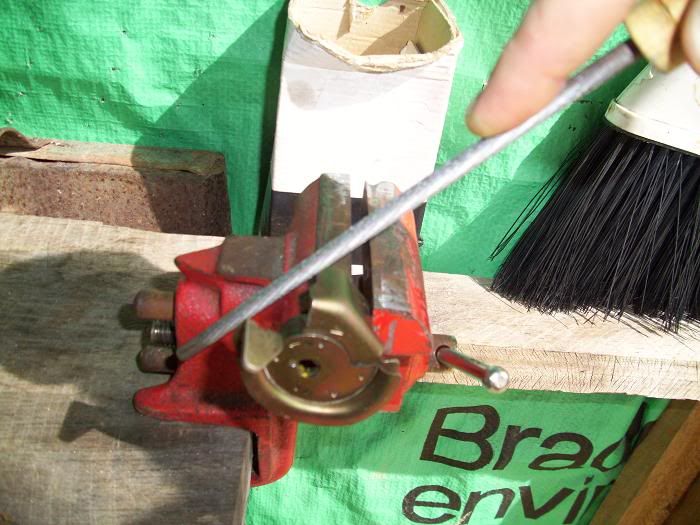
If your tps is riveted on,U can hacksaw them off,dont need a grinder:
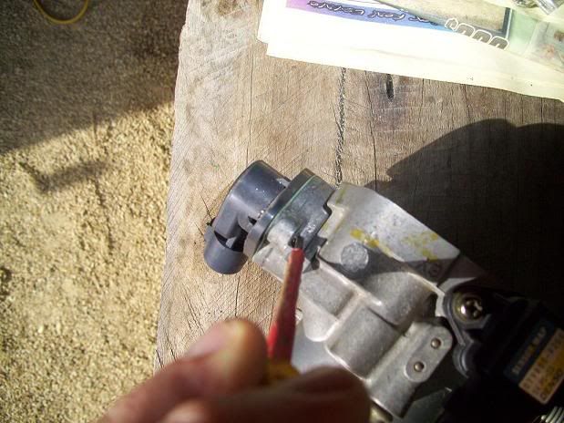
Use a screwdriver to tap the thread left in there out:
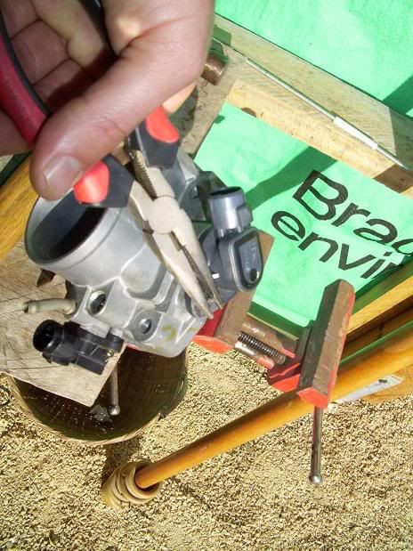
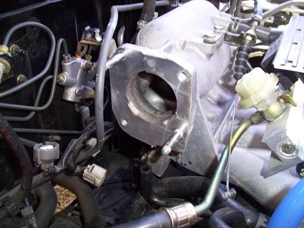
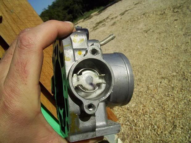
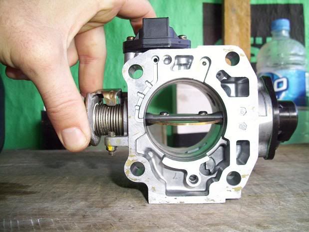
There She blows!
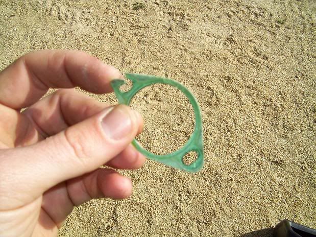
The Tps gasket is torn but it wont matter at all,so I will re-use it:
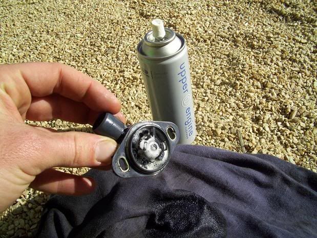
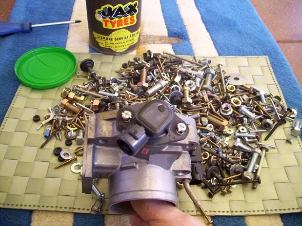
Now,clean the whole Throttle body up,I only use Suburu Upper engine cleaner to clean with now OR another product which I reckon is subi upper engine cleaner in another bottle is 'Engine conditioner',it's a Japanese product,i.e Japanese writing on the bottle and it's brilliant.Carby cleaner is crap.
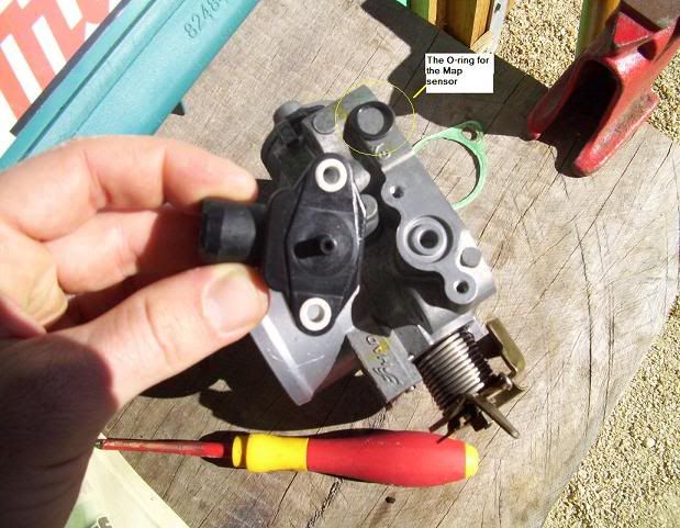
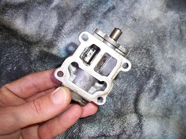
Map Sensor:
Intake Air Control Valve (IACV),Clean that up real good!
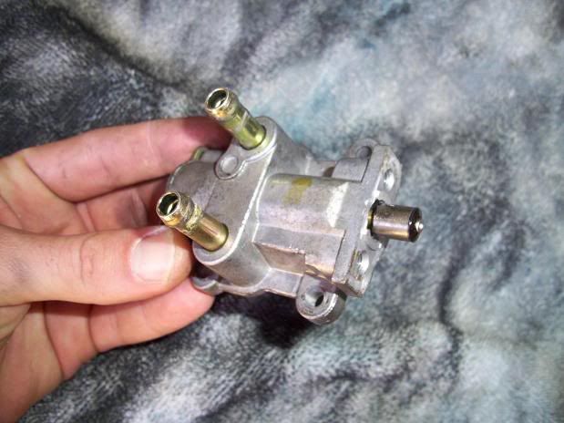
Let it all dry out:
Time to get them screws!
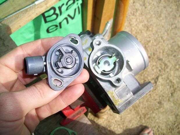
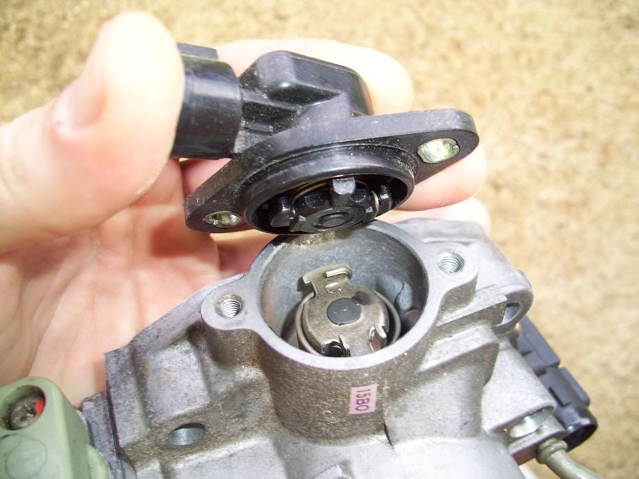
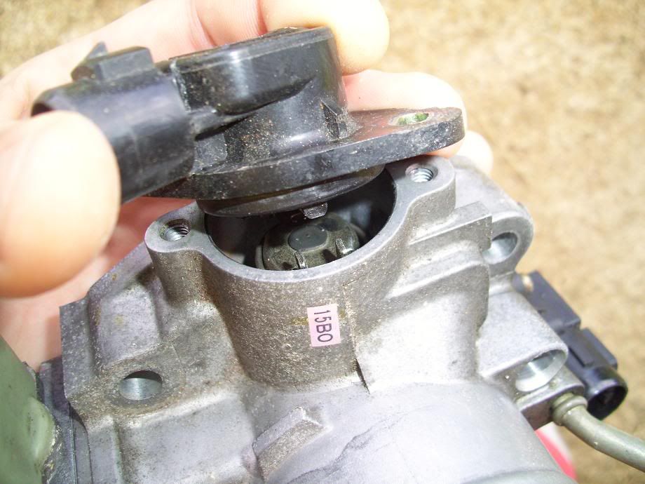
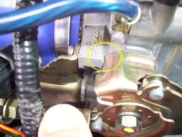
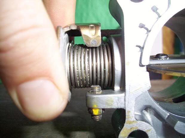
IMPORTANT: When U put it back together,make sure that little plastic doova on the tps goes between those 2 metal bits.
Put it all back together:
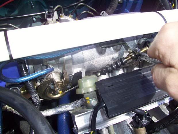
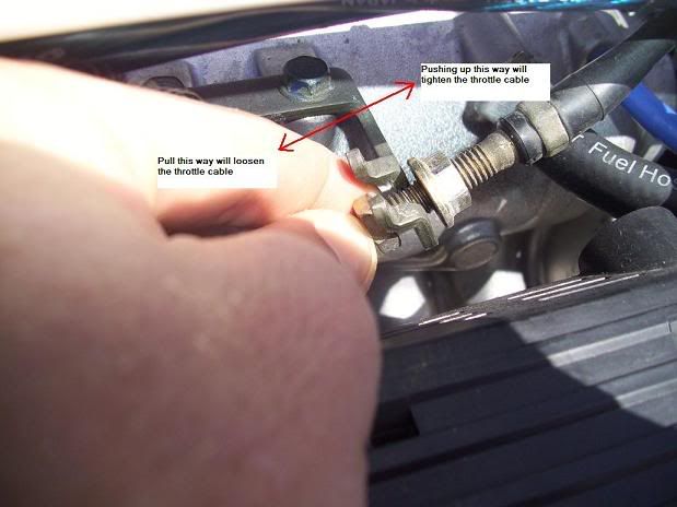
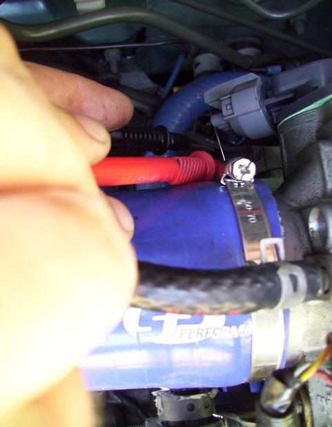
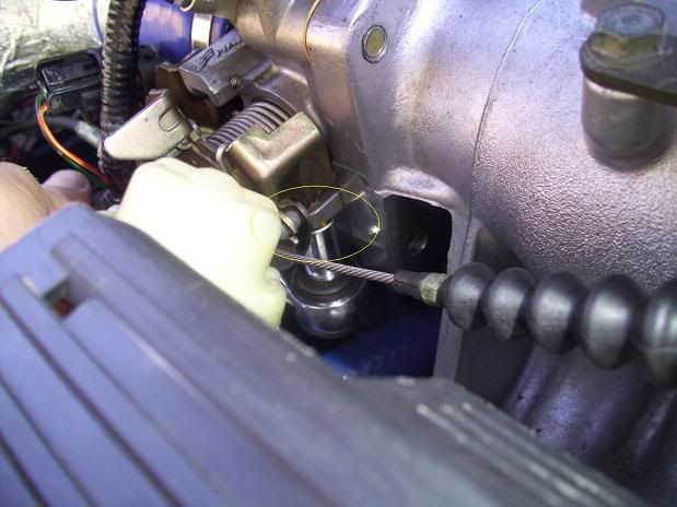
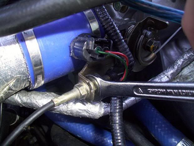
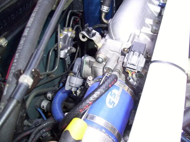
Next,is to adjust the throttle cable..This is done by undoing these 2 nuts and tensioning the cable:
At Closed Throttle (CT) the cable needs to be firm but not tight.At Wide Open Throttle (WOT) when the pedal hits the floor should be the same time as the Throttle body Wide Open Throttle stop (WOT) is contacted,therefore there is no significant load on the cable nor the WOT stop:
The WOT stop varies in design but the exact same principle.I know on the b18c it's on the bottom.
The easiest way to achieve this is to put your foot to the floor (WOT) and check the above.If there is a gap,the cable needs to be tensioned to close the gap.If the TB WOT stop is contacted before the pedal hits the floor,you need to loosen the cable off a bit.
Here's a VIDEO of the end result.A nice firm cable.When the accelerator pedal makes contact with the floor,is the same time the TB WOT stop is contacted,Beautiful!:
OK.Now the fun part.On the TPS sensor,there are 3 wires - Yellow,red and green (all with a black stripe)
Red is Positive and Green is Negative.
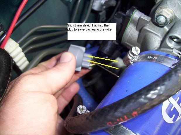
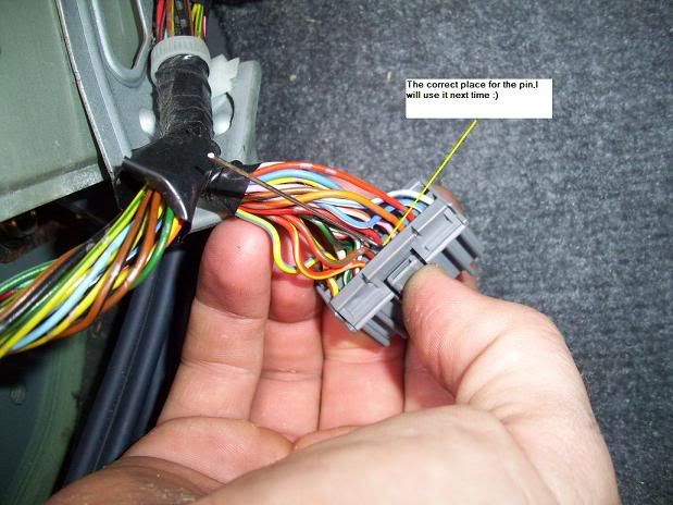
I inserted the pin through the wire but I have learnt that the better way to save damaging the wire is to stick the pin up into the plug where the wire connects to the plug,as so:
Now,turn the car keys turned to the second click,so the lights on the dash come on.Then perform these tasks -
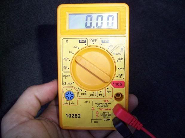
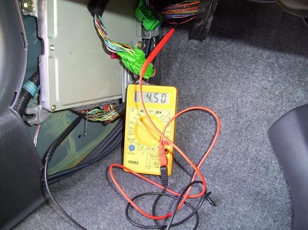
Set your multi meter to volts.We are looking for a range of 0-5 Volts,so the 20V setting is best:
Positive probe to positive wire and negative probe to negative wire:
Note: You can wedge the probes under something to stay on the pins,without the need to hold them.This will allow you to do this by your self.
[B]THESE VOLTAGES ARE THE SAME FOR ALL HONDA'S
0.48V @ CT (Closed Throttle)
4.5V @ WOT (Wide Open Throttle)
Now,hold the Throttle plate at WOT:
And turn the TPS until you get 4.5V on the multi meter:
Then tighten it back down:
Re-check the setting haven't changed after tightening the TPS.
After you have done that,check the voltage at CT (Closed Throttle).This is where the TS screw (Throttle stop) will need to be adjusted to set the CT Voltage.
If you have a value greater than 0.48V,you will need to wind the TS screw out to open/increase the voltage range.If it's less,wind it in/up to close the gap/range.
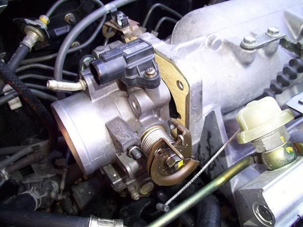
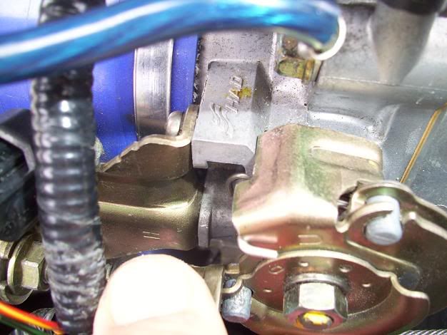
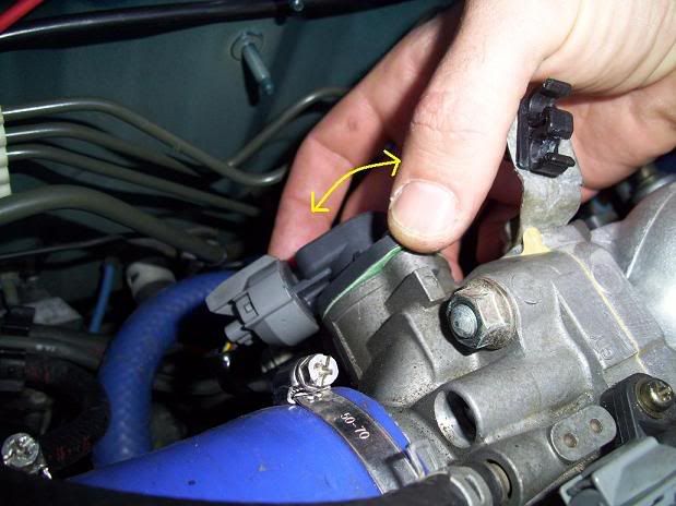
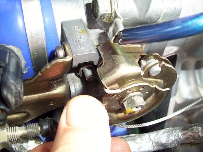
Throttle Stop screw on the d16y4,from behind:
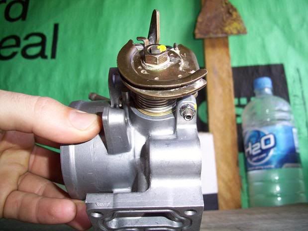
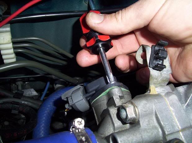
Adjust it like this with an Allen key:
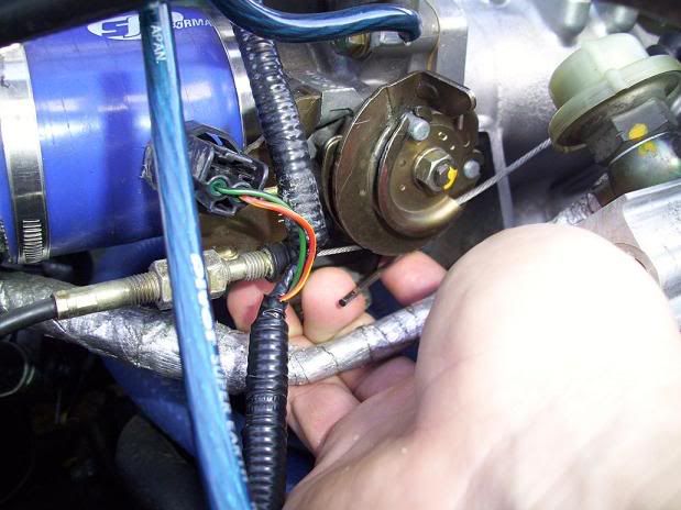
Under here:
Firstly you will need to undo the nut on there to be able to turn the screw.Make sure the nut is tightened up when you set the values.
Undo/tighten the TS screw until you get a 0.48V Value for CT.
TIP: When you tighten the nut up with the ratchet,the voltage will increase slightly by 0.01V-0.02V.So,adjust the TS screw with the allen key to 0.46V-0.47V value and tighten the nut up good with your ratchet.This way you will get the required 0.48V and a tight nut on the TS screw!
Now,re-check the WOT value.I bet it has moved? It maybe at 4.52 for example.So CT is at 0.48 and WOT at 4.52,so the range is 0.02 too much.So we need to close the range in by 0.02.Do this via the TS screw.Turn it up to 0.50.Then set WOT again at 4.5V by turning the TPS until you see this value,tighten it back down.CT should now be 0.48V and WOT at 4.5V.
VIDEO:
This is the final result,a perfectly set up accelerator pedal and Throttle body,performing at it's best!
You can hear CT and WOT stop's being contacted.The pedal feels perfect.At the same time the pedal is contacting with the floor,the WOT stop is being contacted on the Throttle body.At CT there is no significant 'load' on the pedal but there is tension in the cable,keeping the pedal firm with no free play.Perfect.
Between the TS screw,moving the TPS and the tensioning the accelerator cable and a bit of patience,this can be achieved.
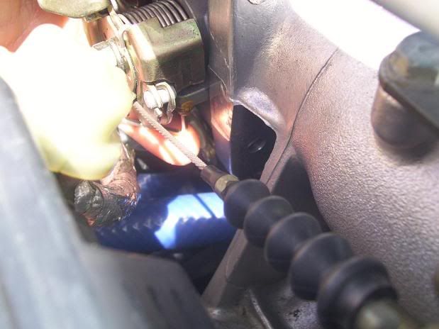
Note: If your car is an automatic and you cant get both value's,your gearbox cable maybe too tight and restricting movement,like mine was.I could get 0.48V but Wide Open Throttle was 4.33V.I loosened off the gearbox cable and I could get 0.48V and 4.5V easily.The cable was restricting movement.
You will need to loosen off the cable to free up some movement,it's the same set up as the accelerator cable:
If your automatic 'kicks' into gear,like too much then your gearbox cable is too tight,Loosen it off.
Also,be wary your carpet under the accelerator pedal may be restricting the pedal and may need to be removed like mine did to get a better pedal.
If U get WOT,4.5V and can only get say 0.52V for CT.This means U need to increase the range at which the throttle plate moves by 0.04V.To do this U can simply file a small amount off the throttle rotor,like this:
Then set the WOT again first,then the CT,done!
After your done,set the idle via the idle air adjust screw.
Make sure the car is fully warmed up and simply turn the screw until the idle is where you want it.For a manual car,set the idle when the car is in neutral and for a automatic car,set the idle with the car in 'D'.It's 'D' that you will be sitting in at lights,so that's where you want to set it,not Park,'P'.
When you reset the ECU it will even the idle out.
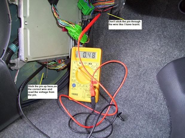
Now we need to check that the values are the same at the ECU end.This will ensure the wires are fine and the ECU is seeing the same readings.
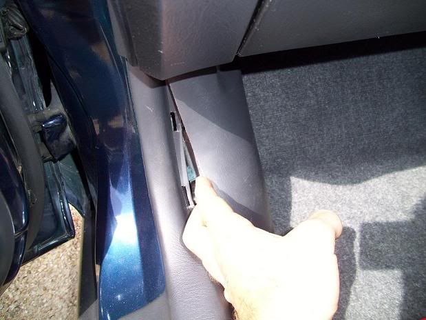
Remove the kick panel at the passengers feet to expose the ECU and wiring,1 clip and a bolt (How cool is the big march fly in the shot!):
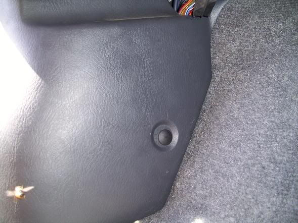
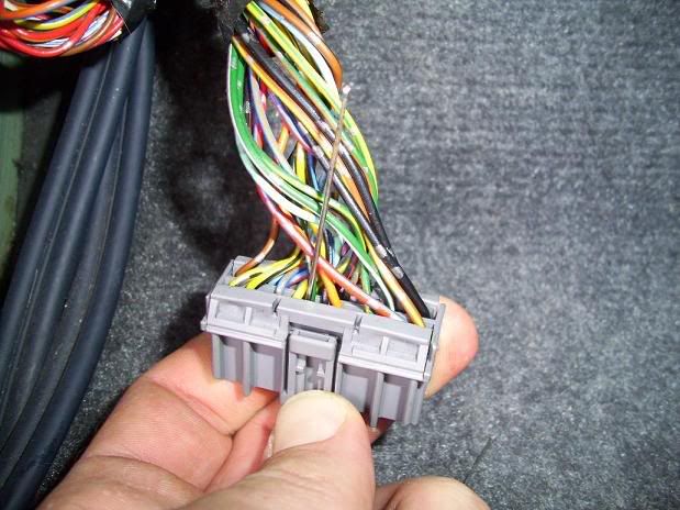
Don't stab and ruin the wires like I did,stick the pins up into the connector,like this:
Closed Throttle:
Wide Open Throttle (WOT):
Also:
* Probe the Yellow and green wires to verify that you have 5v going to the TPS.
* Check the reading starts at 0.48V and smoothly increase to 4.5V,showing you have nice smooth throttle increase/decrease coming from the TPS to the ECU.This will verify the wiring between the TPS and ECU is fine.
VIDEO:
After you have completed that Reset the ECU and bleed the air from your coolant lines.This can be done by parking your car on a hill so that the engine is the high point,this will allow the air to escape easier.Start the car up,pop the hood and undo the radiator cap,take it right off so you can watch the air escaping.Just let it idle for a few minutes (at least the fan comes on twice).Give the coolant hoses a squeeze to help the air escape.
Your car will run better with no air in the coolant system.
NOTE: If U experience a high idle that goes up to 2,000rpm and then drops off and keeps repeating this (as discussed on page 8),chances are the Throttle plate is a bit open and needs closing.First try screwing in the idle/air screw on the top,if that dosen't do the job,probably won't,you will need to screw the TS screw out to close the throttle plate.The CT voltage will read 0.44V or so when the idle stabilizes but don't worry it shouldn't affect the performance of the car as I am learning).
IF the idle persists to be erratic,i.e. quite bad then look to fix the problem via the FITV - You-Have-Cleaned-the-IACV-BUT-Your-Idle-Is-Still-High-Erratic-Adjust-The-FITV.
Here is another GREAT DIY U can do aswell! Modifying-the-stock-Throttle-body-for-more-air-flow
Enjoyz!
Still doubt how effective this is?
This is quoted from JohnL Ozhonda's very own resident Suspension Expert! (Taken from this thread):
And....wait for it....
I set CT to 0.51V and WOT at 4.53V for a week then put it back to 0.48 - BIG DIFFERENCE!
For Everything that I have ever learnt about Cars/honda's,this is by far the most important and effective.I wish everyone had this done already.Our Honda's would be tearing up the planet!
So skip the Hot chicks thread tonight for a change,read this a few times,get confident with it and....DO IT! :thumbsup:
:honda:
To calibrate the voltage on the TPS Sensor,a sensor on the throttle body that tells the ECU where the throttle is positioned.Over time the Tps goes out of calibration and your car's performance suffers greatly for it.
I was VERY impressed with the difference this made to my car.It increased throttle response,smoothly revving across the whole rev range and makes for a far enjoyable car to drive.
If your car is around the 8 year old mark,you should DEFINATELY do this if you want better performance from your car and offcoarse,who dosen't?!
Again,I can't emphasize how effective this is,a must do!
Combined with modifying ya stock TB,your car won't be the same and you'll NEVER wanna go back to stock again!
So do em' both eh!
Modifying the stock TB for more airflow
EK1 Civic has just done this,this is what he said after it:
THE TPS IS OVERLOOKED OR SHOULD I SAY NOT UNDERSTOOD BUT THE TPS HOLDS GREAT BENEFITS WHEN CALIBRATED.
Required:
Hacksaw
Suburu Upper Engine Cleaner/Super Engine Conditioner
Screwdrivers
2 screws 16mm x 5mm Metric thread with a dome head
2 pins
Multimeter
Allen Key (maybe needed for the Throttle stop screw)
Small socket and ratchet
This can be performed by yourself,without help,no problem.
This is being done on a d16y4.
The screws you need are 16mm long and 5mm wide,metric thread,with a dome head.Definately both d and b series engines use this screw.
16x5 Metric thread with a dome head:
Steps:
Remove the Throttle body -
4 bolts
3 sensors that just unplug (TPS,Map and IACV)
2 coolant hoses on the bottom,unclip the metal clamp and pull the hose off.A little coolant will run out,perfectly fine.If you don't want to loose the coolant,plug the hoses up.
Accelerator cable (and gearbox cable if an automatic)
Give it a clean:
If your tps is riveted on,U can hacksaw them off,dont need a grinder:
Use a screwdriver to tap the thread left in there out:
There She blows!
The Tps gasket is torn but it wont matter at all,so I will re-use it:
Now,clean the whole Throttle body up,I only use Suburu Upper engine cleaner to clean with now OR another product which I reckon is subi upper engine cleaner in another bottle is 'Engine conditioner',it's a Japanese product,i.e Japanese writing on the bottle and it's brilliant.Carby cleaner is crap.
Map Sensor:
Intake Air Control Valve (IACV),Clean that up real good!
Let it all dry out:
Time to get them screws!
IMPORTANT: When U put it back together,make sure that little plastic doova on the tps goes between those 2 metal bits.
Put it all back together:
Next,is to adjust the throttle cable..This is done by undoing these 2 nuts and tensioning the cable:
At Closed Throttle (CT) the cable needs to be firm but not tight.At Wide Open Throttle (WOT) when the pedal hits the floor should be the same time as the Throttle body Wide Open Throttle stop (WOT) is contacted,therefore there is no significant load on the cable nor the WOT stop:
The WOT stop varies in design but the exact same principle.I know on the b18c it's on the bottom.
The easiest way to achieve this is to put your foot to the floor (WOT) and check the above.If there is a gap,the cable needs to be tensioned to close the gap.If the TB WOT stop is contacted before the pedal hits the floor,you need to loosen the cable off a bit.
Here's a VIDEO of the end result.A nice firm cable.When the accelerator pedal makes contact with the floor,is the same time the TB WOT stop is contacted,Beautiful!:
OK.Now the fun part.On the TPS sensor,there are 3 wires - Yellow,red and green (all with a black stripe)
Red is Positive and Green is Negative.
I inserted the pin through the wire but I have learnt that the better way to save damaging the wire is to stick the pin up into the plug where the wire connects to the plug,as so:
Now,turn the car keys turned to the second click,so the lights on the dash come on.Then perform these tasks -
Set your multi meter to volts.We are looking for a range of 0-5 Volts,so the 20V setting is best:
Positive probe to positive wire and negative probe to negative wire:
Note: You can wedge the probes under something to stay on the pins,without the need to hold them.This will allow you to do this by your self.
[B]THESE VOLTAGES ARE THE SAME FOR ALL HONDA'S
0.48V @ CT (Closed Throttle)
4.5V @ WOT (Wide Open Throttle)
Now,hold the Throttle plate at WOT:
And turn the TPS until you get 4.5V on the multi meter:
Then tighten it back down:
Re-check the setting haven't changed after tightening the TPS.
After you have done that,check the voltage at CT (Closed Throttle).This is where the TS screw (Throttle stop) will need to be adjusted to set the CT Voltage.
If you have a value greater than 0.48V,you will need to wind the TS screw out to open/increase the voltage range.If it's less,wind it in/up to close the gap/range.
Throttle Stop screw on the d16y4,from behind:
Adjust it like this with an Allen key:
Under here:
Firstly you will need to undo the nut on there to be able to turn the screw.Make sure the nut is tightened up when you set the values.
Undo/tighten the TS screw until you get a 0.48V Value for CT.
TIP: When you tighten the nut up with the ratchet,the voltage will increase slightly by 0.01V-0.02V.So,adjust the TS screw with the allen key to 0.46V-0.47V value and tighten the nut up good with your ratchet.This way you will get the required 0.48V and a tight nut on the TS screw!
Now,re-check the WOT value.I bet it has moved? It maybe at 4.52 for example.So CT is at 0.48 and WOT at 4.52,so the range is 0.02 too much.So we need to close the range in by 0.02.Do this via the TS screw.Turn it up to 0.50.Then set WOT again at 4.5V by turning the TPS until you see this value,tighten it back down.CT should now be 0.48V and WOT at 4.5V.
VIDEO:
This is the final result,a perfectly set up accelerator pedal and Throttle body,performing at it's best!
You can hear CT and WOT stop's being contacted.The pedal feels perfect.At the same time the pedal is contacting with the floor,the WOT stop is being contacted on the Throttle body.At CT there is no significant 'load' on the pedal but there is tension in the cable,keeping the pedal firm with no free play.Perfect.
Between the TS screw,moving the TPS and the tensioning the accelerator cable and a bit of patience,this can be achieved.
Note: If your car is an automatic and you cant get both value's,your gearbox cable maybe too tight and restricting movement,like mine was.I could get 0.48V but Wide Open Throttle was 4.33V.I loosened off the gearbox cable and I could get 0.48V and 4.5V easily.The cable was restricting movement.
You will need to loosen off the cable to free up some movement,it's the same set up as the accelerator cable:
If your automatic 'kicks' into gear,like too much then your gearbox cable is too tight,Loosen it off.
Also,be wary your carpet under the accelerator pedal may be restricting the pedal and may need to be removed like mine did to get a better pedal.
If U get WOT,4.5V and can only get say 0.52V for CT.This means U need to increase the range at which the throttle plate moves by 0.04V.To do this U can simply file a small amount off the throttle rotor,like this:
Then set the WOT again first,then the CT,done!
After your done,set the idle via the idle air adjust screw.
Make sure the car is fully warmed up and simply turn the screw until the idle is where you want it.For a manual car,set the idle when the car is in neutral and for a automatic car,set the idle with the car in 'D'.It's 'D' that you will be sitting in at lights,so that's where you want to set it,not Park,'P'.
When you reset the ECU it will even the idle out.
Now we need to check that the values are the same at the ECU end.This will ensure the wires are fine and the ECU is seeing the same readings.
Remove the kick panel at the passengers feet to expose the ECU and wiring,1 clip and a bolt (How cool is the big march fly in the shot!):
Don't stab and ruin the wires like I did,stick the pins up into the connector,like this:
Closed Throttle:
Wide Open Throttle (WOT):
Also:
* Probe the Yellow and green wires to verify that you have 5v going to the TPS.
* Check the reading starts at 0.48V and smoothly increase to 4.5V,showing you have nice smooth throttle increase/decrease coming from the TPS to the ECU.This will verify the wiring between the TPS and ECU is fine.
VIDEO:
After you have completed that Reset the ECU and bleed the air from your coolant lines.This can be done by parking your car on a hill so that the engine is the high point,this will allow the air to escape easier.Start the car up,pop the hood and undo the radiator cap,take it right off so you can watch the air escaping.Just let it idle for a few minutes (at least the fan comes on twice).Give the coolant hoses a squeeze to help the air escape.
Your car will run better with no air in the coolant system.
NOTE: If U experience a high idle that goes up to 2,000rpm and then drops off and keeps repeating this (as discussed on page 8),chances are the Throttle plate is a bit open and needs closing.First try screwing in the idle/air screw on the top,if that dosen't do the job,probably won't,you will need to screw the TS screw out to close the throttle plate.The CT voltage will read 0.44V or so when the idle stabilizes but don't worry it shouldn't affect the performance of the car as I am learning).
IF the idle persists to be erratic,i.e. quite bad then look to fix the problem via the FITV - You-Have-Cleaned-the-IACV-BUT-Your-Idle-Is-Still-High-Erratic-Adjust-The-FITV.
Here is another GREAT DIY U can do aswell! Modifying-the-stock-Throttle-body-for-more-air-flow
Enjoyz!
Still doubt how effective this is?
This is quoted from JohnL Ozhonda's very own resident Suspension Expert! (Taken from this thread):
And....wait for it....
I set CT to 0.51V and WOT at 4.53V for a week then put it back to 0.48 - BIG DIFFERENCE!
For Everything that I have ever learnt about Cars/honda's,this is by far the most important and effective.I wish everyone had this done already.Our Honda's would be tearing up the planet!
So skip the Hot chicks thread tonight for a change,read this a few times,get confident with it and....DO IT! :thumbsup:
:honda:
09-21-2014, 04:55 PM
#33
Honda-Tech Member
Thread Starter
Join Date: Oct 2010
Location: Byron Bay Australia
Posts: 98
Likes: 0
Received 0 Likes
on
0 Posts
Thanks a lot JZiggy!! I appreciate that mate 
How did U go mate?
By 47% do U mean 0.47 volts?
I'm not familiar with that engine but they are not old cars,so it would be best to leave it,as it wouldn't be out of calibration unless you suspect it might be..
Is it running the same? no change?
By 47% do U mean 0.47 volts?
I'm not familiar with that engine but they are not old cars,so it would be best to leave it,as it wouldn't be out of calibration unless you suspect it might be..
Is it running the same? no change?
11-08-2014, 01:42 PM
#34
Trial User

Join Date: Nov 2014
Location: Ashdown, Arkansas
Posts: 1
Likes: 0
Received 0 Likes
on
0 Posts
Thanks for all the information, old and new. I'm a very newbie to car mechanics and I changed my TPS without dismantling anything but the original TPS. Took AWHILE and some blood sweat and tears but I managed to do it and got it adjusted and my problem is over! I stuck sewing pins in the tps plug, one had a green top for the negative plug and one had a red top for the middle positive plug...kept me straight and worked great without hurting any wires. I depend on all your guys for the technical expertise and saving me a lot of $$$.
11-15-2014, 05:01 PM
#35
Honda-Tech Member
Thread Starter
Join Date: Oct 2010
Location: Byron Bay Australia
Posts: 98
Likes: 0
Received 0 Likes
on
0 Posts
Good one Susan
I was in the exact same position when I started and everyone else was aswell one time
I was in the exact same position when I started and everyone else was aswell one time
06-03-2015, 10:33 AM
#36
Honda-Tech Member

Join Date: Jan 2013
Location: Annandale, VA
Posts: 175
Likes: 0
Received 0 Likes
on
0 Posts
I adjusted the CT to 0.48v and WOT at 4.51 V. Then I've got a code P0108. Why is that? Car now drives very poorly.
 05-14-2017, 02:06 PM
#41
Honda-Tech Member
Thread Starter
Join Date: Oct 2010
Location: Byron Bay Australia
Posts: 98
Likes: 0
Received 0 Likes
on
0 Posts
Thanks mate!
Still obsessed with honda's,hard to not be lol,just put a b18cr in the ek
Still obsessed with honda's,hard to not be lol,just put a b18cr in the ek
08-14-2017, 02:47 PM
#42
Trial User

Join Date: Aug 2017
Posts: 1
Likes: 0
Received 0 Likes
on
0 Posts
Hi guys. I have a b18b automatic transmission and when calibrating the tps in 0.48V @ CT (Closed Throttle) the wot is more than 7.0v .... it is normal that I should do.? ... help ..
12-10-2017, 06:17 PM
#44
Honda-Tech Member

Join Date: Dec 2017
Posts: 3
Likes: 0
Received 0 Likes
on
0 Posts
no is not, the voltage on the connector its 5v, don't know how you get 7v, it could be bad multimeter tho, i just replaced mine 1 day ago, got it calibrated at 0.50v CT - 4.50 WOT the very same engine and auto to.
11-03-2018, 11:08 AM
#45
Trial User

Join Date: Nov 2018
Posts: 1
Likes: 0
Received 0 Likes
on
0 Posts
Hello. I'm confused. The Honda service manual for my 1998 CRV (2.0L auto in the UK) says CT 0.5V and 4.5V WOT. And in the thread above I not it says that 0.04 is a lot. So, should I set my TPS to 0.5V or 0.48V, or even 0.45V? For clarity, I set my TPS using a bench power supply at 5.00V and my multimeter reads down to 0.001V. Hope someone can help with my quandary/confusion. Thanks in advance.
11-03-2018, 07:32 PM
#46
Honda-Tech Member

Hello. I'm confused. The Honda service manual for my 1998 CRV (2.0L auto in the UK) says CT 0.5V and 4.5V WOT. And in the thread above I not it says that 0.04 is a lot. So, should I set my TPS to 0.5V or 0.48V, or even 0.45V? For clarity, I set my TPS using a bench power supply at 5.00V and my multimeter reads down to 0.001V. Hope someone can help with my quandary/confusion. Thanks in advance.
 08-12-2019, 03:38 AM
#48
Thanks again to the OP!
08-05-2023, 11:05 AM
#49

If any one can help I am banging my head against the wall. For the life of me I cannot get the tps to read low enough with the throttle body closed. Its a 96 Civic with a b18b obd1 p75 using a jumper harness. Aftermarket skunk 2 throttle body and tried second tps sensor with no luck. Closed reads 1.5 and WOT reads 4.66
The following users liked this post:

Thread
Thread Starter
Forum
Replies
Last Post
nutball72
Honda Civic / Del Sol (1992 - 2000)
5
11-11-2006 07:14 PM

