
DIY shock velocity datalogging
 12-16-2008, 04:22 AM
#1
Honda-Tech Member
Thread Starter
For those of you interested in setting up some kind of a shock velocity data logging system, I came up with a way to do it using LVTs (Linear velocity transducer) instead of those pesky and expensive linear potentiometers. The advantages are
Less cost
No moving parts to wear out (sorta)
Better quality data (since you don't have to differentiate an already noisy position signal but can go straight to velocity)
Etc
I initially had a rotational potentiometer system, but that was just too crappy.
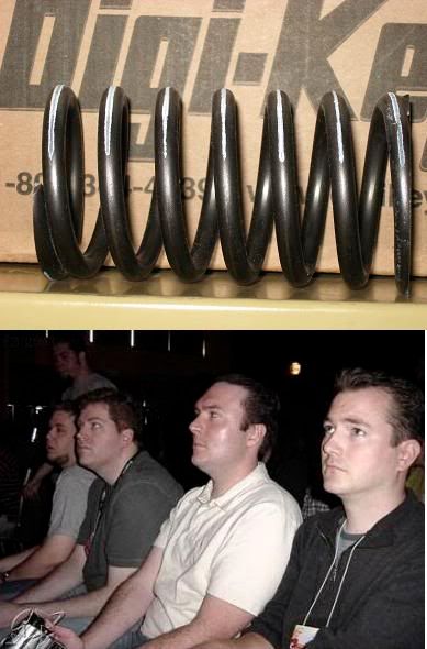
OK, first you need to get yourself a LVT, and whatever hardware you want to use to mount it to your shock. I got the LVT off ebay for $20.
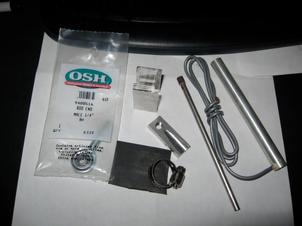
Here it is mounted. The LVT I got only had 3.4" of stroke, yet my suspension has about 5". Well, if I mount half of the LVT to the middle of the spring, that will reduce the leverage by about half. I used a mini rod end to give the upper joint some rotational freedom (since the spring bends a bit upon compression) and I also mounted the lower joint with some rubber in it to give it slight bending freedom, in case the alignment isn't perfect.
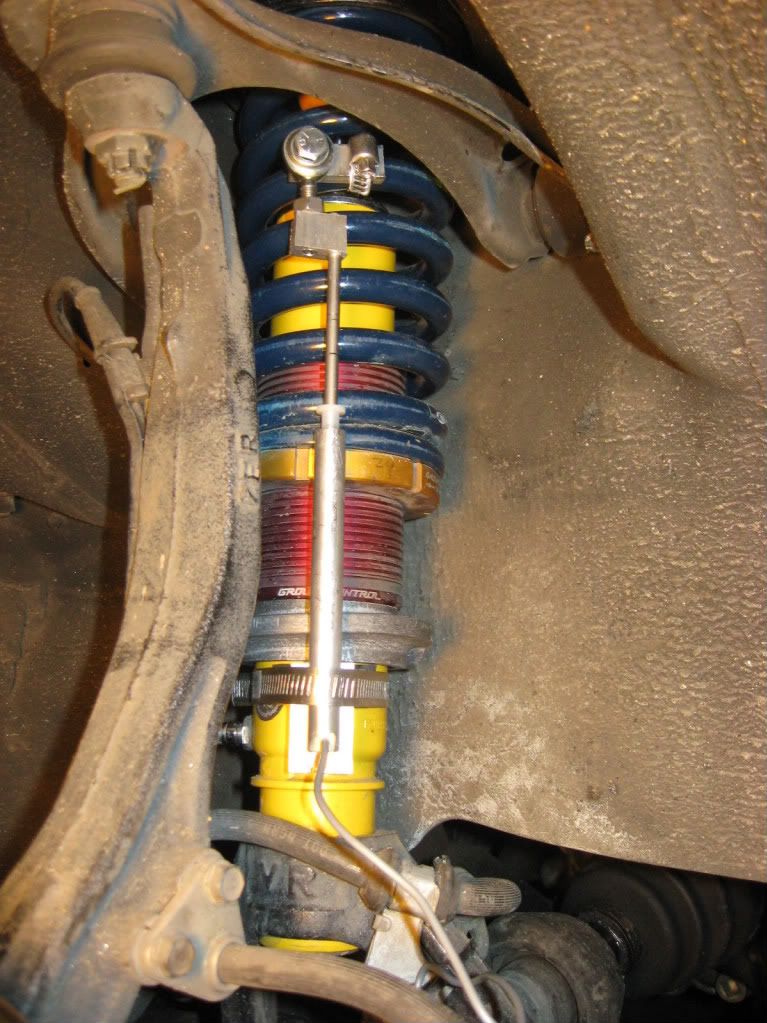
Major disclaimer: This setup doesn't actually measure shock velocity. There's an extra upper spring bushing (which is mostly compressed anyway and doesn't deflect much) and also the shock top hat bushings, which deflect maybe 1/8" or so? I know I can cut down on this if I get stiffer top hat bushings, but I didn't feel like it.
Go route the wire into the cabin somehow. I used the hole in the firewall next to the battery, although that shares a cable with my relocated battery. (Yeah, I know, if I somehow had more horsepower or ran wider front tires, I wouldn't need to redistribute weight...ok being facetious again). This turned out to be kind of sub-optimal since I have engine rpm pickup on my signal now. Gotta do something about it...
Here's my girlfriend sitting in the passenger seat helping with the data acquisition. Labview + NI USB-6008. Oh hey, it's the same one that helped with the shock dyno. Yay for versatility.
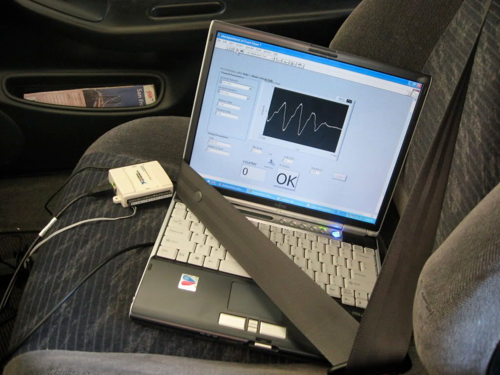
You need to be able to play Matlab, or some other kind of data analysis program. Or you could spend hundreds on proprietary software, and have others do it for you. Pansy.
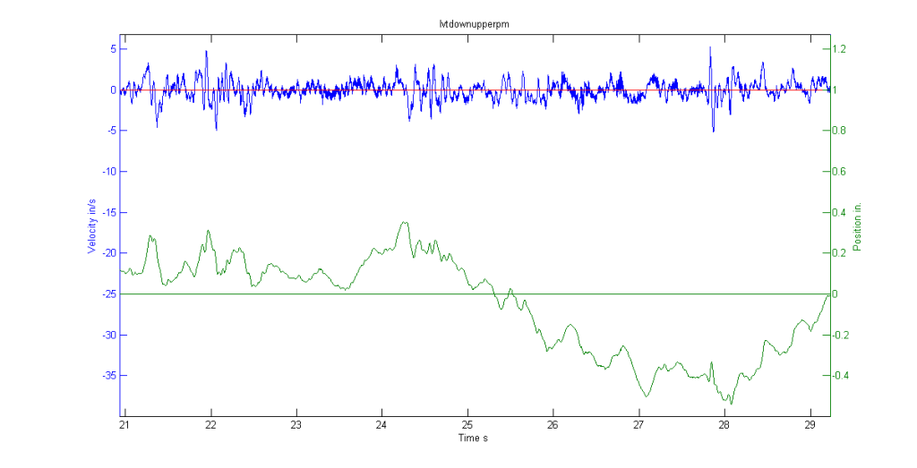
Here's a velocity + integrated position plot for me driving a section of road up in the hills. The first segment is paved but windy, and the second is a bit lumpier.
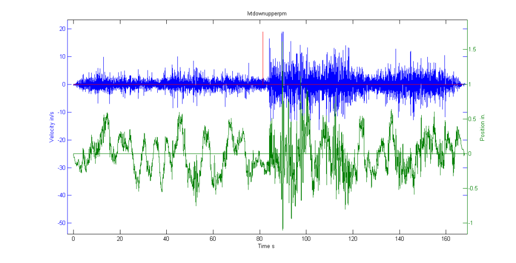
You can see in the position plot how I sway the car back and forth over several seconds.
Next is a more zoomed in view. I acquired the data at 500 Hz.
There's a few characteristic frequencies that shows up better in a FFT.
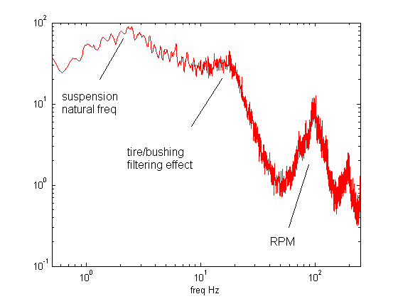
These frequencies make sense, right?
The thing that's pretty annoying is this extra resonance lump near 15 Hz, which I think is some kind of tire-lca-lca bushing mode, i.e. unspring weight. I don't think it has anything to do with my mounting mechanism. If anybody has any more comments about this, especially how to get rid of it in my measurements, I'm all ears.
Next up is me hitting a big, smooth dip in the road going about 30+ mph. That got the velocities up to about 20 ips and deflected the shock about 2". I still had about 0.5" travel left before hitting the bump stop, I think. But why didn't my shocks bottom out on these Bilsteins, when they would easily bottom out on the Konis? Life is full of mysteries, I guess. (Being facetious again)
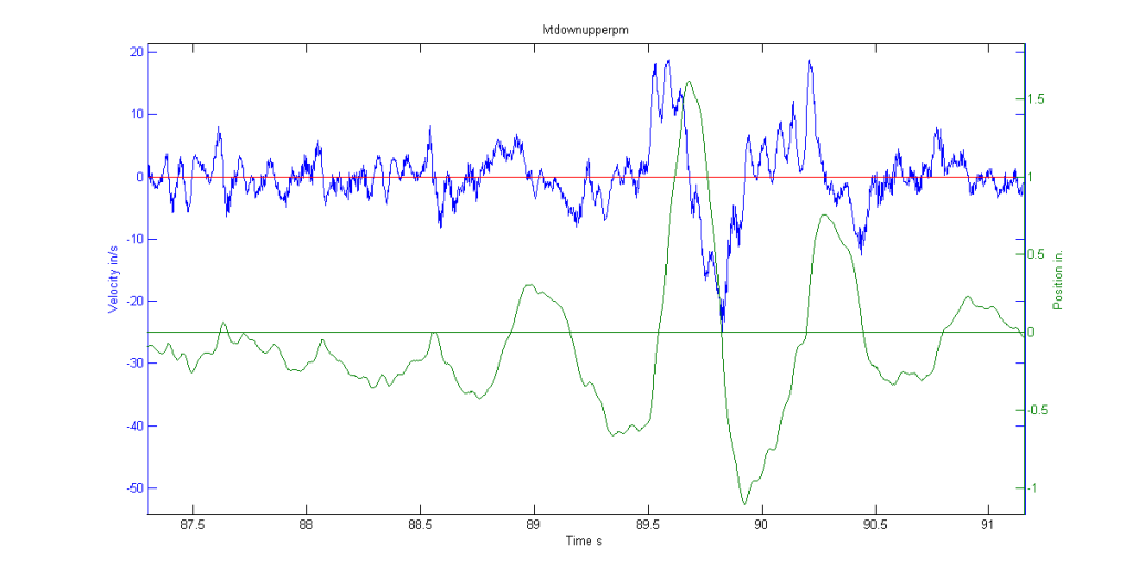
One of the things that bothered me was the really high shock velocities I was measuring. I guess the shock is experiencing slightly less movement than measured due to the deflection of the bushings. But in this case, "integrals don't lie", as I sometimes say, and the shock probably did more 2" over the course of a quarter second or so.
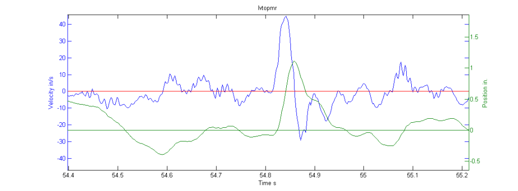
Next up is me hitting a sharper edge bump, where I measured 40 ips. I don't know if this number is "real" or not. Do you think a wheel could deflect about 1.5" in 1/20th of a second? That would at least give 20 ips (if you consider motion ratio). Even then, it wasn't that horrible of a bump or anything.
Finally, here is a token histogram for show.
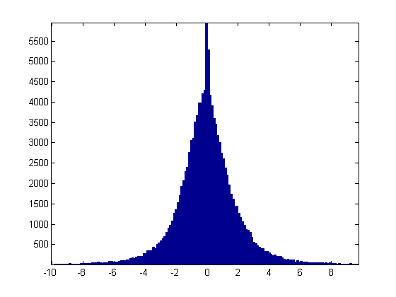
You can be like Dennis Grant or that Claude Rouelle (sp?) guy and try to say something about your damping from the shape of the histogram. I think the histogram is supposed to be used under all out racing conditions, where you are constantly shifting the car around. In my case, I'm kind of using it to measure bump absorption. The histogram is pretty symmetrical, so either I got the damping set exactly right, or it's just the nature of bumps that gives this kind of a distribution anyway. I also think that 15 Hz mode is polluting the data.
It's been raining here, and my tires are dangerously low on grip, so there won't be any aggressive swerving tests any time soon.
Anybody have any advice to get a more meaningful interpretation of the data?
Less cost
No moving parts to wear out (sorta)
Better quality data (since you don't have to differentiate an already noisy position signal but can go straight to velocity)
Etc
I initially had a rotational potentiometer system, but that was just too crappy.
OK, first you need to get yourself a LVT, and whatever hardware you want to use to mount it to your shock. I got the LVT off ebay for $20.
Here it is mounted. The LVT I got only had 3.4" of stroke, yet my suspension has about 5". Well, if I mount half of the LVT to the middle of the spring, that will reduce the leverage by about half. I used a mini rod end to give the upper joint some rotational freedom (since the spring bends a bit upon compression) and I also mounted the lower joint with some rubber in it to give it slight bending freedom, in case the alignment isn't perfect.
Major disclaimer: This setup doesn't actually measure shock velocity. There's an extra upper spring bushing (which is mostly compressed anyway and doesn't deflect much) and also the shock top hat bushings, which deflect maybe 1/8" or so? I know I can cut down on this if I get stiffer top hat bushings, but I didn't feel like it.
Go route the wire into the cabin somehow. I used the hole in the firewall next to the battery, although that shares a cable with my relocated battery. (Yeah, I know, if I somehow had more horsepower or ran wider front tires, I wouldn't need to redistribute weight...ok being facetious again). This turned out to be kind of sub-optimal since I have engine rpm pickup on my signal now. Gotta do something about it...
Here's my girlfriend sitting in the passenger seat helping with the data acquisition. Labview + NI USB-6008. Oh hey, it's the same one that helped with the shock dyno. Yay for versatility.
You need to be able to play Matlab, or some other kind of data analysis program. Or you could spend hundreds on proprietary software, and have others do it for you. Pansy.
Here's a velocity + integrated position plot for me driving a section of road up in the hills. The first segment is paved but windy, and the second is a bit lumpier.
You can see in the position plot how I sway the car back and forth over several seconds.
Next is a more zoomed in view. I acquired the data at 500 Hz.
There's a few characteristic frequencies that shows up better in a FFT.
These frequencies make sense, right?
The thing that's pretty annoying is this extra resonance lump near 15 Hz, which I think is some kind of tire-lca-lca bushing mode, i.e. unspring weight. I don't think it has anything to do with my mounting mechanism. If anybody has any more comments about this, especially how to get rid of it in my measurements, I'm all ears.
Next up is me hitting a big, smooth dip in the road going about 30+ mph. That got the velocities up to about 20 ips and deflected the shock about 2". I still had about 0.5" travel left before hitting the bump stop, I think. But why didn't my shocks bottom out on these Bilsteins, when they would easily bottom out on the Konis? Life is full of mysteries, I guess. (Being facetious again)
One of the things that bothered me was the really high shock velocities I was measuring. I guess the shock is experiencing slightly less movement than measured due to the deflection of the bushings. But in this case, "integrals don't lie", as I sometimes say, and the shock probably did more 2" over the course of a quarter second or so.
Next up is me hitting a sharper edge bump, where I measured 40 ips. I don't know if this number is "real" or not. Do you think a wheel could deflect about 1.5" in 1/20th of a second? That would at least give 20 ips (if you consider motion ratio). Even then, it wasn't that horrible of a bump or anything.
Finally, here is a token histogram for show.
You can be like Dennis Grant or that Claude Rouelle (sp?) guy and try to say something about your damping from the shape of the histogram. I think the histogram is supposed to be used under all out racing conditions, where you are constantly shifting the car around. In my case, I'm kind of using it to measure bump absorption. The histogram is pretty symmetrical, so either I got the damping set exactly right, or it's just the nature of bumps that gives this kind of a distribution anyway. I also think that 15 Hz mode is polluting the data.
It's been raining here, and my tires are dangerously low on grip, so there won't be any aggressive swerving tests any time soon.
Anybody have any advice to get a more meaningful interpretation of the data?
Last edited by beanbag; 12-16-2008 at 04:36 AM.
 12-16-2008, 04:59 PM
#2
Honda-Tech Member
ive been meaning to do something exactly like this for a while. picked up a cheap LVDT off ebay, lab tested it and thats about it... lol.
interesting solution to limiting stroke. but what happens when the spring shifts?
i dunno about the spikes of displacement, have you tried bench testing it? put a physical stop and tap it with a hammer to get sudden jolt. see if it measures a displacement greater than possible.
your thoughts on using a stock TPS sensor as a 5V rotary transducer? i thought of rigging that up to brake pedals, suspension arms, steering wheel.
12-16-2008, 05:42 PM
#3
Honda-Tech Member
Thread Starter
There is a little bit of flex in the mounting mechanism, so if the spring shifts a bit, it shouldn't be a problem. Else you could also use a rod end on the LVT mount to give it more bending freedom.
That's a good idea for testing it. I'll try it on my other LVT.
I would use a conductive plastic potentionmeter instead of a TPS, just coz it's smaller and cheaper to get.
Brake pedal I would rather have load cell pressure transducer.
Suspension arms - I tired that with pots, and it didn't work very well because the motion is too small and the flex from bushings and other stuff is large.
Steering wheel - I dunno, you'd probably have to get a multi turn pot or pot that doesn't have a rotation stop.
12-16-2008, 06:34 PM
#4
Honda-Tech Member
TPS with the right pulley and dynamics i would imagine would overcome all that you mentioned i would think.
to me, TPS are pretty cheap from the junkyard. lol. i would imagine reliable. just not sure on the resolution.
to me, TPS are pretty cheap from the junkyard. lol. i would imagine reliable. just not sure on the resolution.
12-17-2008, 11:12 PM
#5
Honda-Tech Member
There is a little bit of flex in the mounting mechanism, so if the spring shifts a bit, it shouldn't be a problem. Else you could also use a rod end on the LVT mount to give it more bending freedom.
That's a good idea for testing it. I'll try it on my other LVT.
I would use a conductive plastic potentionmeter instead of a TPS, just coz it's smaller and cheaper to get.
Brake pedal I would rather have load cell pressure transducer.
Suspension arms - I tired that with pots, and it didn't work very well because the motion is too small and the flex from bushings and other stuff is large.
Steering wheel - I dunno, you'd probably have to get a multi turn pot or pot that doesn't have a rotation stop.
That's a good idea for testing it. I'll try it on my other LVT.
I would use a conductive plastic potentionmeter instead of a TPS, just coz it's smaller and cheaper to get.
Brake pedal I would rather have load cell pressure transducer.
Suspension arms - I tired that with pots, and it didn't work very well because the motion is too small and the flex from bushings and other stuff is large.
Steering wheel - I dunno, you'd probably have to get a multi turn pot or pot that doesn't have a rotation stop.
In other words, the mounting position on the coil will always move at the Vcoil = Vshaft*(Li/L), where Vshaft is shaft velocity, Li is instantaneous distance from bottom of coil to LVT mount on coil, and L is the instantaneous compressed length of spring. Since you want Vshaft, then you can compute it from this formula.
Of course, a coil spring is really a torsional spring in disguise. This means that the spring wire will rotate through some angle theta (twist about the center of the spring wire) based on the amount of total vertical spring deflection. This angle theta is a bit more difficult to calculate since its true value will depend on the end boundary conditions - i.e. both ends of the spring are close to having a fixed angle boundary condition - thus, the spring wire is fixed from rotation at the ends thanks to the grounded flat ends. By assuming no coil rotation, there will be some error in your calculations, but this is nevertheless an interesting thread and solution. This also is nice ad hoc problem that can show limitations to solving certain problems, whereas another solution can be shown to eliminate or at least mitigate the errors such as by using a full length sensor and eliminating the wire rotation error.
Last edited by Johnny Mac; 12-17-2008 at 11:37 PM.
12-18-2008, 01:18 AM
#6
Honda-Tech Member
Thread Starter
Hello JM,
Thanks for commenting on this. You may have missed the part where I mention that I purposely mount the upper end of the LVT at the approximate halfway point of the spring because I don't have enough travel on the LVT. I got it for cheap off ebay, so I didn't really have a choice. Ideally, I'd have something like a 5-6" lvt, and then I would make the upper mounting point the top hat.
The next issue you bring up is kind of interesting to think about. But I don't think it is a problem at all. Here's why:
First of all, if you look at the scrape marks on the spring (from my outer dust cover, not shown in this pic), you can see that they form a narrow line around the outer edge of the spring, which means that if the spring wire is twisting at all, it's not doing it by much.
But on a more fundamental level, I don't think the spring wire is twisting at all (I mean, yes it twists like a torsional spring, but not in the way you are worrying about). For example, if you consider the middle coil, it can't have any twist because that would break symmetry. (The exact type of symmetry I don't know the term for). But the longer answer is that there's no reason for the outer edge of the middle coil to twist either upwards or downwards. That's because I can take the spring and flip it upside down, and it would be the exact same spring, so the twist must be exactly the same. The only kind of twist that survives this operation is no twist at all.
One can use this same kind of argument and say, ok the middle of the spring has no twist, how about the 1/4 way point? The same reasoning applies, so the 1/4 way point has no twist either, and therefore there is no twist along the entire length of the spring. That might be very slightly wrong because of the slightly different boundary conditions, but still to first order...
Any even if there were a slight twist, it doesn't matter because it would probably be linear or at least monotonic, so would only give a small error in my LVT sensitivity.
I also re-routed the wire, but found out that the RPM signal is still there. It turns out that it comes from the engine actually slightly shaking the car. That's how sensitive this sensor is.
The bigger problem is still that 15 Hz mode, which I don't know what to do with.
Last edited by beanbag; 12-18-2008 at 01:29 AM.
12-18-2008, 04:19 AM
#7
Honda-Tech Member
Hello JM,
First of all, if you look at the scrape marks on the spring (from my outer dust cover, not shown in this pic), you can see that they form a narrow line around the outer edge of the spring, which means that if the spring wire is twisting at all, it's not doing it by much.
But on a more fundamental level, I don't think the spring wire is twisting at all (I mean, yes it twists like a torsional spring, but not in the way you are worrying about). For example, if you consider the middle coil, it can't have any twist because that would break symmetry. (The exact type of symmetry I don't know the term for). But the longer answer is that there's no reason for the outer edge of the middle coil to twist either upwards or downwards. That's because I can take the spring and flip it upside down, and it would be the exact same spring, so the twist must be exactly the same. The only kind of twist that survives this operation is no twist at all.
One can use this same kind of argument and say, ok the middle of the spring has no twist, how about the 1/4 way point? The same reasoning applies, so the 1/4 way point has no twist either, and therefore there is no twist along the entire length of the spring. That might be very slightly wrong because of the slightly different boundary conditions, but still to first order...
Any even if there were a slight twist, it doesn't matter because it would probably be linear or at least monotonic, so would only give a small error in my LVT sensitivity.
I also re-routed the wire, but found out that the RPM signal is still there. It turns out that it comes from the engine actually slightly shaking the car. That's how sensitive this sensor is.
K = d^4*G/(8*N*D^3)
where:
k = spring rate (lb/in)
d = spring wire diameter (inch)
D = Effective Coil Diameter (inch)
N = Active Coils (unitless)
G = Shear modulus (lb/in*in)
I then found an Eibach ERS 700.250.500 and proceeded to measure it and the following is the findings:
d = .465 in
D = 3.035 in
N = 4.75
G = 11.5 Msi (million psi)
From these numbers and placing them in the equation, I get:
Spring rate K = 506 lbs/in so it is very close to the K = 500 lb/in rating.
Then, I came up with equation for total twist angle:
Theta = 16*F*N*D^2/(G*d^4)
Where F is force at spring ends
So, lets assume you compress the spring 1 inch, thus imparting a 500 lb load into it and solving the equation above and converting to degrees, you get:
Theta = 37.3 degrees, which by my boundary conditions, this would yield a 18.7 degree rotation (clockwise) on top and a negative 18.7 degree rotation on the bottom (counterclockwise). Also, you would get a zero degrees on rotation in the center of the spring.
So, by placing your sensor end at the center of the spring, you get no rotation and you will get a true reading of 1/2 of the shaft velocity there. However, anywhere elso and you will get a linear error that can be quite high.
And yes, the rotation of the spring about its helical path centerline is precisely as I mentioned in my previous post. If there wasn't this angle of deflection, than the torsional model wouldn't work - but we know it does and it makes sense from a free body perspective (i.e. the sum of forces, moments, and torques must be zero for a non accelerating object). In addition, the potential energy in the spring must equal the strain energy within the spring itself.
Trending Topics
12-18-2008, 11:07 AM
#8
Honda-Tech Member
Thread Starter
Hello again,
You need to take into account the geometry of a helical coil and what happens when you compress it. Yes, there is torsional twist within every given segment of wire, but in the reference frame of an observer looking at the side of the spring, this twist goes into changing the angle of the coils, but the outermost edge of each individual coil does not twist inwards.
There's also the additional complexity of bending moments for the coils, but I won't go into that.
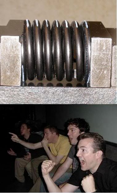
Consider the case of a tender or helper spring that has flat cross section coils. Note how those coils stay nice and flat (relative to the ground end of the spring) upon compression.
I'm pretty sure that if you took a coil spring, and drew a line along the outermost edge of the coils, and then compressed this spring, the line you drew would still be at the outermost edge, i.e. no twist relative to the viewer. Even though the spring wire is twisting about a line/helical curve that runs thru its center. It all depends on how you parameterize this twist.
Going by your example, where you figure that if you took a 7" spring and compressed it 1", that there would be 19 deg rotation at the ends, then how about I take a 250 lbs 14" spring and compress it 5"? That would give 5x the twist according to you, which means that at some point, a coil is twisted 95 degrees relative to the viewer? I don't think so.
You need to take into account the geometry of a helical coil and what happens when you compress it. Yes, there is torsional twist within every given segment of wire, but in the reference frame of an observer looking at the side of the spring, this twist goes into changing the angle of the coils, but the outermost edge of each individual coil does not twist inwards.
There's also the additional complexity of bending moments for the coils, but I won't go into that.
Consider the case of a tender or helper spring that has flat cross section coils. Note how those coils stay nice and flat (relative to the ground end of the spring) upon compression.
I'm pretty sure that if you took a coil spring, and drew a line along the outermost edge of the coils, and then compressed this spring, the line you drew would still be at the outermost edge, i.e. no twist relative to the viewer. Even though the spring wire is twisting about a line/helical curve that runs thru its center. It all depends on how you parameterize this twist.
Going by your example, where you figure that if you took a 7" spring and compressed it 1", that there would be 19 deg rotation at the ends, then how about I take a 250 lbs 14" spring and compress it 5"? That would give 5x the twist according to you, which means that at some point, a coil is twisted 95 degrees relative to the viewer? I don't think so.
12-18-2008, 11:36 AM
#9
Honda-Tech Member
Join Date: Jun 2000
Location: Concord, CA, USA
Posts: 2,748
Likes: 0
Received 0 Likes
on
0 Posts
We did one on the civic a few years ago. I can't take full credit, as the idea came from Tommy Lo.
We compared it with the expensive Penny Giles sensor and it was dead on. We used it for a full year to collect data with great reliability.


We compared it with the expensive Penny Giles sensor and it was dead on. We used it for a full year to collect data with great reliability.
12-18-2008, 11:47 AM
#10
Honda-Tech Member
Thread Starter
That post helped inspire me to rig up a potentiometer based system also, but I deemed it a failure because I considered the pot to be too noisy, and also there were backlash problems that gave all bumps a funny profile.
12-18-2008, 07:47 PM
#12
Honda-Tech Member
Thread Starter
I suppose I could, although that would make it a wheel velocity sensor. It would be two more bushings away from measuring the shock velocity, though. I guess it depends on what you want to accomplish.
12-18-2008, 09:50 PM
#13
Honda-Tech Member
Hello again,
You need to take into account the geometry of a helical coil and what happens when you compress it. Yes, there is torsional twist within every given segment of wire, but in the reference frame of an observer looking at the side of the spring, this twist goes into changing the angle of the coils, but the outermost edge of each individual coil does not twist inwards.
There's also the additional complexity of bending moments for the coils, but I won't go into that.
Consider the case of a tender or helper spring that has flat cross section coils. Note how those coils stay nice and flat (relative to the ground end of the spring) upon compression.
I'm pretty sure that if you took a coil spring, and drew a line along the outermost edge of the coils, and then compressed this spring, the line you drew would still be at the outermost edge, i.e. no twist relative to the viewer. Even though the spring wire is twisting about a line/helical curve that runs thru its center. It all depends on how you parameterize this twist.
Going by your example, where you figure that if you took a 7" spring and compressed it 1", that there would be 19 deg rotation at the ends, then how about I take a 250 lbs 14" spring and compress it 5"? That would give 5x the twist according to you, which means that at some point, a coil is twisted 95 degrees relative to the viewer? I don't think so.
But I'm sure you will have a "thought" answer to whatever ails us in the motorsports arena and that will suffice for you. However, some of us do things entirely differently and thats fine as well.
12-19-2008, 12:22 AM
#14
Honda-Tech Member
 12-19-2008, 07:40 PM
#17
Honda-Tech Member
Thread Starter
I'm pretty sure that if you took a coil spring, and drew a line along the outermost edge of the coils, and then compressed this spring, the line you drew would still be at the outermost edge, i.e. no twist relative to the viewer. Even though the spring wire is twisting about a line/helical curve that runs thru its center. It all depends on how you parameterize this twist.
Yes, true the coil curvature and helix angle do factor in the twist equation in the laboratory frame of reference, but to say there is no twist for a given spring rate and geometry would be to suggest that all geometric factors as well as the loading factors cancel each other out would not be correct.
 12-21-2008, 02:46 AM
#19
Honda-Tech Member
Thread Starter
By integrating the velocity to find position, I figured out that the sensitivity was 10% down from what the spec sheet said.
At some very high velocity spikes, the signal was exceeding the input range of the DAQ, which explained why sometimes the final integral wouldn't work out.
It's also possible that even though I use a sampling speed of 0.5-1 kHz, maybe I am missing some spikes. The solution to this would be to put a low pass filter at the input, with a roll-off freq somewhere near the sampling freq.
12-21-2008, 04:41 AM
#20
Honda-Tech Member
Thread Starter
OK, getting back on topic, I did some more driving around today when the roads were dry. Here's a plot of me doing some swerves, where by "swerve", I mean making quick tugs on the steering wheel.
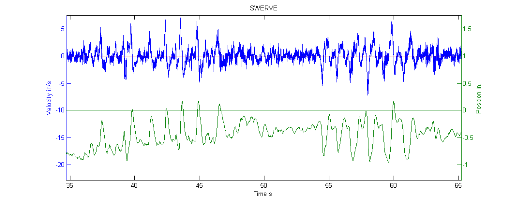
You can see that the peak shock velocities were up to about 5 ips, although I suspect that in autocross slaloms, where you turn the wheel quickly but more smoothly, you might hit around the expected 2-3 ips.
OK, my question is this: How should I go around interpreting this data to help me set my shock valving? I've read that you set the knee point to control chassis roll and other "self generated" movements. So right now, I have my shocks valved about 70% critical at low speed and then digress over at about 2.2 ips or so. The shock does feel a bit underdamped, but I expected that to a certain extent because it IS underdamped, but I guess what I mean is that it is even more underdamped than optimal.
If you look at some of the other velocity plots I made, you can see that there does seem to be a lot of 2Hz bobbing. I mean, the compression damping is obviously underdamped, but also, a lot of this bobbing (due to hitting dips and etc) happens at 3 ips or above, where the digression causes the shock to be even more underdamped.
Earlier, I had the knee set a little higher, and also had more high speed damping, but I suspected that it was causing the wheel to lose traction over rapid bumps.
Anyway, I was wondering if I should increase the slope of the low speed damping, or move the knee point up, or increase the slope of the high speed damping or ...?
Last edited by beanbag; 12-21-2008 at 04:47 AM.
12-21-2008, 05:10 PM
#21
Honda-Tech Member
Join Date: Jun 2002
Location: MA
Posts: 3,569
Likes: 0
Received 0 Likes
on
0 Posts
Can't say. I call Koni and say something like "My car feels underdamped and sluggish in slaloms" or "I keep increasing X and the car gets better, but now I can't increase X anymore because I'm at the limit of the range". Koni then does some work to my shocks, sends them back to me, and I resume testing. For the cost of having my shocks rebuilt I have a shock engineer instead of having to learn how to be that as well as the chassis engineer, mechanic, chief of marketing, and driver. I think I'm getting an excellent deal.
12-21-2008, 06:44 PM
#23
Honda-Tech Member
Join Date: Jun 2002
Location: MA
Posts: 3,569
Likes: 0
Received 0 Likes
on
0 Posts
Yep. Hell, half the time I'm standing there BS'ing with the guy doing the work and watch him dyno my shocks. (you see, Koni shows up at the Solo Nats and will service your shocks for the cost of parts even) The rest of the time, I've got the cell number of Lee Grimes and know I can call him if I'm stuck (and have). Not like I wouldn't be able to tell if they didn't do what I had asked anyhow, especially if I could tell that I needed something changed on the shocks in the first place.
12-22-2008, 09:28 AM
#24
Honda-Tech Member
Join Date: Jan 2003
Location: Charlotte, NC
Posts: 3,788
Likes: 0
Received 0 Likes
on
0 Posts
12-22-2008, 12:57 PM
#25
Honda-Tech Member
Join Date: May 2002
Location: cali
Posts: 13,483
Likes: 0
Received 0 Likes
on
0 Posts
Is this mental masturbation?
Or is it a way for you to make your self feel really smart?