
JZ CLK.
 11-15-2013, 03:47 PM
#1
Honda-Tech Member
Thread Starter

Join Date: Sep 2001
Location: central, nj, usa
Posts: 2,496
Likes: 0
Received 0 Likes
on
0 Posts
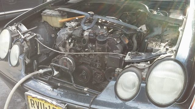
TL;DR: Putting a 2JZ into a 2000 CLK.
$900
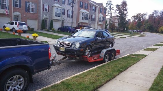
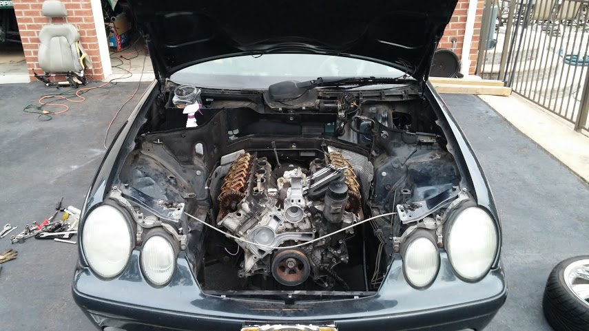
I got her home. First thing I did was try to see if the engine was actually dead.
It was.
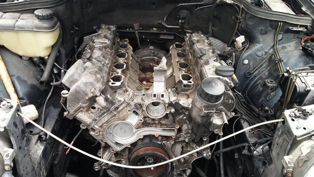
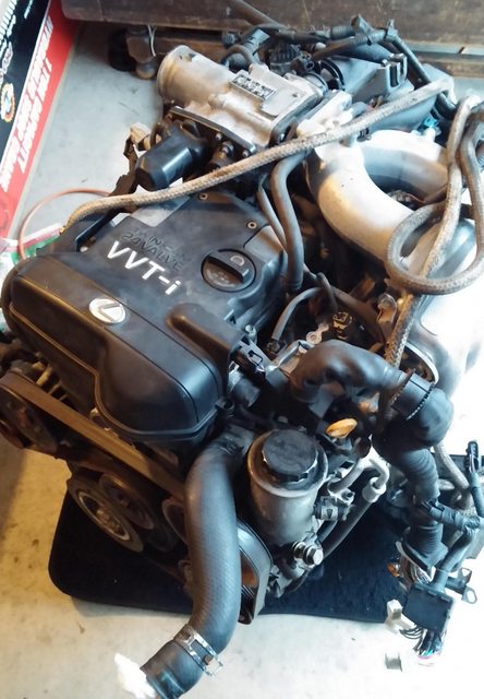
The engine is COVERED in sludge. Seriously, it's over an inch thick in some places.
I guess the PO wasn't big on maintenance.
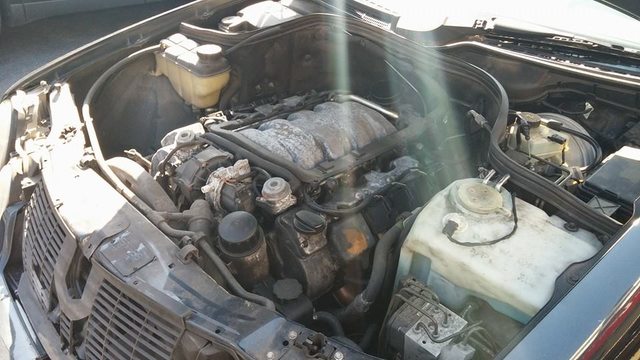
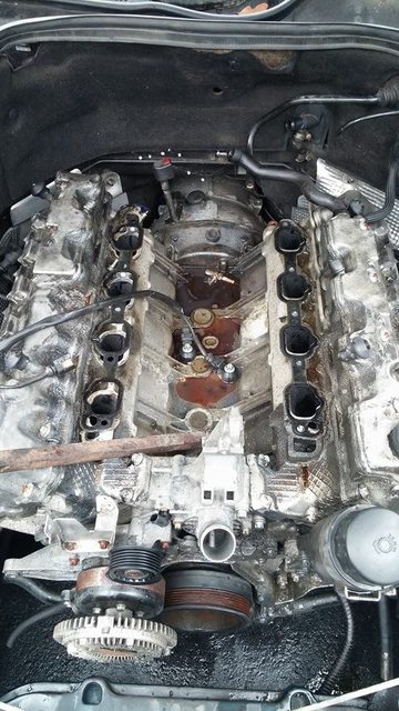
intake off. yes, thats an old spark plug in the valley.
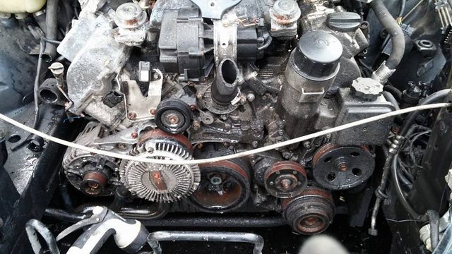
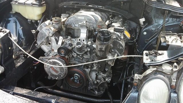
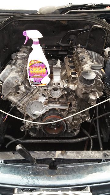
water pump/pulleys off.
size comparison.
growing pile of garbage:
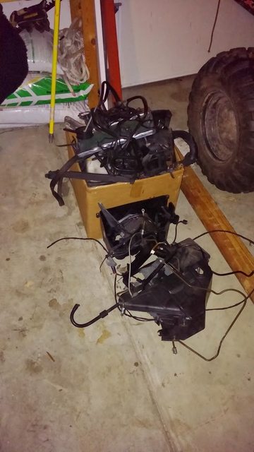
abs brick/computer/paperweight removed:
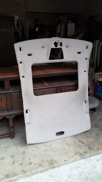
started pulling apart the interior.
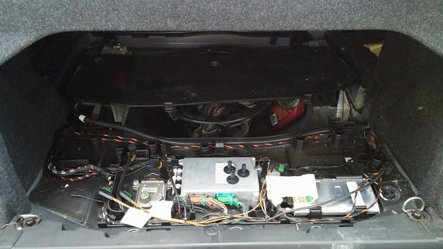
more computers:
just to give you an idea what i'm currently dealing with,
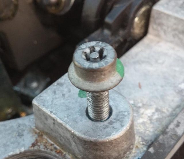
fffffffuuuuuuuuuuuuu tamper proof bolts.
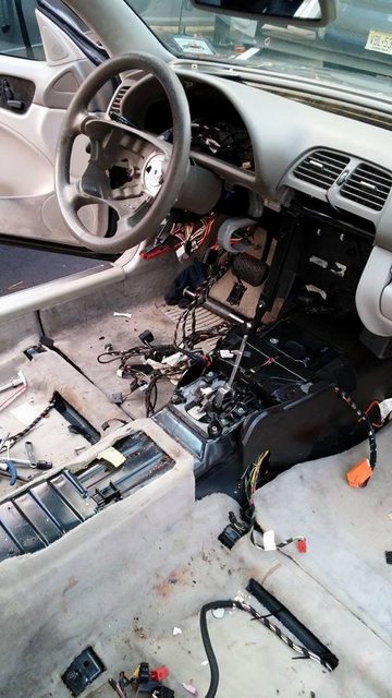
random 1/2 dash out pic.
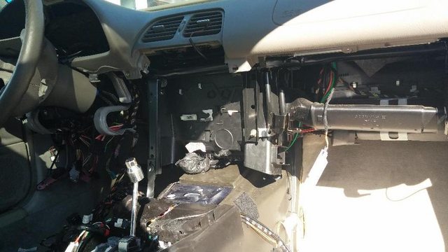
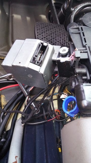
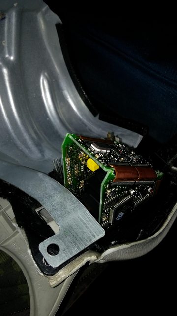
Here's the steering wheel lock. Needed to move the car, it was locked.
I beat the **** out of it with a hammer, it opened. Found a mess of electronics inside.
Couldn't bother to figure it out, sawzalled it off. Problem solved.
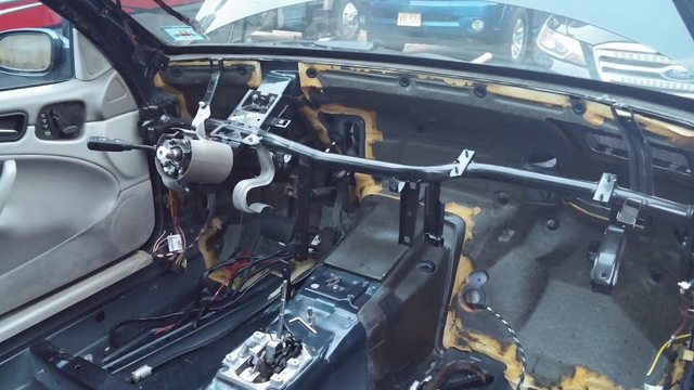
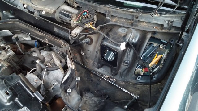
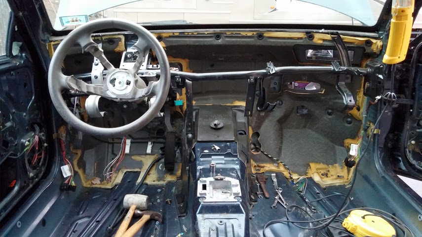
Here's the dashboard out:
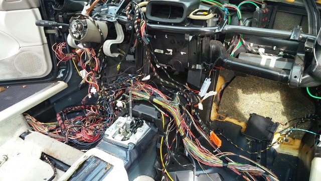
some wires out.
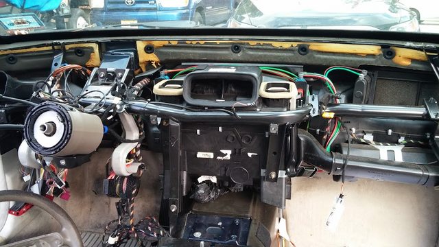
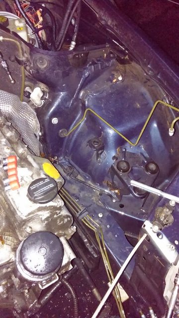
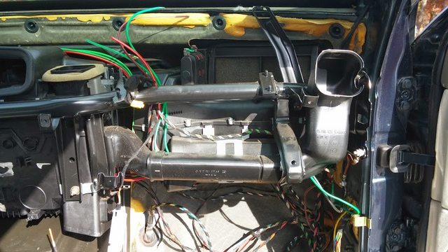
you can see the vacuum lines that control the entire heating/ac system here:
it's a complete disaster trying to figure it out. there are vacuum lines for heater and door locks, coaxial for something else, and fiber optic for another thing. glad it's all out.
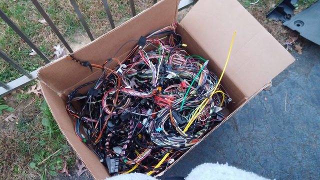
some of the wiring from the body:
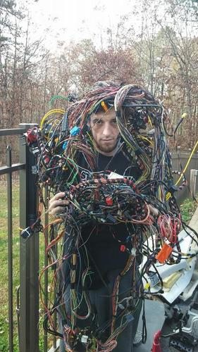
edit; and why the hell not:
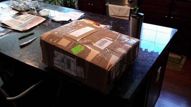
Overnight parts from Japa.... Germany!
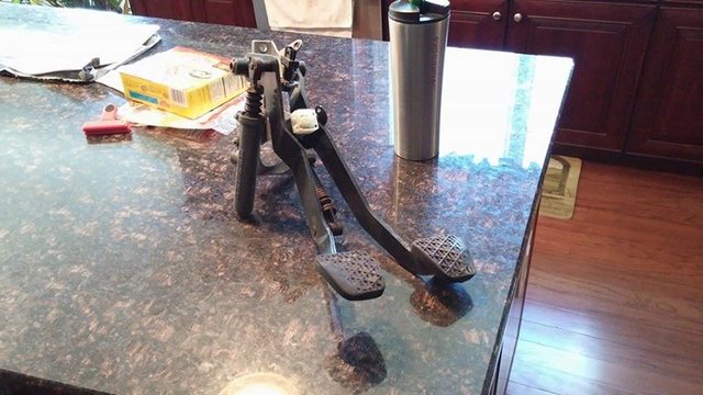
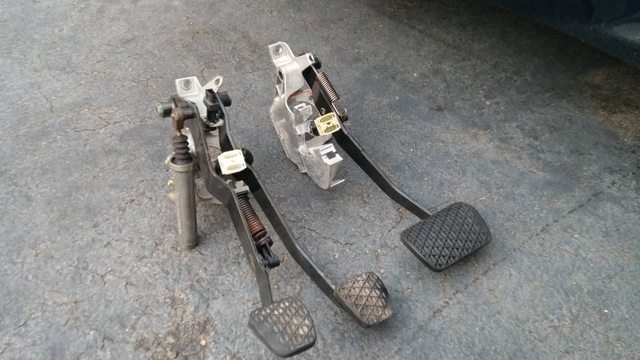
pedal assemblies side by side. say hello and goodbye.
nice to have an oem-drop in option.
booster came out as well, looks as if it's standard mounting size/holes.
i was considering this: http://www.chasebays.com/product/uni...ter-eliminator
but i'm a bit weary with the curb weight of the vehicle, and i don't know the pedal ratio.
the merc one has like 6 sensors going into it, one of which i destroyed... not worth the hassle of reusing.
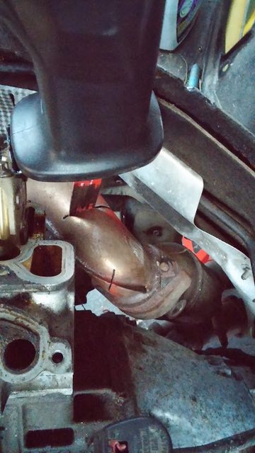
So... started removing things from the underbody.
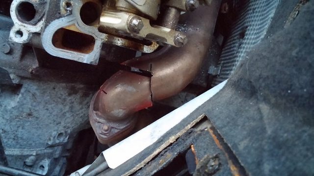
The exhaust is rusted to all hell. I got the catback off, the midpipes are stuck.
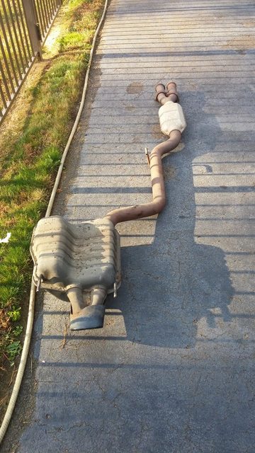
The bolts are rusted and they're impossible to reach anyway. The cat's bulge right after the bolts, meaning you can't use a socket. :banghead:
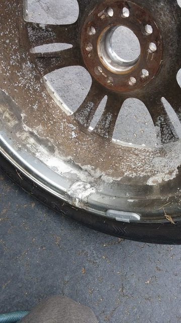
I pulled the front wheel off that wouldn't hold air while I was working.
Look at this gem: WHAT THE ****?
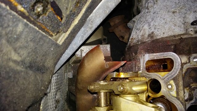
i couldn't let the midpipe defeat me that easily.
ran to home depot, got the right sawzall blade.

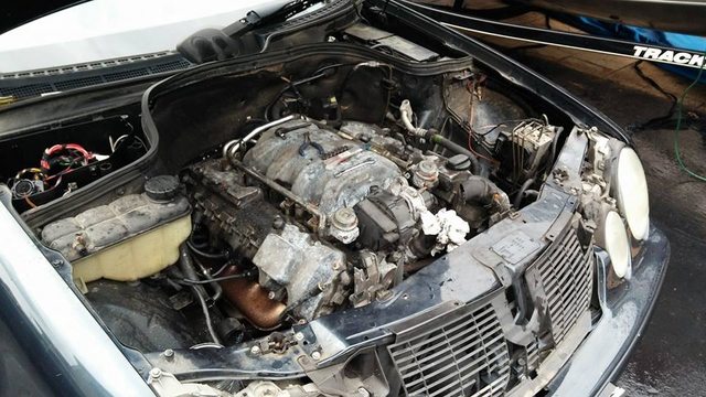
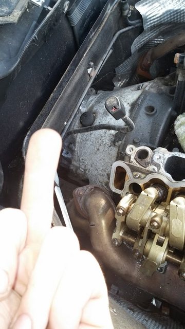
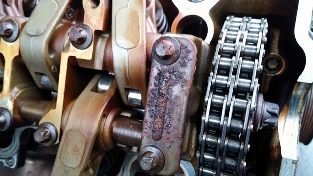
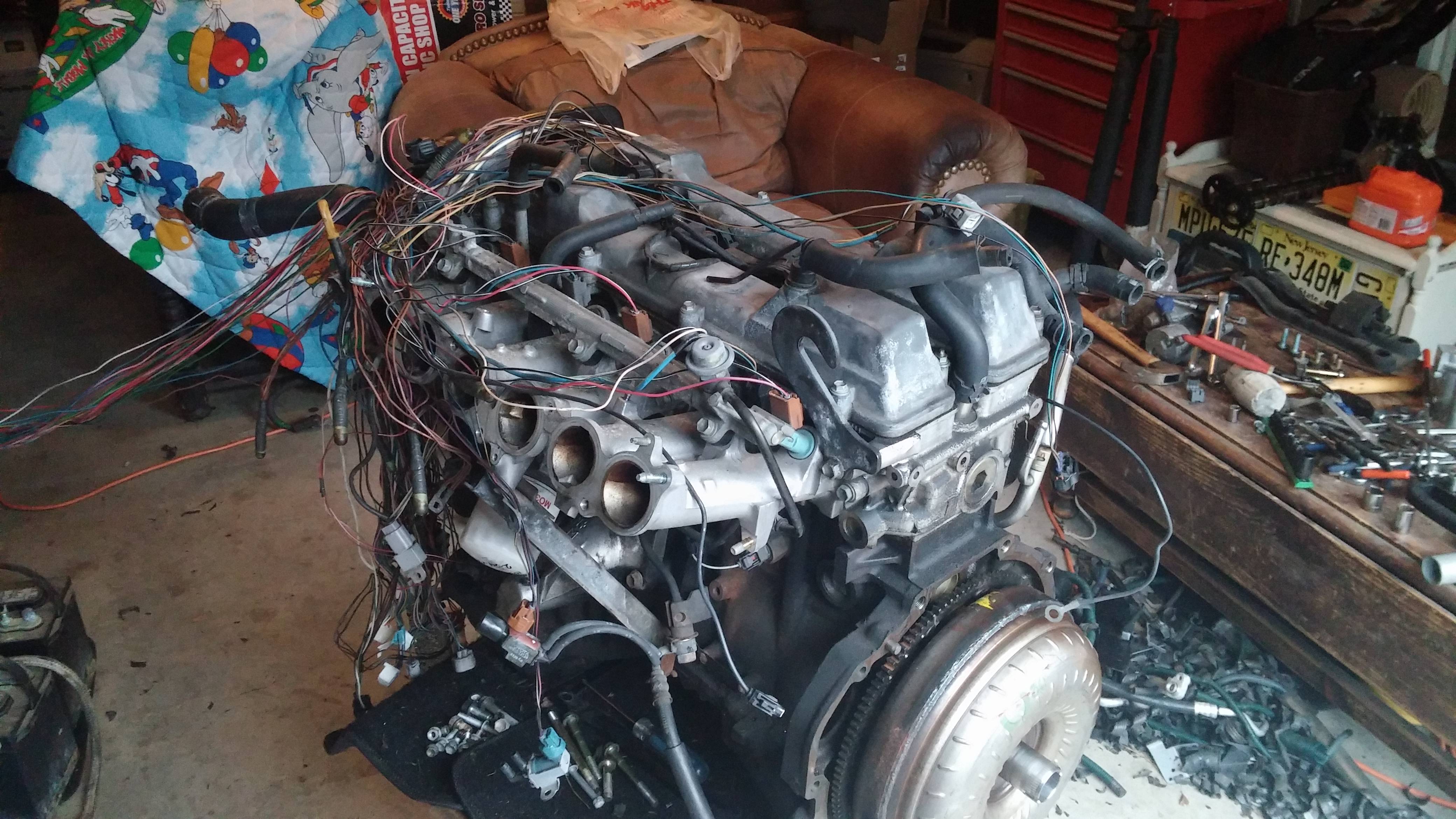
under the valve cover:
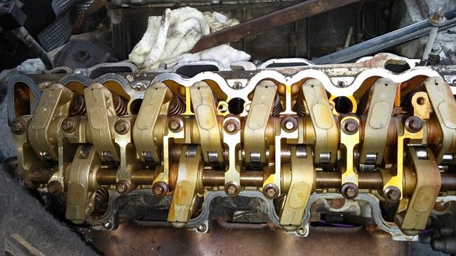
this is nice:
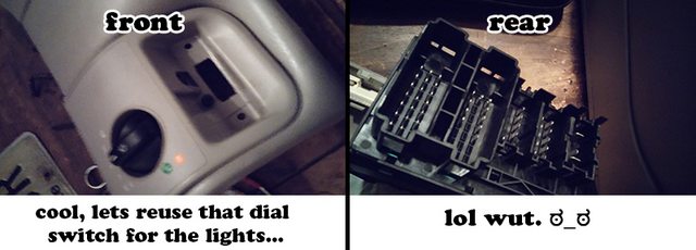
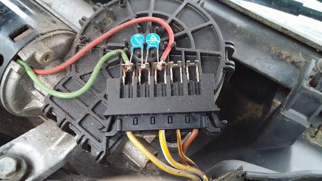
one more pic of the still-current-mystery-at-hand. (how to wire this)
aaaaaaand finally- here's where i am at overall:
$900
I got her home. First thing I did was try to see if the engine was actually dead.
It was.
The engine is COVERED in sludge. Seriously, it's over an inch thick in some places.
I guess the PO wasn't big on maintenance.
intake off. yes, thats an old spark plug in the valley.
water pump/pulleys off.
size comparison.
growing pile of garbage:
abs brick/computer/paperweight removed:
started pulling apart the interior.
more computers:
just to give you an idea what i'm currently dealing with,
fffffffuuuuuuuuuuuuu tamper proof bolts.
random 1/2 dash out pic.
Here's the steering wheel lock. Needed to move the car, it was locked.
I beat the **** out of it with a hammer, it opened. Found a mess of electronics inside.
Couldn't bother to figure it out, sawzalled it off. Problem solved.
Here's the dashboard out:
some wires out.
you can see the vacuum lines that control the entire heating/ac system here:
it's a complete disaster trying to figure it out. there are vacuum lines for heater and door locks, coaxial for something else, and fiber optic for another thing. glad it's all out.
some of the wiring from the body:
edit; and why the hell not:
Overnight parts from Japa.... Germany!
pedal assemblies side by side. say hello and goodbye.
nice to have an oem-drop in option.
booster came out as well, looks as if it's standard mounting size/holes.
i was considering this: http://www.chasebays.com/product/uni...ter-eliminator
but i'm a bit weary with the curb weight of the vehicle, and i don't know the pedal ratio.
the merc one has like 6 sensors going into it, one of which i destroyed... not worth the hassle of reusing.
So... started removing things from the underbody.
The exhaust is rusted to all hell. I got the catback off, the midpipes are stuck.
The bolts are rusted and they're impossible to reach anyway. The cat's bulge right after the bolts, meaning you can't use a socket. :banghead:
I pulled the front wheel off that wouldn't hold air while I was working.
Look at this gem: WHAT THE ****?
i couldn't let the midpipe defeat me that easily.
ran to home depot, got the right sawzall blade.
under the valve cover:
this is nice:
one more pic of the still-current-mystery-at-hand. (how to wire this)
aaaaaaand finally- here's where i am at overall:
 11-15-2013, 03:56 PM
#2
Honda-Tech Member
Thread Starter
Join Date: Sep 2001
Location: central, nj, usa
Posts: 2,496
Likes: 0
Received 0 Likes
on
0 Posts
i'm trying to source a motor now.
either a 1 or 2j. doesn't really matter. a 2j, vvti would be cool- i might even pass inspection.
also need to figure out a brake booster setup and rerun the lines.
wiring is planned out already, just need to get the motor and ecu and start.
either a 1 or 2j. doesn't really matter. a 2j, vvti would be cool- i might even pass inspection.
also need to figure out a brake booster setup and rerun the lines.
wiring is planned out already, just need to get the motor and ecu and start.
11-17-2013, 02:42 PM
#4
Honda-Tech Member
Thread Starter
Join Date: Sep 2001
Location: central, nj, usa
Posts: 2,496
Likes: 0
Received 0 Likes
on
0 Posts
this random circuit board is insanely complex, moreso than most of my PC computer parts, lol... dual sided pcb, ribbon cables, etc. it's the one that has the keyfob receptor.
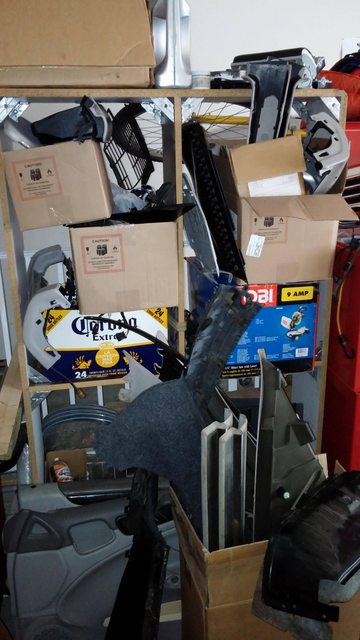
heres's whats removed. I'm thinking weight savings is going to be more than I anticipated:
boxes, 1 2 and 3 are for the garbage:
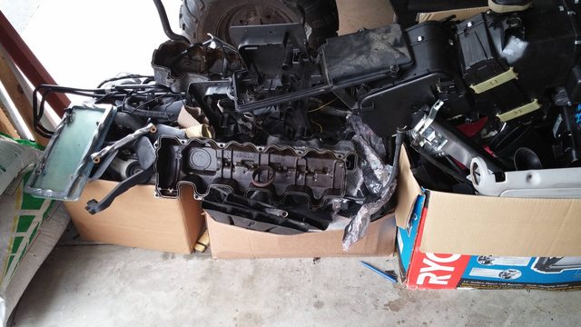
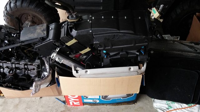
radiators and possibly resellable engine parts:
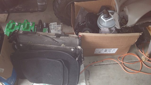
and random boxes with interior panels and ****:
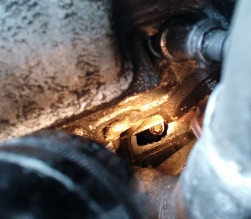
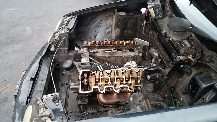
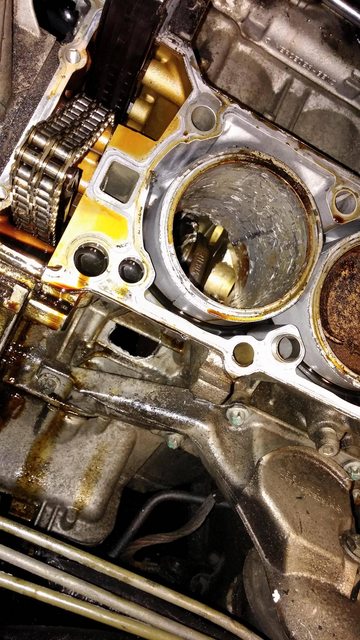
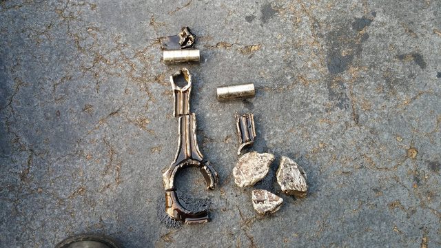
I was bored. Pulled the head off the side that blew up.
THE PISTON IS GONE. like... it doesn't exist anymore.
sweet jeebus....
heres's whats removed. I'm thinking weight savings is going to be more than I anticipated:
boxes, 1 2 and 3 are for the garbage:
radiators and possibly resellable engine parts:
and random boxes with interior panels and ****:
I was bored. Pulled the head off the side that blew up.
THE PISTON IS GONE. like... it doesn't exist anymore.
sweet jeebus....
11-19-2013, 11:08 PM
#6
Honda-Tech Member
Thread Starter
Join Date: Sep 2001
Location: central, nj, usa
Posts: 2,496
Likes: 0
Received 0 Likes
on
0 Posts
Thanks.
Looking for some input:
trying to size wires and fuses now.
fuses first, because that requires more research.
this is color coded and should be easy to understand.
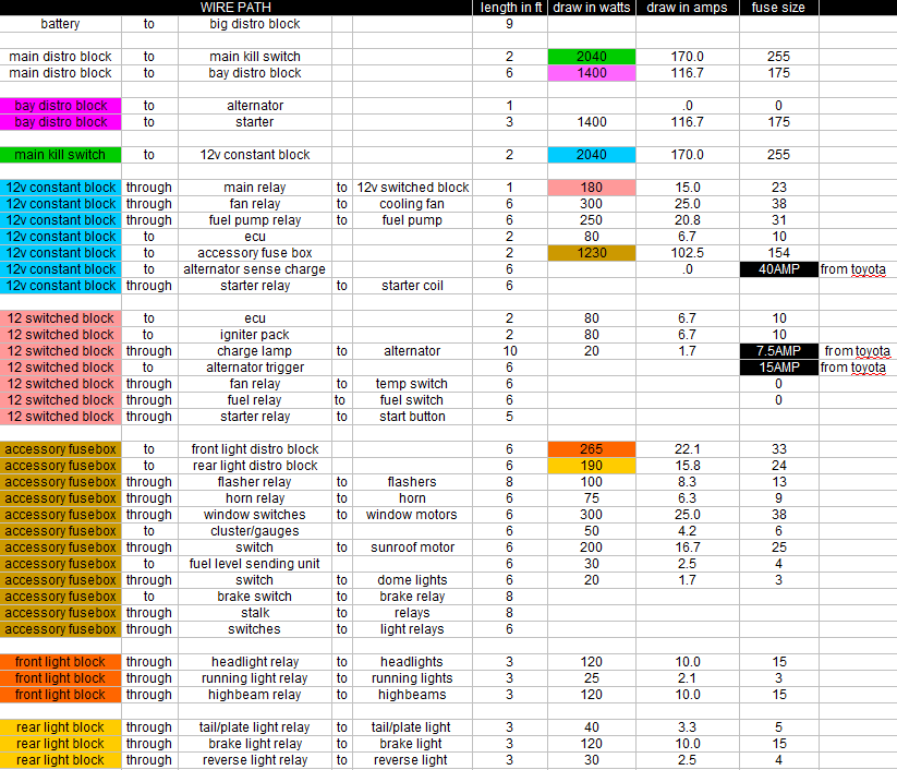
I cant seem to find any information on what size fuses the ECU and Igniter should have. Any ideas?
also for sheilding, is a foil ok, or should i go braided?
once i can figure this out, i'm blowing like $500 on wires, relays, connectors, crimpers, etc.
Looking for some input:
trying to size wires and fuses now.
fuses first, because that requires more research.
this is color coded and should be easy to understand.
I cant seem to find any information on what size fuses the ECU and Igniter should have. Any ideas?
also for sheilding, is a foil ok, or should i go braided?
once i can figure this out, i'm blowing like $500 on wires, relays, connectors, crimpers, etc.
11-21-2013, 12:44 PM
#7
Honda-Tech Member
Thread Starter
Join Date: Sep 2001
Location: central, nj, usa
Posts: 2,496
Likes: 0
Received 0 Likes
on
0 Posts
Exciting day.
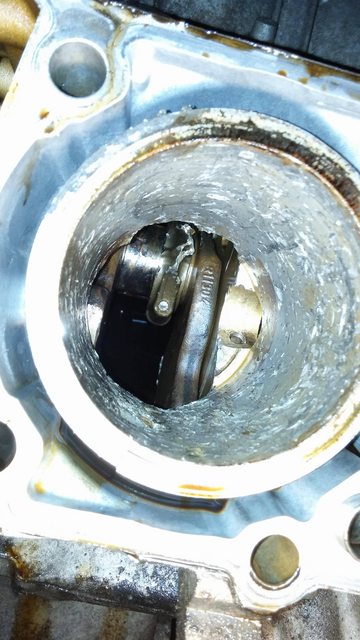
Jammed my arm down the cylinder that was blown up.
Found some engine parts!
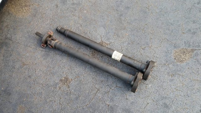
dropped the driveshaft.
finally pulled the engine.
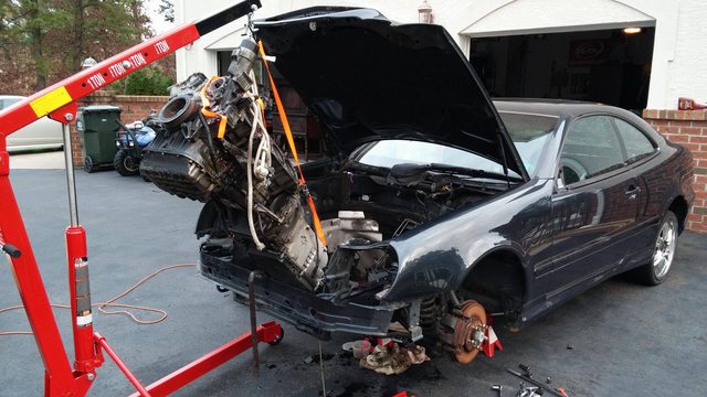
and the obligatory "SO MUCH ROOM FOR ACTIVITIES" photo.

Jammed my arm down the cylinder that was blown up.
Found some engine parts!
dropped the driveshaft.
finally pulled the engine.
and the obligatory "SO MUCH ROOM FOR ACTIVITIES" photo.
Trending Topics
11-23-2013, 05:08 PM
#9
Honda-Tech Member
Thread Starter
Join Date: Sep 2001
Location: central, nj, usa
Posts: 2,496
Likes: 0
Received 0 Likes
on
0 Posts
just got this home:
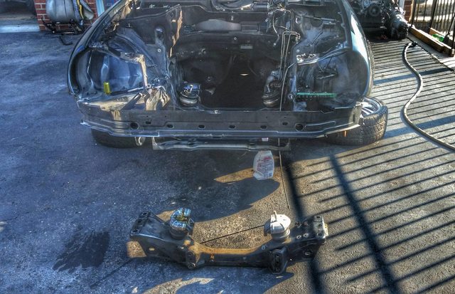
I have mounts already taken care of, but just noticed this:
GS300 Subframe:

my subframe:
Attachment 528434
it's not that easy, but it's neat that it's that close.
I have mounts already taken care of, but just noticed this:
GS300 Subframe:
my subframe:
Attachment 528434
it's not that easy, but it's neat that it's that close.
11-23-2013, 07:51 PM
#11
Honda-Tech Member
Thread Starter
Join Date: Sep 2001
Location: central, nj, usa
Posts: 2,496
Likes: 0
Received 0 Likes
on
0 Posts
i need to talk to someone who knows their ecu info for 2jz's.
Apparently the GE can be boosted, run a JDM VVTI TT ecu and perform like stock.
no clue how accurate that info is, and what year they introduced immobilizers.
Apparently the GE can be boosted, run a JDM VVTI TT ecu and perform like stock.
no clue how accurate that info is, and what year they introduced immobilizers.
11-24-2013, 07:31 PM
#12
Honda-Tech Member
Join Date: Sep 2010
Location: Pensacola, FL and every Court House in Louisiana
Posts: 3,114
Likes: 0
Received 2 Likes
on
2 Posts
Yes the ge block can be boosted with awesome results. Check out NA-T.com. Firt I have ever heard of running a TT ecu and 98% sure it's bogus. Everyone I know running that motor is running a standalone. The vvti block are more difficult to tune than the older non vvti. I have a vvti ge and will be dropping gt motor in its place
11-24-2013, 07:36 PM
#13
Honda-Tech Member
Thread Starter
Join Date: Sep 2001
Location: central, nj, usa
Posts: 2,496
Likes: 0
Received 0 Likes
on
0 Posts
http://www.clublexus.com/forums/sc-4...t-ecu-mod.html
check out the third paragraph:
It's pretty straightforward. The VVTI GT motor was offered in Japan. You stick that ecu to the GE motor with a turbo on it, swap to MAP sensor from MAS, and 440cc injectors. The ecu thinks its running a GT motor with a single on it. Takes piggybacks just like you'd expect.
check out the third paragraph:
If you are 98+ vvti, then you have to use a JDM VVTI 2jzgte ecu but odb2 port will not work. The VVTI 2jzgte was never offered in US.
The 2jzgte vvti and 2jzge vvti have the same ecu connector, but its not the same as non vvti connector, so you are stuck with this ecu but the good news is you already have the right coilpacks ignitor and most of the wiring, and once done it will control vvti like a gte would.
The 2jzgte vvti and 2jzge vvti have the same ecu connector, but its not the same as non vvti connector, so you are stuck with this ecu but the good news is you already have the right coilpacks ignitor and most of the wiring, and once done it will control vvti like a gte would.
12-03-2013, 05:48 PM
#14
Honda-Tech Member
Join Date: Sep 2010
Location: Pensacola, FL and every Court House in Louisiana
Posts: 3,114
Likes: 0
Received 2 Likes
on
2 Posts
http://www.clublexus.com/forums/sc-4...t-ecu-mod.html
check out the third paragraph:
It's pretty straightforward. The VVTI GT motor was offered in Japan. You stick that ecu to the GE motor with a turbo on it, swap to MAP sensor from MAS, and 440cc injectors. The ecu thinks its running a GT motor with a single on it. Takes piggybacks just like you'd expect.
check out the third paragraph:
It's pretty straightforward. The VVTI GT motor was offered in Japan. You stick that ecu to the GE motor with a turbo on it, swap to MAP sensor from MAS, and 440cc injectors. The ecu thinks its running a GT motor with a single on it. Takes piggybacks just like you'd expect.
12-04-2013, 06:56 PM
#16
Honda-Tech Member
Thread Starter
Join Date: Sep 2001
Location: central, nj, usa
Posts: 2,496
Likes: 0
Received 0 Likes
on
0 Posts
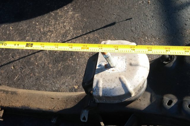
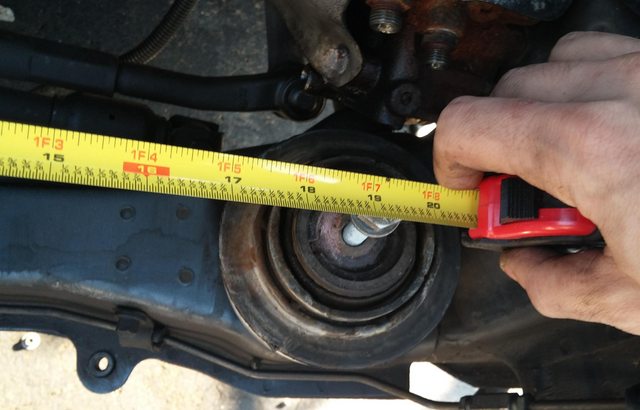
So..... If anyone ever wants to stuff a 2jz into a benz and NOT fab your own motor mounts... you can totally wing it with stock ones.
You need to space the gs300 cast aluminum mounts 1" from the block.
At that point, it should drop onto the benz receiving mounts.
oh, and you can get away with not modding the oil pan. just use the gs300 one,
its front sump and dimpled in the rear to fit over the gs300 crossmember.
gs300 subframe:
benz subframe:
both:
12-12-2013, 06:14 PM
#18
Honda-Tech Member
Join Date: Dec 2004
Posts: 2,949
Likes: 0
Received 0 Likes
on
0 Posts
this has been one of my dream builds. If it had time. Or skills. Or the money to pull it off. So. Not only am i subscribed in H-T you are being bookmarked my good sir.\
Edit: ****! you are local. Sick.
Edit: ****! you are local. Sick.
 12-14-2013, 11:03 PM
#21
"Haters Gonna Hate"
 What he said
 12-15-2013, 03:32 PM
#24
Honda-Tech Member
Thread Starter
Join Date: Sep 2001
Location: central, nj, usa
Posts: 2,496
Likes: 0
Received 0 Likes
on
0 Posts
and here is a brain dump on wiring it all up:
I just needed to get this out of my head and onto paper.
Wrote it in the context of a how-to.
Wiring a 2JZGE VVTI NA-T into *any* chassis.
2JZGE's are cheap.
They handle enough horsepower/boost to have lots of fun.
The VVTI ones are cheaper, as VVTI is a bit of a tuning hassle.
This guide is to put a VVTI GE motor into any chassis, with an aftermarket turbo setup, at lowest cost to you.
Parts needed:
Engine and Harness:
You should be able to find a VVTI motor and harness together, as they were found in a bunch of cars- gs300, is300, sc300, etc. For this purpose a GS300 engine and harness were used.
$300 for long-block and harness seems to be the going rate.
Igniter pack:
Be sure to get the igniter pack (small black box about the size of a deck of cards) that plugs into the engine harness's 10-pin connector. Otherwise, look to spend $50 or so on ebay for a Lexus DH-61. The DS-61 from the Corolla *might* work. It plugs right up and the wiring matches, they sell for about $10. Consider that unconfirmed as of now.
ECU:
You'll be using the ECU from a JDM Aristo. In Japan it came with a 2JZ-GTE VVTI. You want the 89661-3A470 model. It's guaranteed not to have an immobilizer, and your 3 engine harness plugs will snap right in. Expect to spend $100-$200
Injectors:
The Aristo ECU runs 440cc injectors stock. Not 550cc's like US GTE's.
Although 550's should be easily tunable with a fuel controller.
You need top feed injectors and you are looking for high impedance, size = 11mm.
Sensors:
The Aristo uses MAP and AFM to run the ECU. (Use MAF in place of AFM if you'd like)
You *need* to use the Aristo AFM. The AFM is also the IAT sensor, it's part number 22204-46010.
The stock non-turbo AFM is not designed with boost in mind.
When you shut the throttle plate and blow off, the air has to reverse past the sensor.
The sensor doesn't know what reverse flow is, and sees this as more air entering the engine.
In response, your injectors dump fuel. That's bad.
Using the Aristo AFM eliminates this problem.
You need to add a MAP sensor. Use a TT Map sensor. It's 2.3 bar and works fine.
You'll also need this plug: http://store.driftmotion.com/static/...nector3pin.php
and these wires with large seals: http://store.driftmotion.com/static/...iiterminal.php
It must be added to the engine harness you have.
MAP wiring:
pin 1 is brown: Ground
pin 2 is yellow/green: map signal to ecu.
pin 3 is blue/red: +5v from ecu.
Turbo setup:
This is completely up to you. Go look for NA-T setups elsewhere on the internet.
The purpose of all this:
The goal here is to have engine management that will run your NA-T setup. Since we have VVTI, tuning options are a bit tricky. Some aftermarket options have popped up that can manage it, but are out of this project's price range, and power returns often were less than Toyota's OEM tuning.
Put simply, we're tricking the ECU into thinking it's connected to a JDM 2JZGTE VVTI with a single turbo swap. It will manage VVTI like stock. You have an amazing baseline for $100, with endless aftermarket options are available.
The VVTI engine has a great ignition system. The wasted spark setup works fine, and you won't need to change the coils, wires, igniter, etc. With a single turbo setup, the 440cc's have been pushed just past 600hp. They should work fine for the goal at the moment (400hp)
ETCS-i is the trottle system.
There is a tps that connects to the throttle cable from the pedal. This tells the ecu what you want to do.
The ecu responds by using the ETCS-i motor to move the throttle plate. The clutch is used as a safety to disengage the motor in emergency situations. (also involved in limp mode)
There is a final tps on the throttle plate to read what the ETCS-i motor has just done.
Wiring:
The ECU has 5 plugs.
Left to right, they come from engine, engine, engine, body, body.
You have the 3 on your engine harness.
We're going to need to run wires to the body of the car, so you need the plugs for the body.
http://store.driftmotion.com/static/...n22pinvvti.php
http://store.driftmotion.com/static/...n28pinvvti.php
and some wires/terminals:
http://store.driftmotion.com/static/...wire040-ii.php
To operate without going into limp mode or causing any serious problems- the ECU needs the following sensors plugged into the engine/trans:
Plugs 4 and 5 are chassis sub-harness plugs that send the wires to the car. (These are the ones I mentioned purchasing above.)
Between the 2 chassis plugs, you only need to add 9 wires.
Plug 4-
Kill power to pins 8/9/16 on plug 5, and engine it turns off.
As for what's removed from the harness, this is a rough outline-
One of the auto trans plugs matches the speed sensor plug.
The speed sensor you want runs to pins 5 and 11 on plug 3.
Wires on the GS300 harness are Blue/Yellow and Red/Blue.
The TT ecu has different VSV's than the GE ecu and does not control ACIS (secondary butterfly in the intake manifold) correctly when doing the mod. You need to delete the VSV's and take the secondary butterfly that's on the intake manifold and plumb it directly to the manifold. Simply moving the vacuum line solves this problem. Operation is 99% the same this way.
Chassis Plugs: (not the 2 in the ecu, but the ones on the harness)
You'll notice near the ecu plugs, your stock engine harness has white plugs, an orange plug, a black plug, and a black plug with a cover.
These will be removed. The black one with the cap is for diagnostic stuff. Ditch it.
The other connectors have a few wires which we need, other than the 12v and grounds.
Trace them from the following places, and remove them from the connectors. These are the flying leads.
Plug one
Obviously, you want to ground the grounds. Use the intake manifold if the stock location is so.
The 12v wires for injectors/coils/etc need to be connected to the appropriate power sources. Either constant or switched. Covered above.
Alternator sense wire connects as close to your battery + terminal as reasonably possible with a 5a fuse. It's to sense the voltage of the battery, and when charging is needed.
Starter wire is a fat black wire. This connects to 12v through a relay to spin the starter. Trigger the relay with a momentary push-button or cranking position on a key cylinder.
Tachometer output is exactly what it sounds like.
Starter signal/assist wire was covered earlier (plug 4, pin 2)
CEL output goes to a LED or similar, which has it's other side wired to power. When your ECU throws a CEL, the wire from it becomes grounded, in turn lighting up the LED.
Test connector wire needs to be ungrounded. If you throw a CEL, you ground the test connector wire and the CEL will blink, alerting you of the code.
These wires, in combination with any other sensors you add- wideband, aftermarket h20 temp, etc. are what will run into the body of the vehicle.
What else is needed...
The tach output is the only working gauge wire in the flying leads.
The speed sensor only runs to the ecu because it is reportedly required for tps calcuations.
The H20 temp is only read for a similar reason.
I would STRONGLY advise running a full aftermarket gague system.
GPS speedometers are all over the market now. You'll need volt, h2o temp, boots, oil pressure, tach, etc.
Wire these accordingly.
Cooling system also needs addressing. There is no wiring for the radiator cooling fan, or a proper temperature trigger for it. You'll need to source these and wire them accordingly.
The alternator low charge light also needs to be wired to a light on the dashboard.
Notes on OBD wiring-
-Is is not standard OBDII, and will not pass any form of inspection. Uses JODB, a Japanese protocol.
-It uses a OBDII connector but requires a scan tool with protocol ISO 14230.
Work around to get info from the JDM Protocol:
Almost sounds like I know what I'm doing now.
I just needed to get this out of my head and onto paper.
Wrote it in the context of a how-to.
Wiring a 2JZGE VVTI NA-T into *any* chassis.
2JZGE's are cheap.
They handle enough horsepower/boost to have lots of fun.
The VVTI ones are cheaper, as VVTI is a bit of a tuning hassle.
This guide is to put a VVTI GE motor into any chassis, with an aftermarket turbo setup, at lowest cost to you.
Parts needed:
Engine and Harness:
You should be able to find a VVTI motor and harness together, as they were found in a bunch of cars- gs300, is300, sc300, etc. For this purpose a GS300 engine and harness were used.
$300 for long-block and harness seems to be the going rate.
Igniter pack:
Be sure to get the igniter pack (small black box about the size of a deck of cards) that plugs into the engine harness's 10-pin connector. Otherwise, look to spend $50 or so on ebay for a Lexus DH-61. The DS-61 from the Corolla *might* work. It plugs right up and the wiring matches, they sell for about $10. Consider that unconfirmed as of now.
ECU:
You'll be using the ECU from a JDM Aristo. In Japan it came with a 2JZ-GTE VVTI. You want the 89661-3A470 model. It's guaranteed not to have an immobilizer, and your 3 engine harness plugs will snap right in. Expect to spend $100-$200
Injectors:
The Aristo ECU runs 440cc injectors stock. Not 550cc's like US GTE's.
Although 550's should be easily tunable with a fuel controller.
You need top feed injectors and you are looking for high impedance, size = 11mm.
Sensors:
The Aristo uses MAP and AFM to run the ECU. (Use MAF in place of AFM if you'd like)
You *need* to use the Aristo AFM. The AFM is also the IAT sensor, it's part number 22204-46010.
The stock non-turbo AFM is not designed with boost in mind.
When you shut the throttle plate and blow off, the air has to reverse past the sensor.
The sensor doesn't know what reverse flow is, and sees this as more air entering the engine.
In response, your injectors dump fuel. That's bad.
Using the Aristo AFM eliminates this problem.
You need to add a MAP sensor. Use a TT Map sensor. It's 2.3 bar and works fine.
You'll also need this plug: http://store.driftmotion.com/static/...nector3pin.php
and these wires with large seals: http://store.driftmotion.com/static/...iiterminal.php
It must be added to the engine harness you have.
MAP wiring:
pin 1 is brown: Ground
pin 2 is yellow/green: map signal to ecu.
pin 3 is blue/red: +5v from ecu.
Turbo setup:
This is completely up to you. Go look for NA-T setups elsewhere on the internet.
The purpose of all this:
The goal here is to have engine management that will run your NA-T setup. Since we have VVTI, tuning options are a bit tricky. Some aftermarket options have popped up that can manage it, but are out of this project's price range, and power returns often were less than Toyota's OEM tuning.
Put simply, we're tricking the ECU into thinking it's connected to a JDM 2JZGTE VVTI with a single turbo swap. It will manage VVTI like stock. You have an amazing baseline for $100, with endless aftermarket options are available.
The VVTI engine has a great ignition system. The wasted spark setup works fine, and you won't need to change the coils, wires, igniter, etc. With a single turbo setup, the 440cc's have been pushed just past 600hp. They should work fine for the goal at the moment (400hp)
ETCS-i is the trottle system.
There is a tps that connects to the throttle cable from the pedal. This tells the ecu what you want to do.
The ecu responds by using the ETCS-i motor to move the throttle plate. The clutch is used as a safety to disengage the motor in emergency situations. (also involved in limp mode)
There is a final tps on the throttle plate to read what the ETCS-i motor has just done.
Wiring:
The ECU has 5 plugs.
Left to right, they come from engine, engine, engine, body, body.
You have the 3 on your engine harness.
We're going to need to run wires to the body of the car, so you need the plugs for the body.
http://store.driftmotion.com/static/...n22pinvvti.php
http://store.driftmotion.com/static/...n28pinvvti.php
and some wires/terminals:
http://store.driftmotion.com/static/...wire040-ii.php
To operate without going into limp mode or causing any serious problems- the ECU needs the following sensors plugged into the engine/trans:
-6 injector plugs (one for each cylinder, derp)
-3 coil packs (3 coil packs for 6 plugs, standard wasted spark setup)
-1 igniter pack (that little black box mentioned earlier)
-2 knock sensors (front and rear of motor, on intake side)
-3 sensors to the throttle body;
-CAMshaft position sensor (the odd ball sensor near the rear of the fuel rail)
-CRANKshaft position sensor (one hidden behind the alternator)
-MAP sesnor (added by you)
-AFM/IAT sensor (2 sensors in one here)
-ONE O2 sensor (you eliminate 3)
-H20 Temp sensor (not for triggering cooling fan)
-Speed sensor (ties into throttle system, needed)
Most of this is contained in the first 3 engine plugs. -3 coil packs (3 coil packs for 6 plugs, standard wasted spark setup)
-1 igniter pack (that little black box mentioned earlier)
-2 knock sensors (front and rear of motor, on intake side)
-3 sensors to the throttle body;
-1 etcs-i motor & etcs-i saftey clutch (operates the actual butterfly)
-1 tps on throttle plate (detects butterfly position)
-1 tps on throttle linkage (detects pedal position)
-vvti solenoid (the plug near the top intake cam gear)-1 tps on throttle plate (detects butterfly position)
-1 tps on throttle linkage (detects pedal position)
-CAMshaft position sensor (the odd ball sensor near the rear of the fuel rail)
-CRANKshaft position sensor (one hidden behind the alternator)
-MAP sesnor (added by you)
-AFM/IAT sensor (2 sensors in one here)
-ONE O2 sensor (you eliminate 3)
-H20 Temp sensor (not for triggering cooling fan)
-Speed sensor (ties into throttle system, needed)
Plugs 4 and 5 are chassis sub-harness plugs that send the wires to the car. (These are the ones I mentioned purchasing above.)
Between the 2 chassis plugs, you only need to add 9 wires.
Plug 4-
Pin 2 is a starter assist. It goes to the wire that triggers the starter to crank. The ECU detects this and assists in starting situations. When cranking, it should see 12v.
Pin 5 is the test connector. If you connect this wire to ground, the check engine light will flash out codes.
Pin 20 is a tach output.
Plug 5- Pin 5 is the test connector. If you connect this wire to ground, the check engine light will flash out codes.
Pin 20 is a tach output.
Pin 1 is connected to the battery at all times via a 25a fuse. This lets the ECU save info. If you disconnect this, it needs to 'relearn' every time you turn it on.
Pin 7 is connected to the battery at all times via a 15a fuse. This is for power to the ETCS-i system. I assume so the ETCS-i motor can close the throttle when the ecu loses power?
Pins 8, 9 and 16 are connected to the main relay- or a point that is given power when the car/key is ON, but not necessarily running.
Pin 6 is output to the check engine light. The other side of the light should be +12v.
If you're wondering the wires needed to start/stop at this point: Pin 7 is connected to the battery at all times via a 15a fuse. This is for power to the ETCS-i system. I assume so the ETCS-i motor can close the throttle when the ecu loses power?
Pins 8, 9 and 16 are connected to the main relay- or a point that is given power when the car/key is ON, but not necessarily running.
Pin 6 is output to the check engine light. The other side of the light should be +12v.
-There is a single wire that runs to the starter (fat and black, part of the ecu harness)
-Plug 1 has 3 grounds that need to be run to the chassis/battery. Pins 9, 21 and 31.
-Plug 2 has 1 gound that needs to be run to the chassis/battery. Pin 17.
-Plug 5 has 5 wires that go to power. 2 constant, 3 switched.
Give 12v to the starter wire, while the rest have power & ground it will start. -Plug 1 has 3 grounds that need to be run to the chassis/battery. Pins 9, 21 and 31.
-Plug 2 has 1 gound that needs to be run to the chassis/battery. Pin 17.
-Plug 5 has 5 wires that go to power. 2 constant, 3 switched.
Kill power to pins 8/9/16 on plug 5, and engine it turns off.
As for what's removed from the harness, this is a rough outline-
All of the VSV valves. These are the vacuum valves. Explained below.
Remove everything involving the automatic transmission.
Main oil level switch on the oil pan is not needed- it's just for the dummy light. You can leave it.
Main oil pressure switch is not needed- again for a gauge. You can leave it.
AC/PS switches are both removed in my case.
Important to note now: Remove everything involving the automatic transmission.
Main oil level switch on the oil pan is not needed- it's just for the dummy light. You can leave it.
Main oil pressure switch is not needed- again for a gauge. You can leave it.
AC/PS switches are both removed in my case.
One of the auto trans plugs matches the speed sensor plug.
The speed sensor you want runs to pins 5 and 11 on plug 3.
Wires on the GS300 harness are Blue/Yellow and Red/Blue.
The TT ecu has different VSV's than the GE ecu and does not control ACIS (secondary butterfly in the intake manifold) correctly when doing the mod. You need to delete the VSV's and take the secondary butterfly that's on the intake manifold and plumb it directly to the manifold. Simply moving the vacuum line solves this problem. Operation is 99% the same this way.
Chassis Plugs: (not the 2 in the ecu, but the ones on the harness)
You'll notice near the ecu plugs, your stock engine harness has white plugs, an orange plug, a black plug, and a black plug with a cover.
These will be removed. The black one with the cap is for diagnostic stuff. Ditch it.
The other connectors have a few wires which we need, other than the 12v and grounds.
Trace them from the following places, and remove them from the connectors. These are the flying leads.
Plug one
-Comes from alternator- it's a sense wire.
-test connector wire from plug 4
Plug two-test connector wire from plug 4
-Starter wire (fat black wire)
Plug three-tach output from plug 4
-starter signal/crank assist wire
there are more, mostly to power sensors and whatnot. eliminate what doesn't run to an essential sensor. use your brain. -starter signal/crank assist wire
Obviously, you want to ground the grounds. Use the intake manifold if the stock location is so.
The 12v wires for injectors/coils/etc need to be connected to the appropriate power sources. Either constant or switched. Covered above.
Alternator sense wire connects as close to your battery + terminal as reasonably possible with a 5a fuse. It's to sense the voltage of the battery, and when charging is needed.
Starter wire is a fat black wire. This connects to 12v through a relay to spin the starter. Trigger the relay with a momentary push-button or cranking position on a key cylinder.
Tachometer output is exactly what it sounds like.
Starter signal/assist wire was covered earlier (plug 4, pin 2)
CEL output goes to a LED or similar, which has it's other side wired to power. When your ECU throws a CEL, the wire from it becomes grounded, in turn lighting up the LED.
Test connector wire needs to be ungrounded. If you throw a CEL, you ground the test connector wire and the CEL will blink, alerting you of the code.
These wires, in combination with any other sensors you add- wideband, aftermarket h20 temp, etc. are what will run into the body of the vehicle.
What else is needed...
The tach output is the only working gauge wire in the flying leads.
The speed sensor only runs to the ecu because it is reportedly required for tps calcuations.
The H20 temp is only read for a similar reason.
I would STRONGLY advise running a full aftermarket gague system.
GPS speedometers are all over the market now. You'll need volt, h2o temp, boots, oil pressure, tach, etc.
Wire these accordingly.
Cooling system also needs addressing. There is no wiring for the radiator cooling fan, or a proper temperature trigger for it. You'll need to source these and wire them accordingly.
The alternator low charge light also needs to be wired to a light on the dashboard.
Notes on OBD wiring-
-Is is not standard OBDII, and will not pass any form of inspection. Uses JODB, a Japanese protocol.
-It uses a OBDII connector but requires a scan tool with protocol ISO 14230.
Work around to get info from the JDM Protocol:
Buy a ELM327 Bluetooth OBD2 Scanner V1.4 OBDII
Purchase and install Torque Pro on an Android device.
In the vehicle profile of the Torque Pro application add the following line in the VERY ADVANCED ELM327 section- “ATIB 96 \n ATIIA 13 \n ATSH8213F0 \n ATSP4 \n 0100”
You should be able to pull data from the ecu now.Purchase and install Torque Pro on an Android device.
In the vehicle profile of the Torque Pro application add the following line in the VERY ADVANCED ELM327 section- “ATIB 96 \n ATIIA 13 \n ATSH8213F0 \n ATSP4 \n 0100”
Almost sounds like I know what I'm doing now.
12-16-2013, 02:25 PM
#25
Honda-Tech Member
Join Date: Dec 2004
Posts: 2,949
Likes: 0
Received 0 Likes
on
0 Posts
I am actually moving to california at the end of the month but for December I am in the Hamilton/Robbinsville Area
And damn-- i dont even have a JZ and i read that whole thing cause it does sound like you know wtf you are talking about.
And damn-- i dont even have a JZ and i read that whole thing cause it does sound like you know wtf you are talking about.