
wiring question
 05-03-2012, 09:20 AM
#1
Who the fack changed my title?!
Thread Starter
so im starting to put the wiring harness back into my car and was wondering one thing. the 2 wire plug on the back of the d15b2, what do those wires do when you swap a ls block into the car? and it has a 1 wire plug? i included a picture for reference
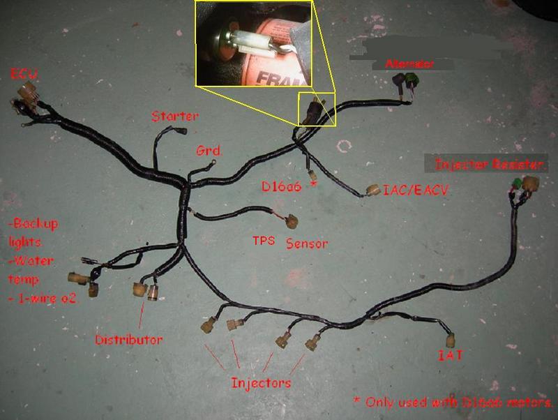
the one in the blown up picture by the oil filter. what do i do? just splice them together and run it to the one plug??
the one in the blown up picture by the oil filter. what do i do? just splice them together and run it to the one plug??
 05-03-2012, 12:12 PM
#7
Who the fack changed my title?!
Thread Starter
ugh you guys are tards lol and so am i for not specifically taking this pic(the one in the middle is what i have currently on the car)

Trending Topics
 05-03-2012, 12:36 PM
#9
Honda-Tech Member
Join Date: Sep 2002
Location: colorado springs, co, usa
Posts: 5,643
Likes: 0
Received 28 Likes
on
28 Posts
the piece with the single pin with green plastic is the oil pressure sending unit - just to the left of that is where the oil temperature sending unit is on the stock B18 - OBD0 B18s had the cooling fan switch just above the oil pressure unit (this is where the big round black boot with yellow/green and black wires connected) - the cooling fan switch on the OBD1 and OBD2 B18 is on the thermostat housing - this is the OBD0:

this is OBD1 cooling fan switch:

this is OBD1 cooling fan switch:
05-03-2012, 12:46 PM
#10
Keyboard Humorist
Join Date: May 2002
Location: Granada Hills, Ca, USA
Posts: 9,814
Likes: 0
Received 9 Likes
on
7 Posts
It would be above the scope of your pic.
Take a pic of your t-stat housing.
Does it look like this with a sensor in it?
If so, then THAT is where the 2 wires go.
It's just a switch so there it's a + / - polarity.
Switch up the wires and it still works.
05-03-2012, 01:28 PM
#11
Who the fack changed my title?!
Thread Starter
ya it was just off the thermostat(the switch) i forgot to switch over the other housing that had one on there so its fixed now.
now the real question. i have the wiring harness all taken apart and i forgot which color wires were ran for the fan switch lol any one care to add in? also need to know which single wire goes to the temp unit on the side of the head...
or screw it if some one can just give me a detailed photo of each plug and what the color combo is and where it goes i would greatly appreciate it!!
05-03-2012, 02:17 PM
#12
Who the fack changed my title?!
Thread Starter
ok took some pix so you all can get a better idea.
the 1st wire is a black wire that was obviously attached to the ground connector


and then i noticed it had this on it

and the one single wire i plugged into the oil press sensor had one on it too! so i assumed these are the correct 2 wires needed for the fan switch

and this is the side of the harness it came off of

but then i ran into this wire before and was soldering it into a new switch assuming it WAS the correct wire of the 2

and it was off of this portion of the harness

on another topic i was wondering if i had these correctly installed in their locations as needed


assuming this one was right

not too sure about this one


here is another that concerns me


and i cannot remember if i had originally set up this for vtak or not but assuming i was

the wires it was attached to

and the connector it came out of

if anyone is kind enough to help id greatly appreciate it!!!
the 1st wire is a black wire that was obviously attached to the ground connector
and then i noticed it had this on it
and the one single wire i plugged into the oil press sensor had one on it too! so i assumed these are the correct 2 wires needed for the fan switch
and this is the side of the harness it came off of
but then i ran into this wire before and was soldering it into a new switch assuming it WAS the correct wire of the 2
and it was off of this portion of the harness
on another topic i was wondering if i had these correctly installed in their locations as needed
assuming this one was right
not too sure about this one
here is another that concerns me
and i cannot remember if i had originally set up this for vtak or not but assuming i was
the wires it was attached to
and the connector it came out of
if anyone is kind enough to help id greatly appreciate it!!!
05-03-2012, 02:36 PM
#13
PHANTOM MENACE
iTrader: (2)
Join Date: May 2005
Location: SYCUAN NINE, CA, USA
Posts: 6,042
Likes: 0
Received 3 Likes
on
3 Posts
You called us tards. I'm no longer kind. 
PS
Pics still don't show up here at work, if no one answers later I'll check back in later at home and see if I can help.
PS
Pics still don't show up here at work, if no one answers later I'll check back in later at home and see if I can help.


 05-03-2012, 04:17 PM
#16
Who the fack changed my title?!
Thread Starter
its actually not as bad as i assumed it would be but just making sure everything is in its correct place is really what im looking to figure out. then the real work will go into effect.
05-03-2012, 05:39 PM
#17
Honda-Tech Member
Join Date: Sep 2002
Location: colorado springs, co, usa
Posts: 5,643
Likes: 0
Received 28 Likes
on
28 Posts
cooling fan switch wires are (1) black and (1) yellow with green stripe - the yellow/green runs from the 14-pin connector at the driver's side firewall to the cooling fan switch and continues on to the cooling fan relay on the passenger side inner fender panel behind the headlight and battery
the one connector that you have plugged into the coolant temp sensor on the end of the head doesn't go there - it appears to have (1) orange and (1) black with yellow stripe - this connector went to the tandem control valve on the DPFI and isn't needed - the connector for the coolant temp sensor on the end of the head should have (1) red with white stripe and (1) green with white stripe
the connector for the IACV appears to be correct - the DPFI IACV had a green connector with (1) black with yellow stripe and (1) blue with yellow stripe
the TPS and MAP sensor wires appear to be correct
the oil pressure sensor has (1) wire, yellow with red stripe
05-03-2012, 06:01 PM
#18
Who the fack changed my title?!
Thread Starter
thank you sooo much! now i know where that one green plug goes thats connected to the green and red wires. that was the coolant temp switch! silly me. its been literally over 3 years since i had touched any of this stuff. but one question i have is, what do i do about that extra yell/green stripe wire? the one that is not being used? after all this is done, i should be ready to run?
05-04-2012, 06:45 AM
#19
Honda-Tech Member
Join Date: Sep 2002
Location: colorado springs, co, usa
Posts: 5,643
Likes: 0
Received 28 Likes
on
28 Posts
the second yellow/green wire that comes off the rectangular connector on the passenger side should go to the radiator fan relay which is on the passenger side inner fender panel - the radiator fan relay has 4 wires - 1 black, ground; 1 blue, goes to fan motor; 1 black with yellow stripe, power from fuse 15 in underdash fuse box; 1 yellow with green stripe, from ECU and cooling fan switch - this wire is just a continuation of the yellow/green on the driver's side of the car - the yellow/green in the engine harness, that plugs into the cooling fan switch, runs to the driver's side (on the DPFI cars) connector to the chassis harness - it runs in the chassis harness and connects to the ECU at pin B8 and branches off inside the harness to the rectangular connector on the passenger side - from there it goes to the radiator fan relay

05-08-2012, 08:23 AM
#21
Honda-Tech Member
Join Date: Sep 2002
Location: colorado springs, co, usa
Posts: 5,643
Likes: 0
Received 28 Likes
on
28 Posts
the white wire in the 14 pin driver's side connector is for the igniter in the distributor - the white wire in the 14 pin passenger side connector is for the crank sensor in the distributor
05-08-2012, 09:18 AM
#22
Honda-Tech Member
Your harness needs a lot of work.
Yellow/green fan switch wire should only go to drier side plug. The one on passenger plug is for water temp
Yellow/green fan switch wire should only go to drier side plug. The one on passenger plug is for water temp
05-08-2012, 09:19 AM
#23
Honda-Tech Member
The plug with the orange wire and black/yellow wire is NOT used on an mpfi car. That is from the tandem valve on the DPFI set up. So remove it. Since your harness is already opened up I would simply depin and remove it completely
05-10-2012, 03:02 PM
#25
Who the fack changed my title?!
Thread Starter
cool. i really appreciate all the help you guys are giving me. i sit there at times and just stare at the rats nest of wires i have and don't know where to begin lol. ill update talk with more updates as i make more progress. and assuming i can depin the ignitor wire since the jumper harness already has wires wired to the dizzy.

