When you click on links to various merchants on this site and make a purchase, this can result in this site earning a commission. Affiliate programs and affiliations include, but are not limited to, the eBay Partner Network.
Will need to pick up some starter fluid when roommate gets home from work. In the meantime, I think I may have found the source of my electrical problems: the big rubber grommet under the fuel filter was 2-3 inches from its home on the firewall. A giant bundle of wires passes through that hole and they were just rubbing on bare metal.
Will need to pick up some starter fluid when roommate gets home from work. In the meantime, I think I may have found the source of my electrical problems: the big rubber grommet under the fuel filter was 2-3 inches from its home on the firewall. A giant bundle of wires passes through that hole and they were just rubbing on bare metal.
There ya go
Pick up some heat shrink tubing and corrugated tubing to insulate and protect the wires.
Best way to get at those wires? I think I can disconnect 6 or 8 plugs near main fuse box n feed everything into cabin and work there. Is it possible to disconnect something inside and do the reverse?
Best way to get at those wires? I think I can disconnect 6 or 8 plugs near main fuse box n feed everything into cabin and work there. Is it possible to disconnect something inside and do the reverse?
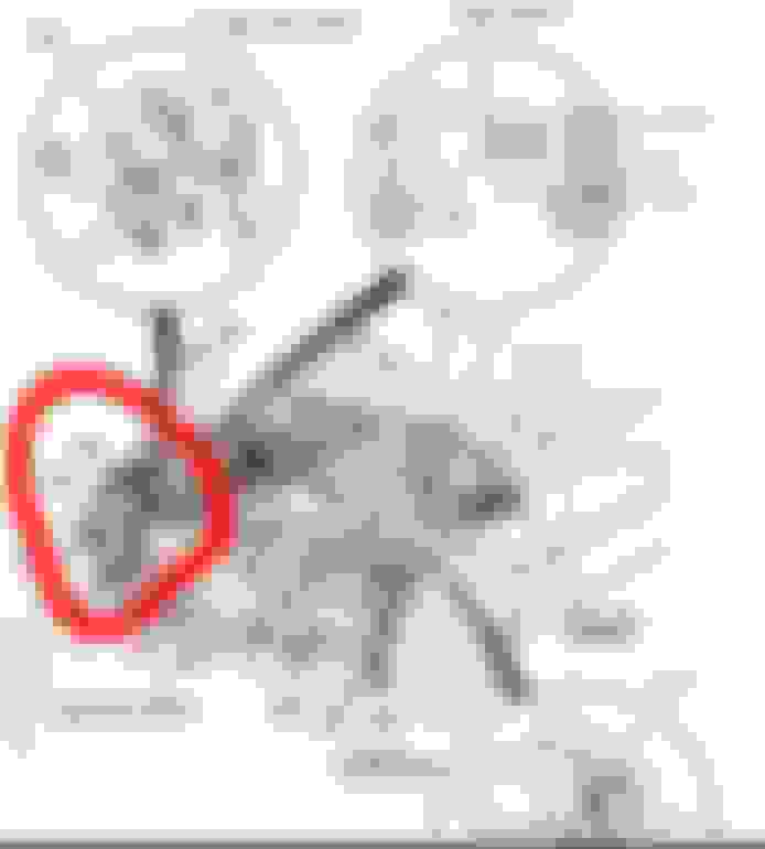
Ok here is the general area where I think my electrical problems are likely to be:
and here is the best closeup I can get. I think you should be able to see that the grommet isn't in place and wires are just rubbing metal:
I can actually see this area a lil better than my phone can, but can't really get close enough to inspect individual wires, much less repair them.
Here is the view from the other side of the firewall (passenger side floorboard):
In that shot, I have pulled back the carpet, removed ECU, it's cover plate, and there is another rubbery mat I'm just holding up to get that shot. Camera can see this side alot better than I can.
My first thought is to remove these 8 connectors in the engine bay, feed everything into the cabin, and make my repairs:
But plugs 5 and 6 look awfully big, like they might not even fit through. I'm not seeing any other way from these two angles, but I haven't researched that much either. Will my plan work? Is there a better one I'm not seeing?
Start by removing the charcoal canister (two vacuum hoses and an electrical connector connected to cannister and then canister). This should open your field of view and increase the working space.
Not sure, but you may be able to save yourself a lot of time by doing the wire repairs in the engine bay after removal of the air intake and EVAP canister.
Ugh, didn't notice this whole chunk of that harness:
This certainly complicates my plan of attack. I think I'm gonna have to find some slack SOMEWHERE to be able to work on those wires. Will let yall know what I figure out. Thanks again, muellersfan!
Don't panic. You'll likely find a convenient way to access and repair the wires. My guess is that after removal of the intake and canister, you'll be able to access the damaged harness from below the car raised on stands.
The 6th generation Civic engine and main wire harnesses are much more logically arranged and accessible than your 4th generation Civic.
Bet you guys can figure out what I had to do just from that pic. Tried Inspecting from above, and knew that even if I saw the problem, I'd never be able to fix it. Threw her up on jack stands, and the subframe is just below the hole, and right in my way. So now the entire passenger-side harness is inside the cabin:
Was hoping the problem would be obvious once I got to this point, but it is not. I have a couple hours before sunset, will check back with you guys then.
Combed through those wires a couple hours last night, and again this morning. Pretty confident that everything is fine so I loomed it all back up and returned all the passenger side connectors to their homes. Pulled the dash today, looking for anything suspect. So far the only thing I've seen that looks fishy is this tattered wire on top right corner of interior fuse box:
Looks like maybe a ground wire that deteriorated years ago?
You're now on a wild goose chase. Refocus on no-start diagnostic tests, such as spraying starting fluid into the TB and checking for spark at the plugs.
Tested spark early on with a test light clipped to ground, the probe end shoved in each plug wire, and a buddy of mine cranking the engine: she passed. When I inspected the plugs, there was a bit of concern, plugs 1 & 4 had a little oil in there. Back in February or March, I replaced the valve cover gasket and the 4 easy gaskets on top of the spark plug tubes, but the gasket set also came with a few rings and a figure-eight shaped gasket that go under the cam. I wasn't up for replacing those, and I'm sure that's why oil is able to creep up into the tubes. It isn't much, and I intend to remedy that soon, but I would rather not open up the head at this time, especially with a known break in the wiring. Do you think those oily plugs could be the source of my problems?
As for starting fluid in throttle body test, are any of these things an acceptable substitute for starting fluid? I have some Brakleen, Throttle body cleaner and WD40. Another concern is that the dash is out at the moment, will these lil hondas run without those gauges plugged in?
I thought this test upthread confirmed a break in YEL/BLK wire?
Originally Posted by muellersfan
Temporary test fix:
Cut both Yel/Blk wires at the pierce point and splice to long new wires of the same gauge.
Cut Yel/Blk wires that run to A13 and A15 (~2 inches from ECU connector).
Cut Yel/Blk wire that runs to injector resistors, also leaving ~2 inches of wire.
Run one of the two new main relay wires to the ECU and splice to the cut A13 and A15 wires and the other to injector resistors and splice to cut wire.
Install main relay and ECU connectors.
Does engine now start and run?
Originally Posted by muellersfan
Once I bypassed that wire and the car didn't start, I figured there must be multiple broken wires? I guess it could be anything really, but with one confirmed open in the electrics, I thought it best to find that problem and inspect the other wires near it. I've been searching for damaged wires the last few days and haven't found anything. That big bundle of wires that passes through the firewall on the passenger side ended up having no YEL/BLK wires in it, but after seeing that grommet out of place and having a confirmed broken wire in the system, I felt it HAD to be inspected before moving on.
Today I checked continuity on the stock wires between main relay and ECU pins A13 and A15, and both checked out miraculously even though I had repaired nothing. I also saw 2 YEL/BLK wires at what I believe to be connector C313, (it is right by resistor box, and has 14 spots for pins, only 12 used). I had continuity from main relay to one of the two YEL/BLK pins there. I thought, "hey 3 out of 4 ain't bad, maybe that 4th one is non-critical". So I decided to take a chance, soldered all my wires back to stock, put the dash back in, along with a new main relay (cheapo $12 chinese one, not the Japanese Mitsubas I've been switching in and out this whole time), and gave her a shot. No luck, I'm back to my original problem: No start, no power at injectors. It looks to me like that 4th YEL/BLK wire needs further attention, That section of the harness enters the cabin just under the fuel return line and the clutch cable. I'd feed it back through and inspect like I did the other side but things are even more cramped on the driver side. I couldn't even see that hole when the dash was removed (might take a 90 towards the fender?). Can I take the "good" YEL/BLK wire at that connector and just splice both pins to the one wire?
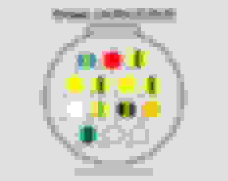
Upon further inspection, the monotech engine harness only uses one of those two power feeds (the one that is broken of course). The "good" YEL/BLK is capped on the other side of the connector. My lil hook tool is pointed to the empty pin where power will flow. Think I'll just swap those pins if I can figure out how to depin em. Seems Honda gave me a backup wire? Or should these two wires be doing 2 different things?
Upon further inspection, the monotech engine harness only uses one of those two power feeds (the one that is broken of course). The "good" YEL/BLK is capped on the other side of the connector. My lil hook tool is pointed to the empty pin where power will flow. Think I'll just swap those pins if I can figure out how to depin em. Seems Honda gave me a backup wire? Or should these two wires be doing 2 different things?
I dont know what I'm doing here... I have just enough knowledge of circuits to make a light bulb work, and I have also successfully wired a few relays into my other vehicles, but when wires enter an ECU, or disappear into the dash where I can't trace em, the whole electrical system kinda becomes "magic" to me. I stared at that main relay diagram forever and just can't figure out what is going on in there, they describe it as "contains 2 individual relays", but it looks far more complicated to me. I really appreciate your patience with me muellersfan, I'm trying to learn.
So it's good that only one of those two YEL/BLK wires on main harness has power? I assumed both should be energized when key was in "on" position. The one WITHOUT power has continuity to resistor box and then resistors. It appears to me that the one WITH power has nothing coming out of the opposite connector on the engine harness side. I saw that, and figured I could just swap them, completing the connection from relay to resistors. But yeah, I don't really understand what is going on. I see 3 YEL/BLK wires at main relay, connected to 2 pins. Somehow there are 2 at ECU and 2 more at that 14pin plug. No idea how those 3 wires became 4. Then it looks to me like the engine harness only uses 1 of the 2 YEL/BLK wires at that plug. Seemed almost like a spare was routed just for this situation? Idk, electricity and wiring hurts my brain.
OK, not guaranteeing I haven't made a mistake, but here's my notes from when I did my DPFI to MPFI conversion last year on my 90 DX Sedan
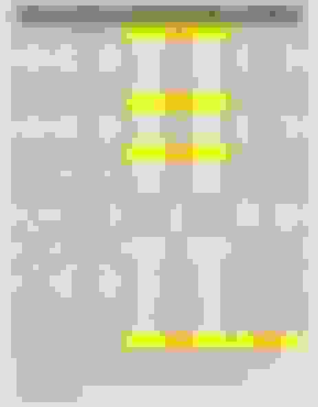
These first two pictures show the 14-pin driver's side connector, engine harness side of the connector and where the wires go in a stock / DPFI configuration. Some of the function abbreviations are: AUX = auxiliary injector, INJ = main injector, AT = auto trans lockup solenoid, TND = tandem valve.
These next two pictures show the 14-pin driver's side connector, chassis harness side of the connector and where the wires go in a stock / DPFI configuration. Some of the function abbreviations are:
So, I'm not sure how Monotech wires their harness - I did my own. However, on a stock / DPFI harness, the pin you are pointing to with your hook would be the +12V power that would be supplied to the EACV. I would think the YEL/BLK wire directly to the right of the 'hook tool' in your picture would be the +12V for the injectors coming into the engine harness. This wire should show continuity from the 14-pin connector to the only YEL/BLK wire at the resistor box connector. The four RED/BLK wires at the resistor box connector should each individually show continuity to the RED/BLK wires at each of the four injectors.
The MPFI engine does not use the Tandem Air Valve, which was a component on the DPFI intake manifold that needed a +12V power supply. Maybe the 'unused' +12V is the one that was for it?
The images above are screenshots from the excel file attached here. One HUGE caveat if you look at the excel file is this: these are my notes from my build, which worked for me. My car is a 90 Civic DX Sedan that was automatic and converted to a 5-speed. Your mileage may vary. I may have some typos. Do your own research. I was going to do a big writeup with pictures and explanations, but I felt like it just got too wordy and hard to explain, so I gave up. Some things on this are incomplete. I did some things that may seem weird or way different than other folks would have done, but whatever, my car runs. If you're fine with all of that, go ahead and take a look. It may help, it may not.
DaX's post provide three candidates for the Yel/Blk wire lacking voltage - main injector (12V), auxiliary injector (12V), and IACV.
1) You can rule out the IACV as a problem because IACV code 14 is not thrown.
2) MPFI does not require the auxiliary injector.
3) You already ran a new wire for the MPFI injectors (12V), so they now have power.
Do you still have voltage at ECU A13 and A15? If so, move forward with the no-start diagnostic tests.
OK, not guaranteeing I haven't made a mistake, but here's my notes from when I did my DPFI to MPFI conversion last year on my 90 DX Sedan
These first two pictures show the 14-pin driver's side connector, engine harness side of the connector and where the wires go in a stock / DPFI configuration. Some of the function abbreviations are: AUX = auxiliary injector, INJ = main injector, AT = auto trans lockup solenoid, TND = tandem valve.
OK, My monotech harness is almost the same as this diagram, only a couple differences:
1) mine has a solid blue wire in pin 8, the one that went to tandem valve. I believe TND was only for dpfi? I'm not sure where monotech runs this one, I didn't see any solid blue wires at the connectors, but about half of them are shrinkwrapped at or very close to their connectors. I can definitely track this one down with a multimeter, but haven't done so yet.
2) I have a GRN/BLK wire at pin 14. I believe this one runs to my backup sensor.
3) pin4 is not used in the monotech harness
4) It may be worth noting here that I have 2 YEL/BLK wires coming from pin6. pin6 is one of 4 pins tied to my injectors.
At Injector #1, I have continuity to pins 1,2,5, and 6 in plug C122
At Injector #2, I have continuity to pins 1,5 and 6
At Injector #3, I have continuity to pins 1,2,5, and 6
At Injector #4, I have continuity to pins 1,2 and 6
Originally Posted by DaX
These next two pictures show the 14-pin driver's side connector, chassis harness side of the connector and where the wires go in a stock / DPFI configuration. Some of the function abbreviations are:
My C313 plug is setup exactly like @DaX 's diagram above. With help from @muellersfan , I was able to confirm that my car has problems between this plug and the main relay. I'm not sure how many pins should be energized with key in "on" position, but I get 12 volts at pins 4, 7, 9 and 10 only. none of the pins that are tied to injectors get power. I also get .12 volts (notice the decimal) at pin 3.
Since pin 4 has 12v at chassis harness, and is unused by monotech harness, I'd like to send that power to all the pins that need it and see if she runs. Which ones should get the juice?
After the MPFI swap, the following things need +12V supplies:
EACV - This controls your idle, and you'll likely get a CEL if it's not getting the voltage it needs. Resistor box - this distributes the +12V to the four injectors. The resistor box plug should be a 6-pin plug with 5 wires - one +12V in, and four wires that run one to each injector. Reverse lights - my car was originally an auto, so the reverse lights weren't in the engine harness, and instead were at the shifter. When I converted to manual, I had to run my own reverse lights. Not sure where the stock location is for this in the harness. Alternator - this comes from C102 (on my car it is BLK/YEL), which is the big 8-pin connector with the dielectric grease in it and the plastic boot around it that is located on the passenger shock tower. Distributor - this comes from C102 also, and is also BLK/YEL.
It doesn't really matter where it comes from - if you make sure each of these things has the +12V (switched) that they need, you should be good...unless the problem lies elsewhere.
I'm not sure if you missed it since I posted it with the pictures (or if it will even help), but I did post the Microsoft Excel file that the screenshots were pulled from. Each tab on the sheet covers the engine and chassis harnesses before and after the MPFI swap, and a separate tab where I tried to break down what all I did, step by step.

 10-31-2018, 12:10 PM