
D.I.Y. / FAQ - OBD-0 --> OBD-1 Pinouts and Conversion Help
 07-24-2013, 06:39 PM
#226
Honda-Tech Member

Join Date: Oct 2012
Posts: 41
Likes: 0
Received 0 Likes
on
0 Posts
Ok gents, so hears is my clusterfuck update.
So I traced the wires on the injectors. These injectors are obd1 from the gsr.
ENGINE SIDE
Injector #1: Goes to the 14 pin ECU plug/to resistor box
Injector #2: Shock tower big plug/ resistor box
Injector #3: Goes to 14 pin ECU plug/ resistor box
Injector #4: Goes to Shock tower big plug/ resistor box
So as per the DPFI to MPFI write up, I'm seriously confused. There is no mention of the shock tower plug at all.
From my understanding, I need to run 4 wires for each injector directly to ECU pins A1,A3,A5,A7, then separately run another 4 into the resistor box.
Another kerfuffle is inside the car, where the plug runs from the ECU, here is the pinout as I have traced it.
14 pin plug ECU side
1 2 3
4 5 6 7
8 9 10 11
12 1314
1:unattached wire for now
2:unattached wire for now
3:unattached wire for now
4:empty slot
5:empty slot
6:unattached wire for now
7:Wire goes to ECU pin injector #2
8:Empty
9:unattached wire for now
10:unattached wire for now
11: Wire runs to ECU pin injector #4
12:Cylinder position sensor ground
13:Cylinder position sensor
14:unattached wire for now
For this same 14 pin connector engine side
1 2 3
4 5 6 7
8 9 10 11
12 1314
1:VTEC pressure switch wire 1
2:VSS wire 1
3:VSS wire 2
4:Injector #4
5:VTEC pressure switch wire 2
6:VSS wire 3
7:Unattached wire
8:Injector #2
9:Unattached wire
10:Unattached wire
11:Unattached wire
12: VTEC solenoid wire
13: Cyl position sensor
14: Cyl position sensor ground
Last edited by Mekk82; 07-25-2013 at 09:12 AM.
 07-25-2013, 09:12 AM
#227
Keyboard Humorist
Join Date: May 2002
Location: Granada Hills, Ca, USA
Posts: 9,814
Likes: 0
Received 9 Likes
on
7 Posts
The ECU supplies each injector with a GROUND pulse.
The resistor box supplies each injector with constant POSITIVE voltage.
The resistor box supplies each injector with constant POSITIVE voltage.
07-25-2013, 09:37 AM
#228
Honda-Tech Member
Join Date: Oct 2012
Posts: 41
Likes: 0
Received 0 Likes
on
0 Posts
I think that's where i'm lost.
I'm going to pull the wires from the plug that should be running directly to the ecu and pin them correct pins and see what occurs.
07-25-2013, 10:03 AM
#229
Keyboard Humorist
Join Date: May 2002
Location: Granada Hills, Ca, USA
Posts: 9,814
Likes: 0
Received 9 Likes
on
7 Posts
More than likely you won't find show tower pinouts.
The wire colors basically match on both sides.
This is some image I found on Google -
Notice how the connector is called out, but not the location of each wire in the connector.
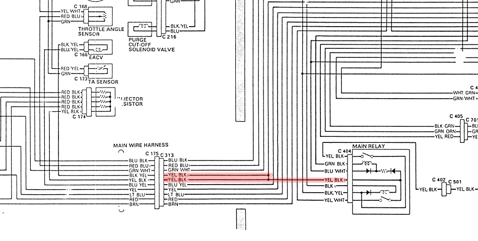
Your 2 DPFI injectors both should have ran through the passenger side shock tower plug.
Just check for the color at the plug and then test for continuity to the other end of the wire at the ECU.
The main relay sends the positive power to the injectors when you turn your ignition key.
I think that went into the plug on the driver side.
Honestly, it doesn't matter where in the firewall connector the wires go.
Just as long as the wire matches up on the engine harness when you plug it in.
- WHY/HOW -
How do you have vtec and VSS wires on your engine harness?
They do NOT exist on the stock DPFI harness.
Sounds like you are in for some ... ummm... fun???!?!
You are supposed to be using your stock DPFI engine harness and converting it to MPFI.
Really easy to do.
However, now it seems like you have a different engine harness for a MPFI engine that has VTEC - NOT your stock DPFI engine harness.
- GOOD LUCK TRYING TO WIRE THAT -
The wire colors basically match on both sides.
This is some image I found on Google -
Notice how the connector is called out, but not the location of each wire in the connector.
Your 2 DPFI injectors both should have ran through the passenger side shock tower plug.
Just check for the color at the plug and then test for continuity to the other end of the wire at the ECU.
The main relay sends the positive power to the injectors when you turn your ignition key.
I think that went into the plug on the driver side.
Honestly, it doesn't matter where in the firewall connector the wires go.
Just as long as the wire matches up on the engine harness when you plug it in.
- WHY/HOW -
How do you have vtec and VSS wires on your engine harness?
They do NOT exist on the stock DPFI harness.
Sounds like you are in for some ... ummm... fun???!?!
You are supposed to be using your stock DPFI engine harness and converting it to MPFI.
Really easy to do.
However, now it seems like you have a different engine harness for a MPFI engine that has VTEC - NOT your stock DPFI engine harness.
- GOOD LUCK TRYING TO WIRE THAT -
07-25-2013, 10:21 AM
#230
Honda-Tech Member
Join Date: Oct 2012
Posts: 41
Likes: 0
Received 0 Likes
on
0 Posts
More than likely you won't find show tower pinouts.
The wire colors basically match on both sides.
This is some image I found on Google -
Notice how the connector is called out, but not the location of each wire in the connector.

Your 2 DPFI injectors both should have ran through the passenger side shock tower plug.
Just check for the color at the plug and then test for continuity to the other end of the wire at the ECU.
The main relay sends the positive power to the injectors when you turn your ignition key.
I think that went into the plug on the driver side.
Honestly, it doesn't matter where in the firewall connector the wires go.
Just as long as the wire matches up on the engine harness when you plug it in.
- WHY/HOW -
How do you have vtec and VSS wires on your engine harness?
They do NOT exist on the stock DPFI harness.
Sounds like you are in for some ... ummm... fun???!?!
You are supposed to be using your stock DPFI engine harness and converting it to MPFI.
Really easy to do.
However, now it seems like you have a different engine harness for a MPFI engine that has VTEC - NOT your stock DPFI engine harness.
- GOOD LUCK TRYING TO WIRE THAT -
The wire colors basically match on both sides.
This is some image I found on Google -
Notice how the connector is called out, but not the location of each wire in the connector.
Your 2 DPFI injectors both should have ran through the passenger side shock tower plug.
Just check for the color at the plug and then test for continuity to the other end of the wire at the ECU.
The main relay sends the positive power to the injectors when you turn your ignition key.
I think that went into the plug on the driver side.
Honestly, it doesn't matter where in the firewall connector the wires go.
Just as long as the wire matches up on the engine harness when you plug it in.
- WHY/HOW -
How do you have vtec and VSS wires on your engine harness?
They do NOT exist on the stock DPFI harness.
Sounds like you are in for some ... ummm... fun???!?!
You are supposed to be using your stock DPFI engine harness and converting it to MPFI.
Really easy to do.
However, now it seems like you have a different engine harness for a MPFI engine that has VTEC - NOT your stock DPFI engine harness.
- GOOD LUCK TRYING TO WIRE THAT -
The engine harness remains stock, with GSR specific sensors added into it, such as at the dizzy. and this ECU connector..From the ecu plugs I have an obd0-obd1 conversion harness to plug into the chipped P28.
07-25-2013, 06:52 PM
#231
Honda-Tech Member
Join Date: Oct 2012
Posts: 41
Likes: 0
Received 0 Likes
on
0 Posts
Small update, I checked the injectors for voltage, and they are all putting out 12-13v steady with the key in "on" position. This leads me to think my culprit may be the distributor.
Will update as I progress.
Will update as I progress.
08-07-2013, 05:35 PM
#233
Honda-Tech Member
Join Date: Oct 2012
Posts: 41
Likes: 0
Received 0 Likes
on
0 Posts
Another small update. Car runs, albeit in limp mode but its a step forward.
Currently I am going to wire up VTEC, VSS to the ecu. My question concerns my 0bd0-0bd1 jumper harness, which looks like this:
For wiring up VTEC/ IAB/ VSS for the B18c, I noticed that not all locations on my jumper harness were open.. pin A17 for example, already has a wire in that spot. Or A4 as well, in this case, do I splice the wires for the VTEC solenoid into the existing wires or depin them?
Secondly, I am not sure what gen of jumper harness I have, when I did my DPFI to MPFI conversion, I switched the TPS wires as instructed, is there a chance the jumper harness has already been wired up to accommodate that difference meaning I should switch the wires back to their original position?
Thanks!
08-08-2015, 02:45 PM
#235
Honda-Tech Member

Join Date: Jul 2015
Posts: 17
Likes: 0
Received 0 Likes
on
0 Posts

You have diy harness info still?
I'm making harness for my 91 dx running lsvtec on a vtec converted p75. completely from scratch. Well from a couple old da harnesses and what's left after the flames that were under kick panel, previous wiring expert must have bought his cert at walmart. Last week I have gotten about three quarters of the way through building a harness and includes interior and Bay convert in my own P 75 to p 72 as well as building a good obd1 distributor out of about five others there's a lot to go wrong here if not using some good quality information to do so anything you can give me to help the situation would be very much appreciated
05-18-2017, 09:15 PM
#236

Join Date: May 2017
Posts: 1
Likes: 0
Received 0 Likes
on
0 Posts
This is what I have established so far from an MPFI OBD-0 to OBD-1 wiring harness jumper. I will figure out OBD-1 ECU to OBD-0 chassis in a bit, I.E wires that have to be run back into the engine.
CORRECTIONS ARE WELCOME UPDATE #10
KEY
XXXXXXXXXXXX Not Used
?????????????? What Goes here?
OBD-0 OBD-1 HARNESS CONNECTIONS: PROOF-READ BY TURBOGIXXER
Further assistance and commentary by vtecn8ive
Thanks to sanimalp for converting this table to vBulletin format
A01 - INJ #1 A01 - INJ #1
A02 - PG1 A23 - PG1
A03 - INJ #2 A03 - INJ #2
A04 - PG2 A24 - PG2
A05 - INJ #3 A05 - INJ #3
A06 - PCS A20 - PCS
A07 - INJ #4 A02 - INJ #4
A08 - LOCKSOL XXXXXXXXXXX
A09 - NOTUSED XXXXXXXXXXXX
A10 - EGR CSV A11
A11 - IACV A09 - IACV
A12 - FLR1 A07 - FLR1
A13 - IGP1 A25 - IGP1
A14 - FLR2 A08 - FLR2
A15 - IGP2 B01 - IGP2
A16 - GRD A26 - LG1
A17 - NOTUSED XXXXXXXXXXXX
A18 - GRD B02 - LG2
B01 - VBP D01 - VBU
B02 - NOTUSED XXXXXXXXXXXX
B03 - ACC A15 - ACC
B04 - FANC A12 - FANC
B05 - ALT A16 - ALT
B06 - MIL A13 - MIL
B07 - NOTUSED XXXXXXXXXXXX
B08 - ACS B05 - ACS
B09 - NOTUSED XXXXXXXXXXXX
B10 - CYP P B11 - CYP P
B11 - FUSEBOX xxxxxxxxxxxx
B12 - CYP M B12 - CYP M
B13 - FUSEBOX B09 - STARTER
B14 - ALT D09 - ALT
B15 - Igniti A21 - ICM
B16 - VSS B10 - VSS
B17 - Igniti A22 - ICM
B18 - NOTUSED XXXXXXXXXXXX
B19 - ELD D10 - ELD
B20 - SCS D04 - SCS
C01 - CKP P B15 - CKP P
C02 - CKP M B16 - CKP M
C03 - TDC P B13 - TDC P
C04 - TDC M B14 - TDC M
C05 - IAT D15 - IAT
C06 - ECT D13 - ECT
C07 - TPS D11 - TPS
C08 - EGR VLS D12
C09 - PA NOTUSEDXXXXX
C10 - BKSW D02 - BKSW
C11 - MILGRND D17 - MAP
C12 - SG2 D22 - SG2
C13 - VCC1 D19 - VCC1
C14 - SG1 D21 - SG1
C15 - VCC2 D20 - VCC2
C16 - O2S D14 - PHO2S
OBD-1 OBD-0 ECU CONNECTIONS
A01 - INJ #1 A01 - INJ #1
A02 - INJ #4 A07 - INJ #4
A03 - INJ #2 A03 - INJ #2
A04 - VTEC RUN TO ENGINE BAY
A05 - INJ #3 A05 - INJ #3
A06 - PO2SHTC RUN TO ENGINE BAY
A07 - FLR1 A12 - FLR1
A08 - FLR2 A14 - FLR2
A09 - IACV A11 - IACV
A10 - NOTUSED XXXXXXXXXX
A11 - EGR CSV A10 - EGR CSV
A12 - FANC B04 - FANC
A13 - MIL BO6 - MIL
A14 - NOTUSED XXXXXXXXXX
A15 - ACC B03 - ACC
A16 - ALT B05 - ALT
A17 - IAB CS RUN TO ENGINE BAY (B18C1 Only)
A18 - NOTUSED XXXXXXXXXX
A19 - FAS RUN TO ENGINE BAY (AUTO TRANSMISSION ONLY)
A20 - PCS A06 - PCS
A21 - ICM B15 - IGNITION
A22 - ICM B17 - IGNITION
A23 - PG1 A02 - PG1
A24 - PG2 A04 - PG2
A25 - IGP1 A13 - IGP1
A26 - LG1 A16 - GRD
B01 - IGP2 A15 - IGP2
B02 - LG2 A18 - GRD
B03 - AFSA RUN TO ENGINE BAY (AUTO TRANSMISSION ONLY)
B04 - AFSB RUN TO ENGINE BAY (AUTO TRANSMISSION ONLY)
B05 - ACS B08 ACS
B06 - NOTUSED XXXXXXXXXX
B07 - ATP PN RUN TO ENGINE BAY (AUTO TRANSMISSION ONLY)
B08 - PSPSW Power steering Load - HARDWIRE (PS ONLY)
B09 - STS B13 - FUSEBOX
B10 - VSS B16 - VSS
B11 - CYP P B10 - CYP P
B12 - CYP M B12 - CYP M
B13 - TDC P C03 - TDC P
B14 - TDC M C04 - TDC M
B15 - CKP P C01 - CKP P
B16 - CKP M C02 - CKP M
D01 - VBU B01 - VBP
D02 - BKSW C10 - BKSW
D03 - KS RUN TO ENGINE BAY (If Using B-Series Motor)
D04 - SCS B20 - SCS
D05 - NOTUSED XXXXXXXXXXX
D06 - VTP SW RUN TO ENGINE BAY
D07 - TXD/RXD XXXXXXXXXXXX
D08 - BAROOUT RUN TO ENGINE BAY (AUTO TRANSMISSION ONLY)
D09 - ALT B14 - ALT
D10 - ELD B19 - ELD
D11 - TPS C07 - TPS
D12 - EGR VLS C08 - EGR VLS
D13 - ECT C06 - ECT
D14 - PHO2S C16 - O2S
D15 - IAT C05 - IAT
D16 - VREF RUN TO ENGINE BAY (AUTO TRANSMISSION ONLY)
D17 - MAP C11 - MILGRND
D18 - NOTUSED XXXXXXXXXXX
D19 - VCC1 C13 - VCC1
D20 - VCC2 C15 - VCC2
D21 - SG1 C14 - SG1
D22 - SG2 C12 - SG2

*Image provided by sanimalp

Motor before placement in bay, harness has already been wired for OBD-1 Components.

As you can see, I got creative with placement of the injector resistor box as I am still using OBD-0 injectors.

Extra wires for Oxygen Sensor Heater, VTEC Pressure Switch, and VTEC Solenoid. The other plug is from the MPFI addition last year.

Interior harness after conversion, wires in A/D plug still have to be wrapped as they are waiting for the addition of VTEC and VTEC Pressure.

How you put a motor in by yourself in 30 minutes

Completed interior harness, so fresh and so clean.

Here you can see where the extra wires are sneaking out into the Engine Bay.

And the passenger side of the engine bay where all the harness meets and greats itself.

Now all it needs is a heart, I mean ECU.
Ok, ladies and gentlemen, boys and girls, I have fixed the Oxygen sensor heating issue. For the record, this is the correct destination for the wires at the oxygen sensor plug and their destinations with the harness-
Orange/Black - Heater (ECU A6)
Grey(WHITE) - Signal (ECU D14)
Yellow/Black - Injector 12 Volt
Green/White - Ground
Oxygen Sensor Proper, to the plug
Orange/Black --> Black
Grey(White) --> White
Yellow/Black --> Black
Green/White --> Green
<FONT SIZE="3">REFERENCE</FONT>
sohchonda.com - This website is for sale! - sohchonda Resources and Information.
<FONT SIZE="3">Adding OBD-1 Injectors</FONT>
OBD-0 MPFI W/ Injector Resistor Box

HOW-TO Delete The Box

Modified by dr_latino999 at 7:19 PM 4/14/2007
Modified by dr_latino999 at 11:11 AM 4/19/2007
Modified by dr_latino999 at 11:12 AM 2/14/2008
Modified by dr_latino999 at 8:39 AM 10/15/2008
Modified by dr_latino999 at 8:39 AM 10/15/2008
Modified by dr_latino999 at 8:39 AM 10/15/2008
CORRECTIONS ARE WELCOME UPDATE #10
KEY
XXXXXXXXXXXX Not Used
?????????????? What Goes here?
OBD-0 OBD-1 HARNESS CONNECTIONS: PROOF-READ BY TURBOGIXXER
Further assistance and commentary by vtecn8ive
Thanks to sanimalp for converting this table to vBulletin format
A01 - INJ #1 A01 - INJ #1
A02 - PG1 A23 - PG1
A03 - INJ #2 A03 - INJ #2
A04 - PG2 A24 - PG2
A05 - INJ #3 A05 - INJ #3
A06 - PCS A20 - PCS
A07 - INJ #4 A02 - INJ #4
A08 - LOCKSOL XXXXXXXXXXX
A09 - NOTUSED XXXXXXXXXXXX
A10 - EGR CSV A11
A11 - IACV A09 - IACV
A12 - FLR1 A07 - FLR1
A13 - IGP1 A25 - IGP1
A14 - FLR2 A08 - FLR2
A15 - IGP2 B01 - IGP2
A16 - GRD A26 - LG1
A17 - NOTUSED XXXXXXXXXXXX
A18 - GRD B02 - LG2
B01 - VBP D01 - VBU
B02 - NOTUSED XXXXXXXXXXXX
B03 - ACC A15 - ACC
B04 - FANC A12 - FANC
B05 - ALT A16 - ALT
B06 - MIL A13 - MIL
B07 - NOTUSED XXXXXXXXXXXX
B08 - ACS B05 - ACS
B09 - NOTUSED XXXXXXXXXXXX
B10 - CYP P B11 - CYP P
B11 - FUSEBOX xxxxxxxxxxxx
B12 - CYP M B12 - CYP M
B13 - FUSEBOX B09 - STARTER
B14 - ALT D09 - ALT
B15 - Igniti A21 - ICM
B16 - VSS B10 - VSS
B17 - Igniti A22 - ICM
B18 - NOTUSED XXXXXXXXXXXX
B19 - ELD D10 - ELD
B20 - SCS D04 - SCS
C01 - CKP P B15 - CKP P
C02 - CKP M B16 - CKP M
C03 - TDC P B13 - TDC P
C04 - TDC M B14 - TDC M
C05 - IAT D15 - IAT
C06 - ECT D13 - ECT
C07 - TPS D11 - TPS
C08 - EGR VLS D12
C09 - PA NOTUSEDXXXXX
C10 - BKSW D02 - BKSW
C11 - MILGRND D17 - MAP
C12 - SG2 D22 - SG2
C13 - VCC1 D19 - VCC1
C14 - SG1 D21 - SG1
C15 - VCC2 D20 - VCC2
C16 - O2S D14 - PHO2S
OBD-1 OBD-0 ECU CONNECTIONS
A01 - INJ #1 A01 - INJ #1
A02 - INJ #4 A07 - INJ #4
A03 - INJ #2 A03 - INJ #2
A04 - VTEC RUN TO ENGINE BAY
A05 - INJ #3 A05 - INJ #3
A06 - PO2SHTC RUN TO ENGINE BAY
A07 - FLR1 A12 - FLR1
A08 - FLR2 A14 - FLR2
A09 - IACV A11 - IACV
A10 - NOTUSED XXXXXXXXXX
A11 - EGR CSV A10 - EGR CSV
A12 - FANC B04 - FANC
A13 - MIL BO6 - MIL
A14 - NOTUSED XXXXXXXXXX
A15 - ACC B03 - ACC
A16 - ALT B05 - ALT
A17 - IAB CS RUN TO ENGINE BAY (B18C1 Only)
A18 - NOTUSED XXXXXXXXXX
A19 - FAS RUN TO ENGINE BAY (AUTO TRANSMISSION ONLY)
A20 - PCS A06 - PCS
A21 - ICM B15 - IGNITION
A22 - ICM B17 - IGNITION
A23 - PG1 A02 - PG1
A24 - PG2 A04 - PG2
A25 - IGP1 A13 - IGP1
A26 - LG1 A16 - GRD
B01 - IGP2 A15 - IGP2
B02 - LG2 A18 - GRD
B03 - AFSA RUN TO ENGINE BAY (AUTO TRANSMISSION ONLY)
B04 - AFSB RUN TO ENGINE BAY (AUTO TRANSMISSION ONLY)
B05 - ACS B08 ACS
B06 - NOTUSED XXXXXXXXXX
B07 - ATP PN RUN TO ENGINE BAY (AUTO TRANSMISSION ONLY)
B08 - PSPSW Power steering Load - HARDWIRE (PS ONLY)
B09 - STS B13 - FUSEBOX
B10 - VSS B16 - VSS
B11 - CYP P B10 - CYP P
B12 - CYP M B12 - CYP M
B13 - TDC P C03 - TDC P
B14 - TDC M C04 - TDC M
B15 - CKP P C01 - CKP P
B16 - CKP M C02 - CKP M
D01 - VBU B01 - VBP
D02 - BKSW C10 - BKSW
D03 - KS RUN TO ENGINE BAY (If Using B-Series Motor)
D04 - SCS B20 - SCS
D05 - NOTUSED XXXXXXXXXXX
D06 - VTP SW RUN TO ENGINE BAY
D07 - TXD/RXD XXXXXXXXXXXX
D08 - BAROOUT RUN TO ENGINE BAY (AUTO TRANSMISSION ONLY)
D09 - ALT B14 - ALT
D10 - ELD B19 - ELD
D11 - TPS C07 - TPS
D12 - EGR VLS C08 - EGR VLS
D13 - ECT C06 - ECT
D14 - PHO2S C16 - O2S
D15 - IAT C05 - IAT
D16 - VREF RUN TO ENGINE BAY (AUTO TRANSMISSION ONLY)
D17 - MAP C11 - MILGRND
D18 - NOTUSED XXXXXXXXXXX
D19 - VCC1 C13 - VCC1
D20 - VCC2 C15 - VCC2
D21 - SG1 C14 - SG1
D22 - SG2 C12 - SG2
*Image provided by sanimalp

Motor before placement in bay, harness has already been wired for OBD-1 Components.

As you can see, I got creative with placement of the injector resistor box as I am still using OBD-0 injectors.

Extra wires for Oxygen Sensor Heater, VTEC Pressure Switch, and VTEC Solenoid. The other plug is from the MPFI addition last year.

Interior harness after conversion, wires in A/D plug still have to be wrapped as they are waiting for the addition of VTEC and VTEC Pressure.

How you put a motor in by yourself in 30 minutes

Completed interior harness, so fresh and so clean.

Here you can see where the extra wires are sneaking out into the Engine Bay.

And the passenger side of the engine bay where all the harness meets and greats itself.

Now all it needs is a heart, I mean ECU.
Ok, ladies and gentlemen, boys and girls, I have fixed the Oxygen sensor heating issue. For the record, this is the correct destination for the wires at the oxygen sensor plug and their destinations with the harness-
Orange/Black - Heater (ECU A6)
Grey(WHITE) - Signal (ECU D14)
Yellow/Black - Injector 12 Volt
Green/White - Ground
Oxygen Sensor Proper, to the plug
Orange/Black --> Black
Grey(White) --> White
Yellow/Black --> Black
Green/White --> Green
<FONT SIZE="3">REFERENCE</FONT>
sohchonda.com - This website is for sale! - sohchonda Resources and Information.
<FONT SIZE="3">Adding OBD-1 Injectors</FONT>
OBD-0 MPFI W/ Injector Resistor Box
HOW-TO Delete The Box
Modified by dr_latino999 at 7:19 PM 4/14/2007
Modified by dr_latino999 at 11:11 AM 4/19/2007
Modified by dr_latino999 at 11:12 AM 2/14/2008
Modified by dr_latino999 at 8:39 AM 10/15/2008
Modified by dr_latino999 at 8:39 AM 10/15/2008
Modified by dr_latino999 at 8:39 AM 10/15/2008


Thread
Thread Starter
Forum
Replies
Last Post