
Wiring up 4 wire O2 sensor...can it be easier!?
 03-15-2005, 07:55 PM
#1
Thread Starter
Join Date: Jan 2004
Location: East Coast, USA
Posts: 524
Likes: 0
Received 0 Likes
on
0 Posts
I previsouly had a single wire O2 sensor installed and i finally got around to making time to put the 4 wire in and im curious if there is an easier way to run the wires other than through the firewall to the ECU?
I have a non-vtec harness now so the 4-wire plug is non existant....just have the single dangling.
I have a non-vtec harness now so the 4-wire plug is non existant....just have the single dangling.
 03-15-2005, 07:58 PM
#2
Member
Join Date: Sep 2004
Location: corner of bumfuck and you got a purty mouf
Posts: 2,466
Likes: 0
Received 0 Likes
on
0 Posts
the secondary o2 sensor on the cat can be ran through the floor. it comes up under the dash in the center near the firewall.
but other than that i dont know an easier way
but other than that i dont know an easier way
03-15-2005, 08:05 PM
#3
Honda-Tech Member
Join Date: Oct 2002
Location: chicago burbs, Il, USA
Posts: 5,150
Likes: 0
Received 23 Likes
on
23 Posts
<TABLE WIDTH="90%" CELLSPACING=0 CELLPADDING=0 ALIGN=CENTER><TR><TD>Quote, originally posted by JD95hatch »</TD></TR><TR><TD CLASS="quote">I previsouly had a single wire O2 sensor installed and i finally got around to making time to put the 4 wire in and im curious if there is an easier way to run the wires other than through the firewall to the ECU?
I have a non-vtec harness now so the 4-wire plug is non existant....just have the single dangling.
</TD></TR></TABLE>
you only really need one wire to run through the firewall. the heater signal.
the other two wires are power and ground. Ground can be had from the thermostat housing and power from the power junction plug on the driver's side firewall connector.
03-15-2005, 08:18 PM
#4
Thread Starter
Join Date: Jan 2004
Location: East Coast, USA
Posts: 524
Likes: 0
Received 0 Likes
on
0 Posts

so the black wire is the only one needed to be pluged into the ECU?
Modified by JD95hatch at 12:43 AM 3/16/2005
03-16-2005, 03:44 AM
#5
Honda-Tech Member
I think what Relic1 is saying is that since you already have a wire for the O2 signal (from your single wire O2), just cut off that connector and solder it to the 4-wire O2 signal output (the white wire).
You will need to source a switched +12v for the heater power (Relic1 is saying grab that from the junction plug).
You will need to source a ground for the O2 signal (Relic1 is saying grab that from the thermostat housing ground that already exists).
You will then need to run just one wire, the heater control, back to the ECU so that the ECU can control the heater section of the O2.
Viola' - you're done.
*You are using an ECU that uses a 4-wire O2, correct?*
03-16-2005, 09:20 AM
#6
Thread Starter
Join Date: Jan 2004
Location: East Coast, USA
Posts: 524
Likes: 0
Received 0 Likes
on
0 Posts
Take the 02 signal wire and solder it to the existing o2 wire(white wire)
take the ground and run to an existing ground(green wire)
the 12v run from the junction plug?? where and what is that?(black wire)
run the heater contorl to the ecu(black wire)
So basically i could run each wire into the ECU...or save time and do it this way...I found this recently
O2 Sensor Input - WHT to D14 (needs to be a shielded wire)
Heater Control - BLK to A6
Sensor Ground - GRN to D22
Sensor Voltage - BLK to A25 or B1 (both are 12-volt sources, so either works fine.)
lastly how do i determine which black wire is what...my O2 is missing the connector.
03-16-2005, 09:34 AM
#7
Member
Join Date: Mar 2004
Location: racine, Wi, usa
Posts: 2,239
Likes: 0
Received 0 Likes
on
0 Posts
Dosent matter, but if you want to be sure, get yourself an ohm metter and do a test to see what black has continunity to the other heater wire and thats your power for the heater. 
But like he said before you shouldent have to run all 4 to the ecu just the 1 sensor wire, the rest can be picked up in the engine compartment by the main connector on the drivers side.
So you can run all 4 to there to make it look nice, and splice everythere there if you want. Otherwise go all the way thro the firewall to the ECU, its up to you how much work you want to do and how nice you want it to look.
Personally i would run it to the main connector in the engine compartment with some new wire loom to protect it all. but thats just my opinion.
Trending Topics
03-16-2005, 01:08 PM
#8
Honda-Tech Member
Join Date: Oct 2002
Location: chicago burbs, Il, USA
Posts: 5,150
Likes: 0
Received 23 Likes
on
23 Posts
<TABLE WIDTH="90%" CELLSPACING=0 CELLPADDING=0 ALIGN=CENTER><TR><TD>Quote, originally posted by JD95hatch »</TD></TR><TR><TD CLASS="quote">Take the 02 signal wire and solder it to the existing o2 wire(white wire)
take the ground and run to an existing ground(green wire)
the 12v run from the junction plug?? where and what is that?(black wire)
run the heater contorl to the ecu(black wire)
So basically i could run each wire into the ECU...or save time and do it this way...I found this recently
O2 Sensor Input - WHT to D14 (needs to be a shielded wire)
Heater Control - BLK to A6
Sensor Ground - GRN to D22
Sensor Voltage - BLK to A25 or B1 (both are 12-volt sources, so either works fine.)
lastly how do i determine which black wire is what...my O2 is missing the connector.</TD></TR></TABLE>
thanks EE_Chris, that is exactly what I meant to say. I was in a rush that day, sorry.
I did this with a guys O2 a month ago, worked perfectly.
black - Heater control - A6 ECU - only wire to run through firewall.
green - O2 ground - splice into one of the black wires that runs to the thermostat housing.
white - O2 signal - use existing sheilded O2 wire to D14
black - heater power - power from C125 (large group of yel/blk wires)
03-18-2005, 01:20 PM
#12
Thread Starter
Join Date: Jan 2004
Location: East Coast, USA
Posts: 524
Likes: 0
Received 0 Likes
on
0 Posts
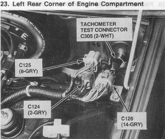
and in case u dont have the connector like me...its the one under the O2 signal wire(white).... 
<TABLE WIDTH="90%" CELLSPACING=0 CELLPADDING=0 ALIGN=CENTER><TR><TD>Quote, originally posted by EE_Chris »</TD></TR><TR><TD CLASS="quote">Shouldn't matter where it goes but there is a picture in this thread showing the 'correct' pin-out for each wire - use it as a reference.</TD></TR></TABLE>
<TABLE WIDTH="90%" CELLSPACING=0 CELLPADDING=0 ALIGN=CENTER><TR><TD>Quote, originally posted by EE_Chris »</TD></TR><TR><TD CLASS="quote">Shouldn't matter where it goes but there is a picture in this thread showing the 'correct' pin-out for each wire - use it as a reference.</TD></TR></TABLE>
03-18-2005, 01:27 PM
#13
Honda-Tech Member
Just to correct something here.. The two black wires are being referred to incorrectly here. One is a ground for the heater, yes.. The second is not a supply voltage to the sensor, its the supply voltage to the heater.
03-22-2005, 03:20 PM
#14
Honda-Tech Member
Join Date: Oct 2002
Location: chicago burbs, Il, USA
Posts: 5,150
Likes: 0
Received 23 Likes
on
23 Posts
<TABLE WIDTH="90%" CELLSPACING=0 CELLPADDING=0 ALIGN=CENTER><TR><TD>Quote, originally posted by Hybrid93Eg »</TD></TR><TR><TD CLASS="quote">Just to correct something here.. The two black wires are being referred to incorrectly here. One is a ground for the heater, yes.. The second is not a supply voltage to the sensor, its the supply voltage to the heater. </TD></TR></TABLE>
NO... one black is heater control from the ECU the other is ignition power.
UNLESS you have a 94-95 teg ECU. then one is ground and the other is heater control from the ECU. AFAIK that is the only exception for Civics and Tegs from 92-00.
NO... one black is heater control from the ECU the other is ignition power.
UNLESS you have a 94-95 teg ECU. then one is ground and the other is heater control from the ECU. AFAIK that is the only exception for Civics and Tegs from 92-00.
03-22-2005, 03:30 PM
#15
Honda-Tech Member
<TABLE WIDTH="90%" CELLSPACING=0 CELLPADDING=0 ALIGN=CENTER><TR><TD>Quote, originally posted by Relic1 »</TD></TR><TR><TD CLASS="quote">
NO... one black is heater control from the ECU the other is ignition power.
UNLESS you have a 94-95 teg ECU. then one is ground and the other is heater control from the ECU. AFAIK that is the only exception for Civics and Tegs from 92-00.</TD></TR></TABLE>
Well, I just pulled up the helm manual for both the 92-95 Civic AND the Helm for the 94+ Integra and sure enough, one is a ground, one is supply for the heater circuit. So just what the hell are you saying again?
Did you ever stop to think that perhaps the heater is "controlled" through the ECU by opening and closing the ground side of the circuit? This is quite often how things are controlled by Honda... Switching the ground side, not the power.
03-22-2005, 06:25 PM
#16
Thread Starter
Join Date: Jan 2004
Location: East Coast, USA
Posts: 524
Likes: 0
Received 0 Likes
on
0 Posts
well here is waht I did....let me knwo whatsup
spliced black and green together and ran into a ground
white to existing o2
black to A6 on ECU
still threw a code 41...duno what i did wrong...but im guessins it has sumthin to do with the black and green that i grounded..??
spliced black and green together and ran into a ground
white to existing o2
black to A6 on ECU
still threw a code 41...duno what i did wrong...but im guessins it has sumthin to do with the black and green that i grounded..??
03-22-2005, 06:40 PM
#17
Junior Member
Join Date: Oct 2004
Location: Atlanta
Posts: 18
Likes: 0
Received 0 Likes
on
0 Posts
the black 12v is not a ground, you run that to c125, or do what i did and just splice it into B1
the reason why it is not working is because your heat controller on your o2 sensor is not getting any voltage
i used this write up to wire my o2 up today
the reason why it is not working is because your heat controller on your o2 sensor is not getting any voltage
i used this write up to wire my o2 up today
03-22-2005, 07:02 PM
#18
Honda-Tech Member
<TABLE WIDTH="90%" CELLSPACING=0 CELLPADDING=0 ALIGN=CENTER><TR><TD>Quote, originally posted by d0nny »</TD></TR><TR><TD CLASS="quote">the black 12v is not a ground, you run that to c125, or do what i did and just splice it into B1
the reason why it is not working is because your heat controller on your o2 sensor is not getting any voltage
i used this write up to wire my o2 up today</TD></TR></TABLE>
A6 is the heater control output on the ECU. Now the question here is as follows. Is this a ground toggled connection or power? If its a ground toggled connection, then you are right, its not getting any power.
It looks like that is the case. A6 is listed as the ground of the connection at the ECU. So the ECU controls the voltage by switching the ground.
So, to recap, I wasn't wrong. One of the blacks is indeed a ground and runs into the ECU. We clear now?
03-23-2005, 02:55 AM
#19
Honda-Tech Member
<TABLE WIDTH="90%" CELLSPACING=0 CELLPADDING=0 ALIGN=CENTER><TR><TD>Quote, originally posted by JD95hatch »</TD></TR><TR><TD CLASS="quote">well here is waht I did....let me knwo whatsup
spliced black and green together and ran into a ground
white to existing o2
black to A6 on ECU
still threw a code 41...duno what i did wrong...but im guessins it has sumthin to do with the black and green that i grounded..??</TD></TR></TABLE>
<TABLE WIDTH="90%" CELLSPACING=0 CELLPADDING=0 ALIGN=CENTER><TR><TD>Quote, originally posted by Relic1 »</TD></TR><TR><TD CLASS="quote">black - Heater control - A6 ECU - only wire to run through firewall.
green - O2 ground - splice into one of the black wires that runs to the thermostat housing.
white - O2 signal - use existing sheilded O2 wire to D14
black - heater power - power from C125 (large group of yel/blk wires)
</TD></TR></TABLE>
You ask a question, you get correct directions, you disregard them and still wonder why you have a code??
Wow...
And now that you went ahead and straight up grounded the heater control wire, you've probably burned the heater element out. The ECU controls the ground side of this circuit - it does not keep it grounded, it is a pulsed waveform. This means that there are periods of time when there is no current flowing through it and thus no heat is being produced. Just straight grounding it never gives it that cool down period.
If I were you, I'd grab a meter and make sure the heater element is still in spec (15-40ohms). I'd then follow the directions that were given as they are correct.
As far as what the ECU does - it does indeed control the ground side of the circuit.
The only time that Honda went with the reverse, that I can recall off-hand, is the IAB circuit on the GS-R. For most all years, power is applied and the ECU controls the ground but there is a year or two that the ECU supplies a switched +12v (I wanna say its in the 98-00 Tegs - one of those model years).
spliced black and green together and ran into a ground
white to existing o2
black to A6 on ECU
still threw a code 41...duno what i did wrong...but im guessins it has sumthin to do with the black and green that i grounded..??</TD></TR></TABLE>
<TABLE WIDTH="90%" CELLSPACING=0 CELLPADDING=0 ALIGN=CENTER><TR><TD>Quote, originally posted by Relic1 »</TD></TR><TR><TD CLASS="quote">black - Heater control - A6 ECU - only wire to run through firewall.
green - O2 ground - splice into one of the black wires that runs to the thermostat housing.
white - O2 signal - use existing sheilded O2 wire to D14
black - heater power - power from C125 (large group of yel/blk wires)
</TD></TR></TABLE>You ask a question, you get correct directions, you disregard them and still wonder why you have a code??
Wow...
And now that you went ahead and straight up grounded the heater control wire, you've probably burned the heater element out. The ECU controls the ground side of this circuit - it does not keep it grounded, it is a pulsed waveform. This means that there are periods of time when there is no current flowing through it and thus no heat is being produced. Just straight grounding it never gives it that cool down period.
If I were you, I'd grab a meter and make sure the heater element is still in spec (15-40ohms). I'd then follow the directions that were given as they are correct.
As far as what the ECU does - it does indeed control the ground side of the circuit.
The only time that Honda went with the reverse, that I can recall off-hand, is the IAB circuit on the GS-R. For most all years, power is applied and the ECU controls the ground but there is a year or two that the ECU supplies a switched +12v (I wanna say its in the 98-00 Tegs - one of those model years).
03-23-2005, 12:23 PM
#20
Thread Starter
Join Date: Jan 2004
Location: East Coast, USA
Posts: 524
Likes: 0
Received 0 Likes
on
0 Posts
i was getting mixed opinions and then i was pointed out to a writeup online and thats where i went..it was easier this way....but apparently the wrong way.
but your wrong..i didnt ground teh heater control wire...if u read what i did...i spliced it into A6...whcih is EXACTLY what you told me to do...
but your wrong..i didnt ground teh heater control wire...if u read what i did...i spliced it into A6...whcih is EXACTLY what you told me to do...
03-23-2005, 12:54 PM
#21
Honda-Tech Member
<TABLE WIDTH="90%" CELLSPACING=0 CELLPADDING=0 ALIGN=CENTER><TR><TD>Quote, originally posted by JD95hatch »</TD></TR><TR><TD CLASS="quote">i was getting mixed opinions and then i was pointed out to a writeup online and thats where i went..it was easier this way....but apparently the wrong way.
but your wrong..i didnt ground teh heater control wire...if u read what i did...i spliced it into A6...whcih is EXACTLY what you told me to do...</TD></TR></TABLE>
This has been covered in a few posts back. A6 IS A GROUND. You get it?
but your wrong..i didnt ground teh heater control wire...if u read what i did...i spliced it into A6...whcih is EXACTLY what you told me to do...</TD></TR></TABLE>
This has been covered in a few posts back. A6 IS A GROUND. You get it?
03-24-2005, 03:31 AM
#23
Honda-Tech Member
*shakes head*
The heater control is a SWITCHED ground - not a permanent ground like the negative terminal on the battery.
Why is this so hard to follow:
black - Heater control - A6 ECU - only wire to run through firewall.
green - O2 ground - splice into one of the black wires that runs to the thermostat housing.
white - O2 signal - use existing sheilded O2 wire to D14
black - heater power - power from C125 (large group of yel/blk wires)
NEITHER of those 2 black wires should be spliced/connected to or any combo you seem to be able to come up with. Run one of them to C125 so it has +12v and run the other black wire back to A6.
03-24-2005, 09:28 AM
#24
Thread Starter
Join Date: Jan 2004
Location: East Coast, USA
Posts: 524
Likes: 0
Received 0 Likes
on
0 Posts
i understand its a GROUND...whether switched or not...wtf...and how many times do i have to meniton i ran it to A6?
obvioulsy one black is connected to A6...i dont know what more to tell you...thast exactly what i ******* did.
<TABLE WIDTH="90%" CELLSPACING=0 CELLPADDING=0 ALIGN=CENTER><TR><TD>Quote, originally posted by Hybrid93Eg »</TD></TR><TR><TD CLASS="quote">A6 IS A GROUND. You get it?</TD></TR></TABLE>...do you get it?
did i mention i ran the black wire into A6??
03-24-2005, 09:42 AM
#25
Honda-Tech Member
Join Date: Oct 2002
Location: chicago burbs, Il, USA
Posts: 5,150
Likes: 0
Received 23 Likes
on
23 Posts
I will say this one more time....
one side of the heater goes to A6.
it's a switched PWM ground signal not a solid value, that's why I don't call it ground. It really doesn't matter.
the other side of the heater needs to be connected to ignition power. Do not connect it to ground or you will get the CEL. It needs power spliced from one of the yel/blk wires in C125.
Follow that and you will not get the CEL, unless your O2 is bad.
BTW, grounding the other side of the heater will not blow the O2's heater, it simply will not do anything.
I would explain why but I don't have the energy to explain how the circuitry in the ECU works right now.