
My Build - Nothing Fancy but... It is mine. (Optimized Pics - Still Pic Heavy)
 07-10-2015, 11:41 PM
#1
Hysterically Calm
Thread Starter
I finally got myself an engine stand so I've started working on my build.
I don't have a budget per say being I don't really have a time line. When I have some cash, I'll throw it at it. Wherever it stops is my budget.
I'm starting with the engine and since this is my first tear down and rebuild/build I'm sticking to the cheap D15B7 that I pulled out of the car.
So lets get started. The head has been pulled off the block for about a year and is now back on the block that is in the car. So what I have is the original block from the car since I bought it used. So yes, it might not be original to the car but it probably is. The serial starts with a 4 so was done in 94 for an early 95 would be my guess since the new year cars always come out of the end of the previous year.
I did a little cleanup on the outside first at a spray and wash stall when no one was looking, then with a steal wire brush and Dawn dishwater. Don't worry I immediately oiled the cylinders and ran the pistons a little after the spray and wash stall.
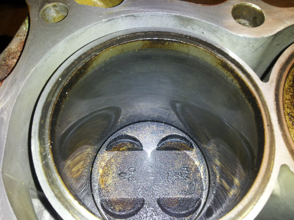
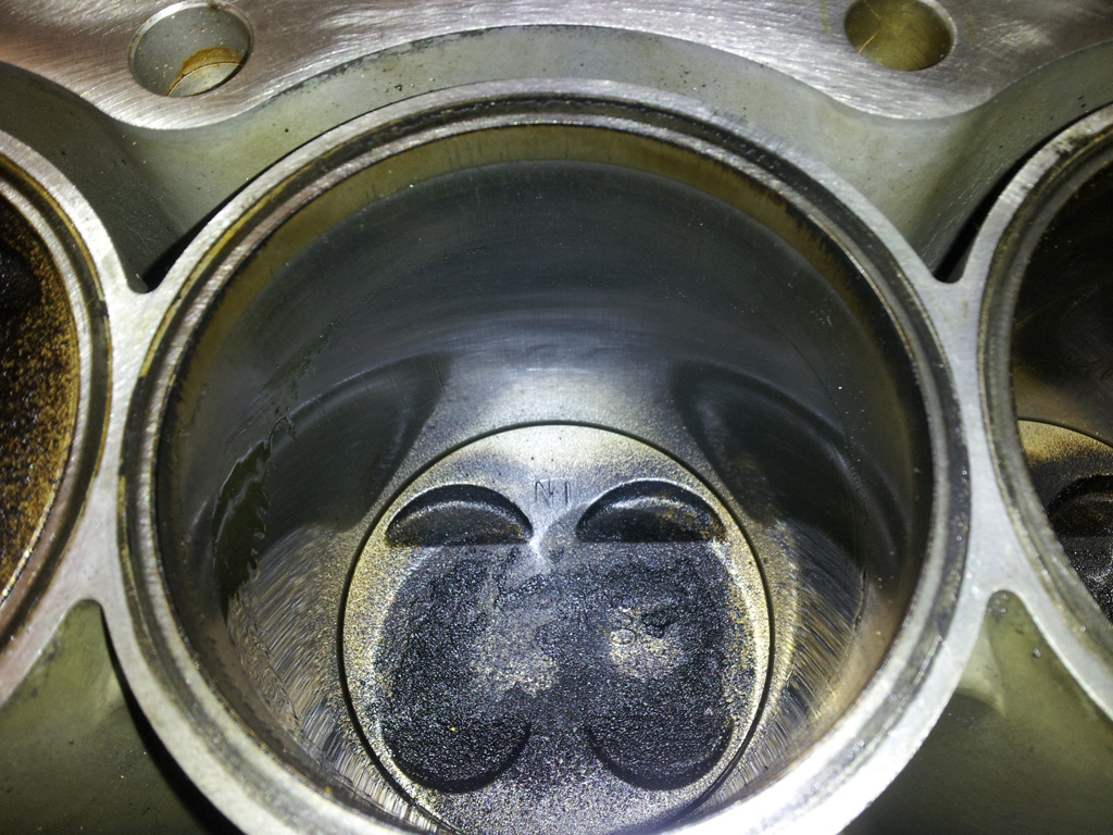
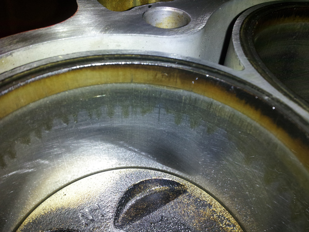
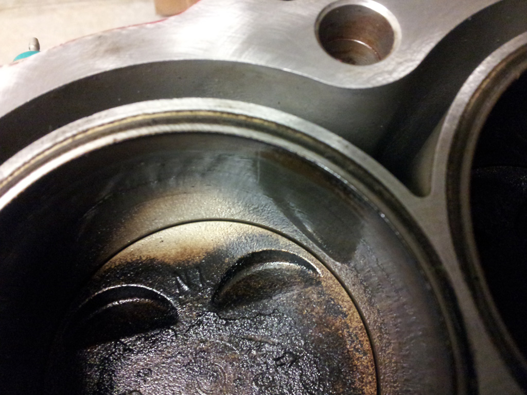
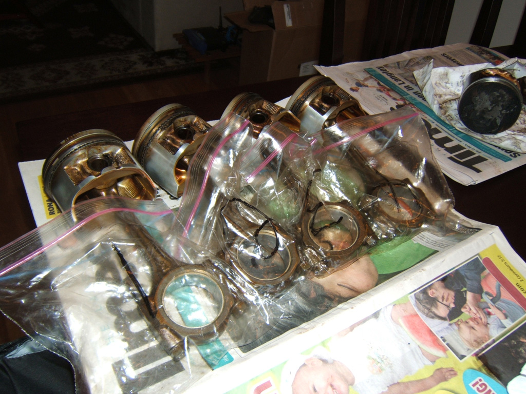
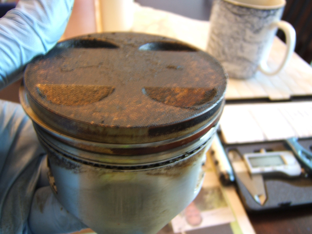
Anyways, here is the pics of the piston tops and then the cylinders. #2 cylinder I had a mess up when I was using a piece of wire hanger to find TDC. On the number two I wasn't paying attention and the hanger slid to the edge. I think I ever so slightly scratch the cylinder wall but nothing I can feel with my finger nail. I think it's getting a bore and hone anyway so that will vanish. You can see it in the pics.
Piston Tops #4, #3, #2, #1
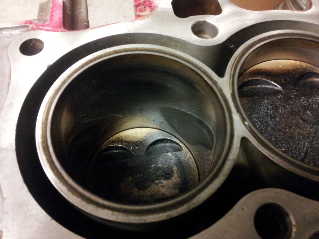
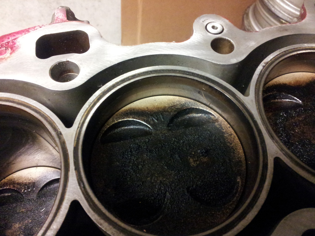
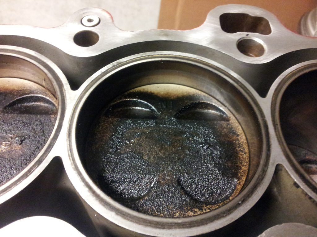
Cylinder Walls #4, #3, #2, #1
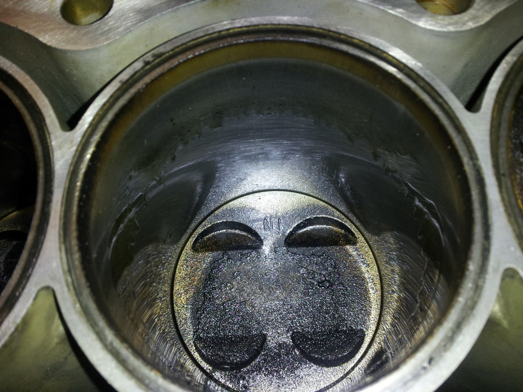
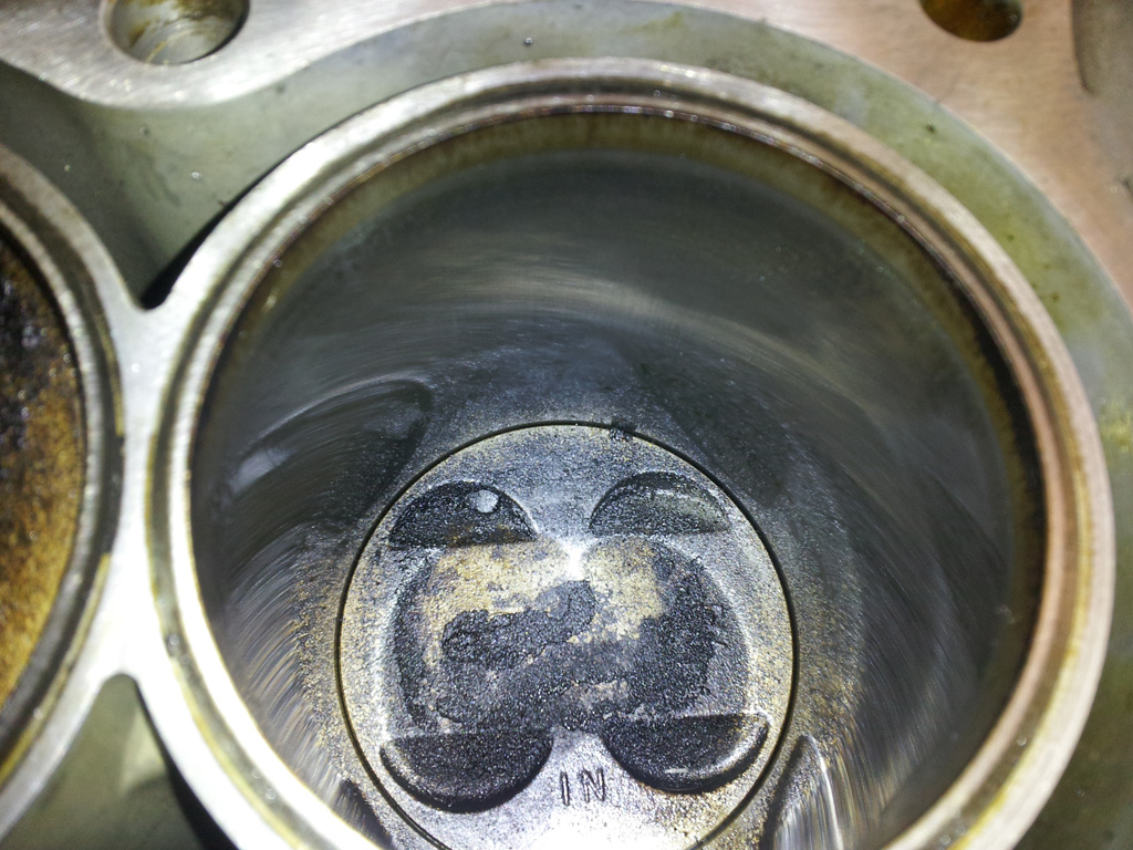
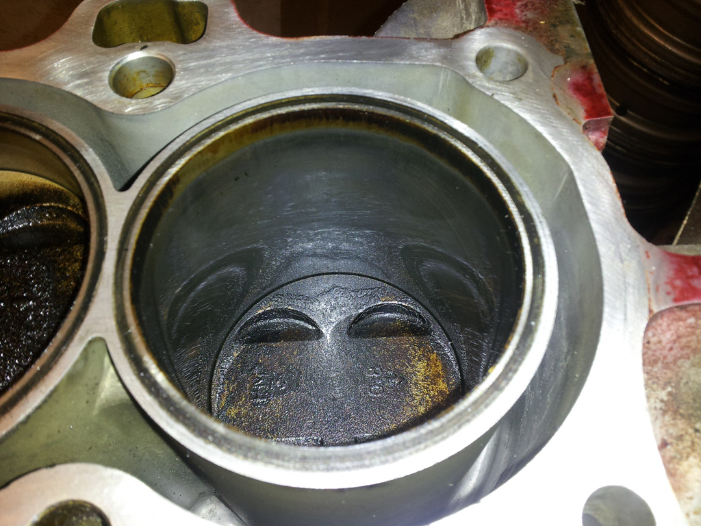
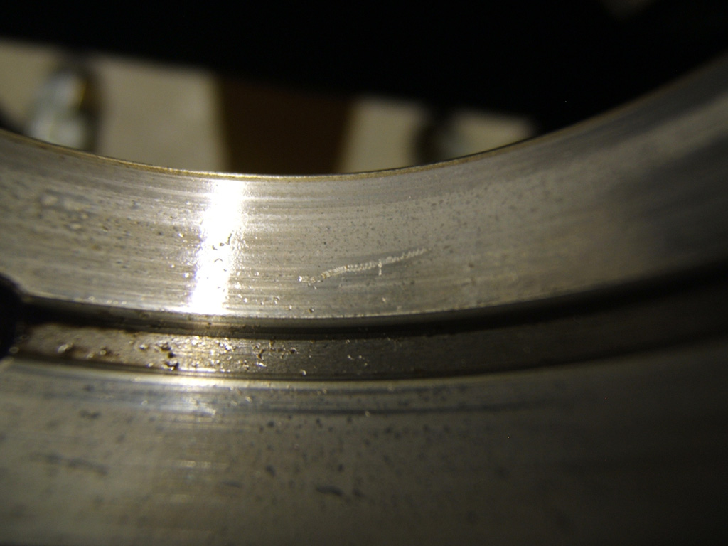
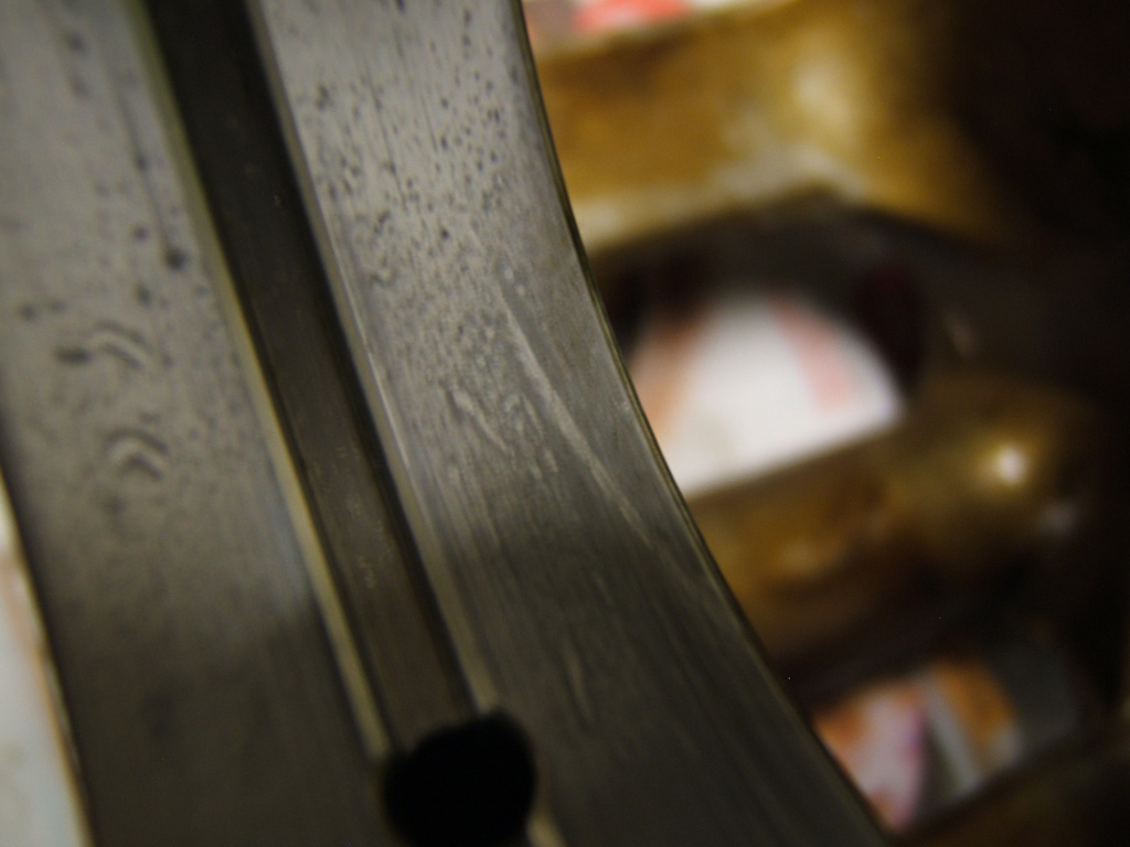
The next two show the scratch of #2. The first pic is how the scratch looks normally, the second pic shows the oil highlighting it as it drools down. As I said though, can't feel it with my finger nail, at least not through the glove. So maybe it's nothing. I did run the motor a little while after that mishap. Needless to say, I use my long and short 3/8" extension now.
I don't have a budget per say being I don't really have a time line. When I have some cash, I'll throw it at it. Wherever it stops is my budget.
I'm starting with the engine and since this is my first tear down and rebuild/build I'm sticking to the cheap D15B7 that I pulled out of the car.
So lets get started. The head has been pulled off the block for about a year and is now back on the block that is in the car. So what I have is the original block from the car since I bought it used. So yes, it might not be original to the car but it probably is. The serial starts with a 4 so was done in 94 for an early 95 would be my guess since the new year cars always come out of the end of the previous year.
I did a little cleanup on the outside first at a spray and wash stall when no one was looking, then with a steal wire brush and Dawn dishwater. Don't worry I immediately oiled the cylinders and ran the pistons a little after the spray and wash stall.
Anyways, here is the pics of the piston tops and then the cylinders. #2 cylinder I had a mess up when I was using a piece of wire hanger to find TDC. On the number two I wasn't paying attention and the hanger slid to the edge. I think I ever so slightly scratch the cylinder wall but nothing I can feel with my finger nail. I think it's getting a bore and hone anyway so that will vanish. You can see it in the pics.
Piston Tops #4, #3, #2, #1
Cylinder Walls #4, #3, #2, #1
The next two show the scratch of #2. The first pic is how the scratch looks normally, the second pic shows the oil highlighting it as it drools down. As I said though, can't feel it with my finger nail, at least not through the glove. So maybe it's nothing. I did run the motor a little while after that mishap. Needless to say, I use my long and short 3/8" extension now.
Last edited by TomCat39; 07-21-2015 at 06:24 PM. Reason: Optimizing Photo's
 07-10-2015, 11:54 PM
#2
Hysterically Calm
Thread Starter
So I flipped the motor over and First I used my feeler gauges to check the rod end play as per the FSM. The largest feeler I could partially get in between the crank and the rod caps was a 0.011". New is supposed to be 0.006"-0.012" with a service limit of 0.018" so I'm still in the New range there.
Then before digging in and starting dis-assembly of the block I check the crank end play. New is supposed to be 0.004"-0.014" with a service limit of 0.018". With my big *** snap on flat tip screw driver, I would go from 0.000" to Just shy of 0.007"
Then before digging in and starting dis-assembly of the block I check the crank end play. New is supposed to be 0.004"-0.014" with a service limit of 0.018". With my big *** snap on flat tip screw driver, I would go from 0.000" to Just shy of 0.007"
Last edited by TomCat39; 07-21-2015 at 06:27 PM. Reason: Optimizing Photo's
07-11-2015, 12:28 AM
#4
Hysterically Calm
Thread Starter
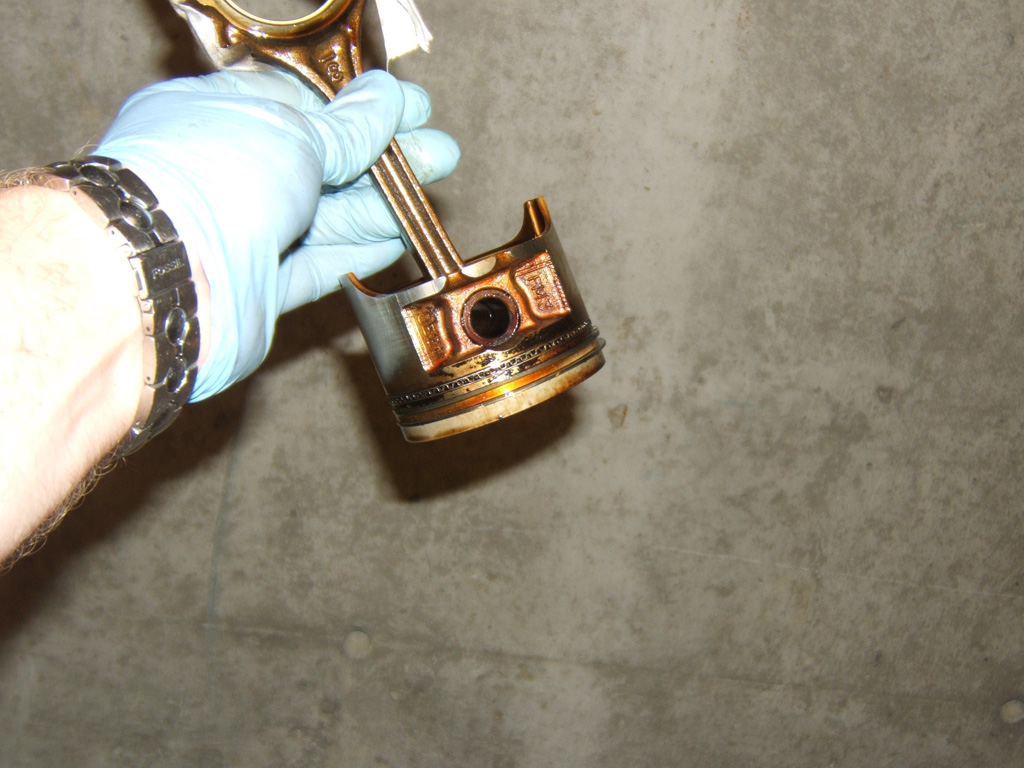
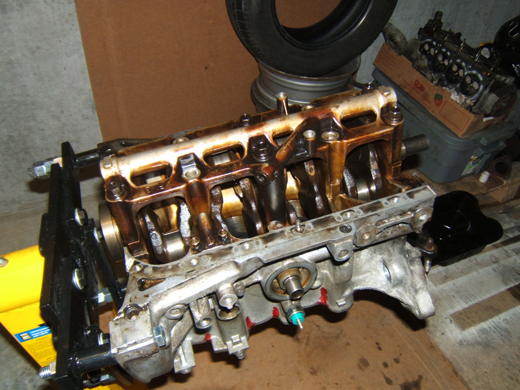
Then after following the loosening sequence for the cap girdle. I pop the girdle off and then begin to take out the pistons. I realized I didn't have any 3/8" hose to put over the bolt studs to keep them from scratching the journals accidently. Then I realized I still had some sport tape so I ripped off pieces and taped over the studs and then the side of the rod. Easily pushed out the pistons making sure to put the cap back onto each one so as to not mix them up.
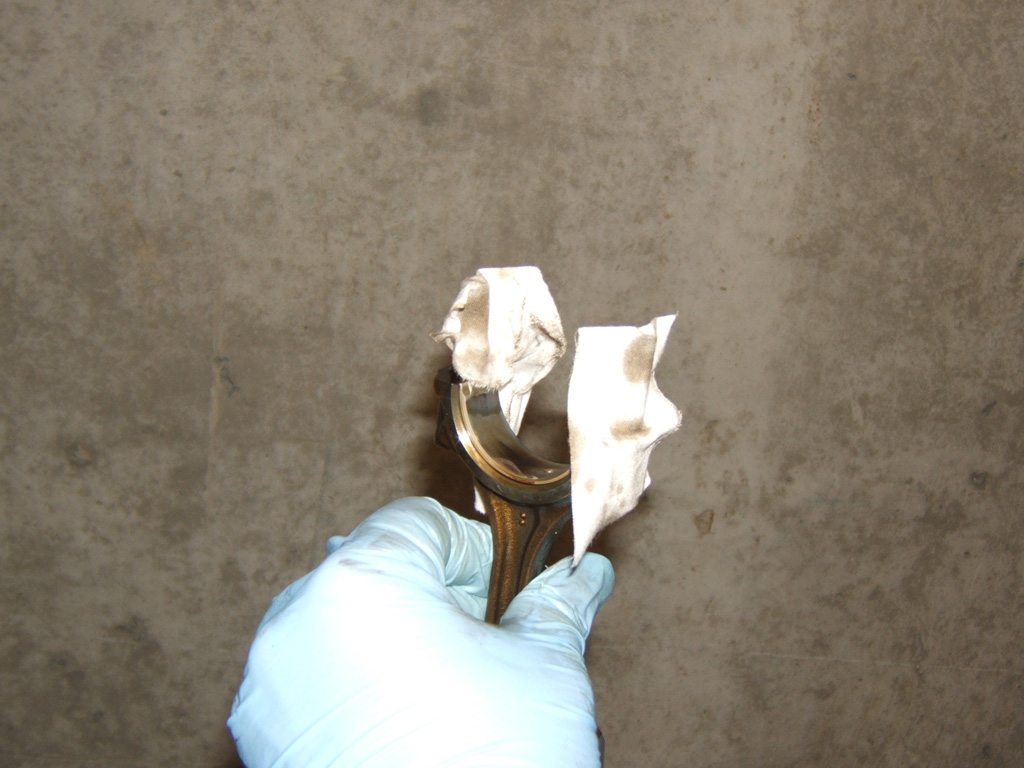
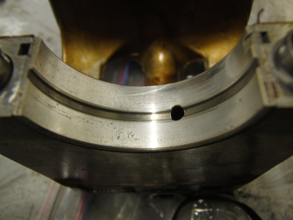
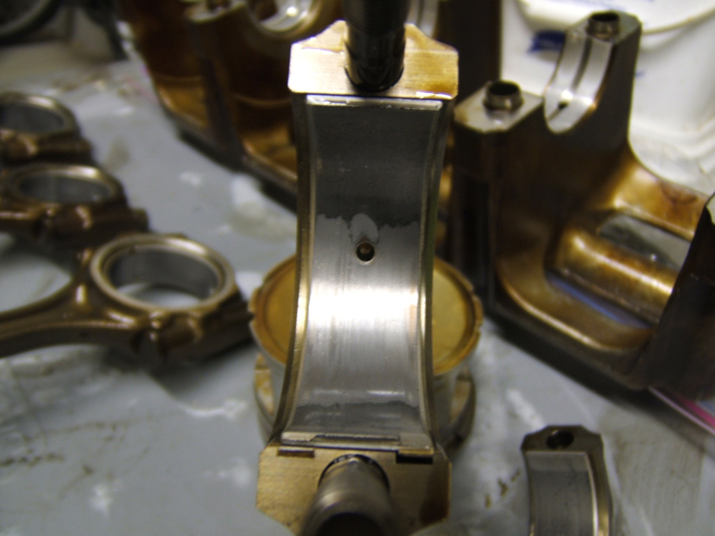
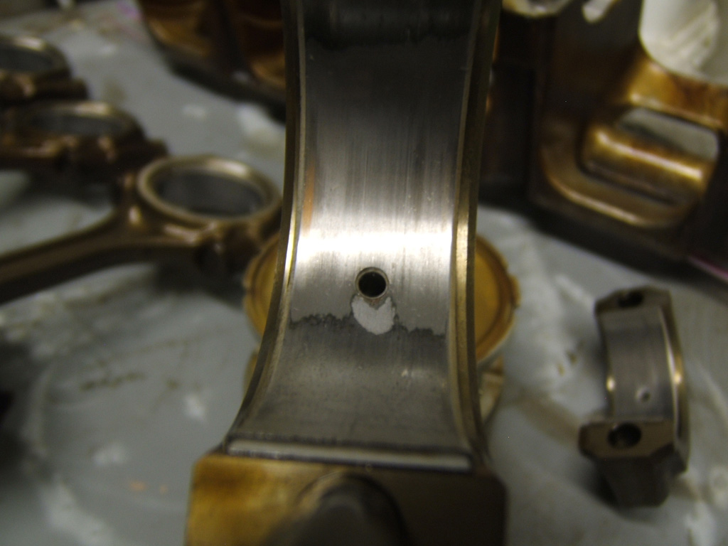
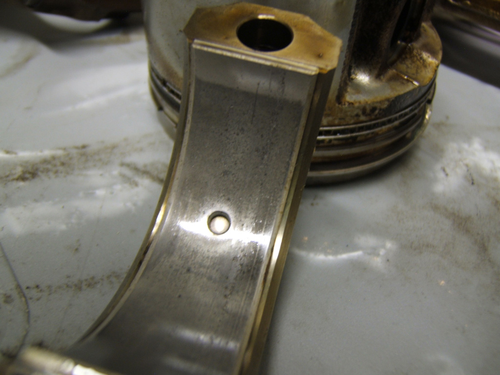
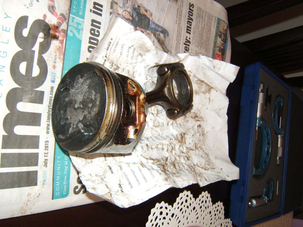
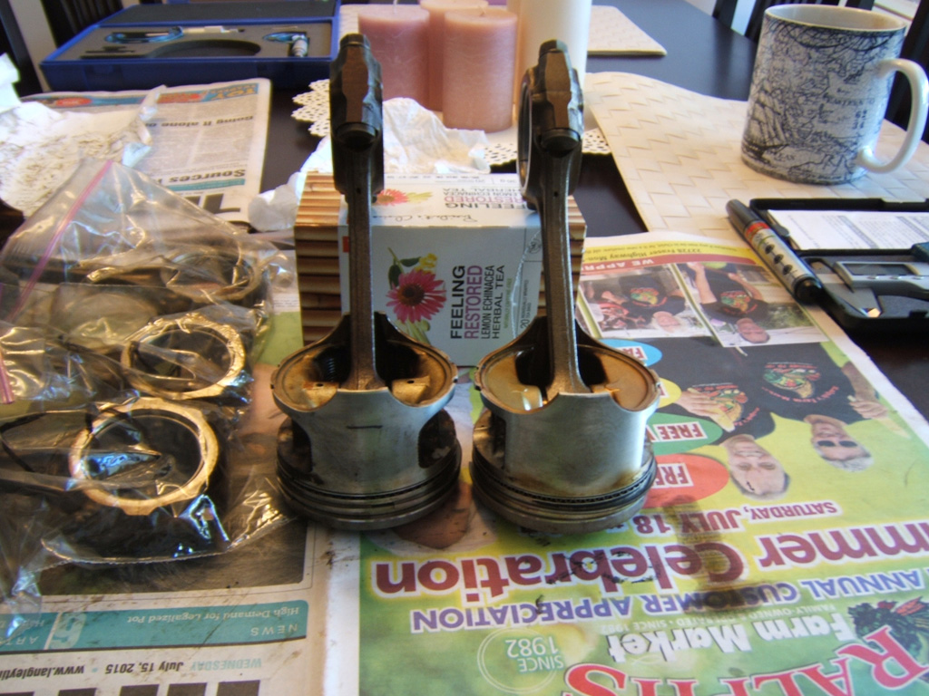
As can be seen here, the B7 rods are indeed super thin and weak. My fingers which or thin compared to many guys are almost thicker than these rods. Hard to believe it goes up to 6800 rpm without snapping.
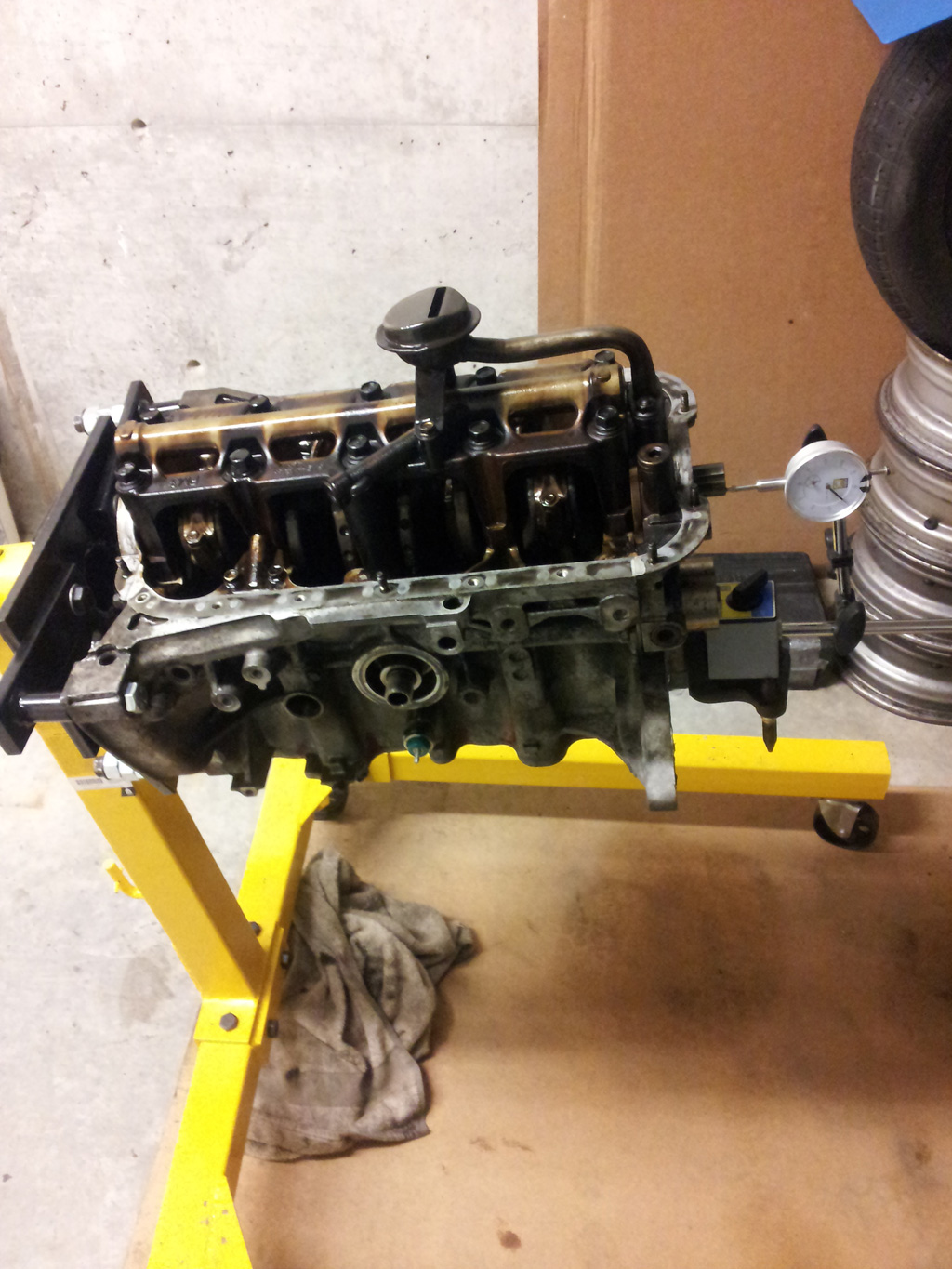
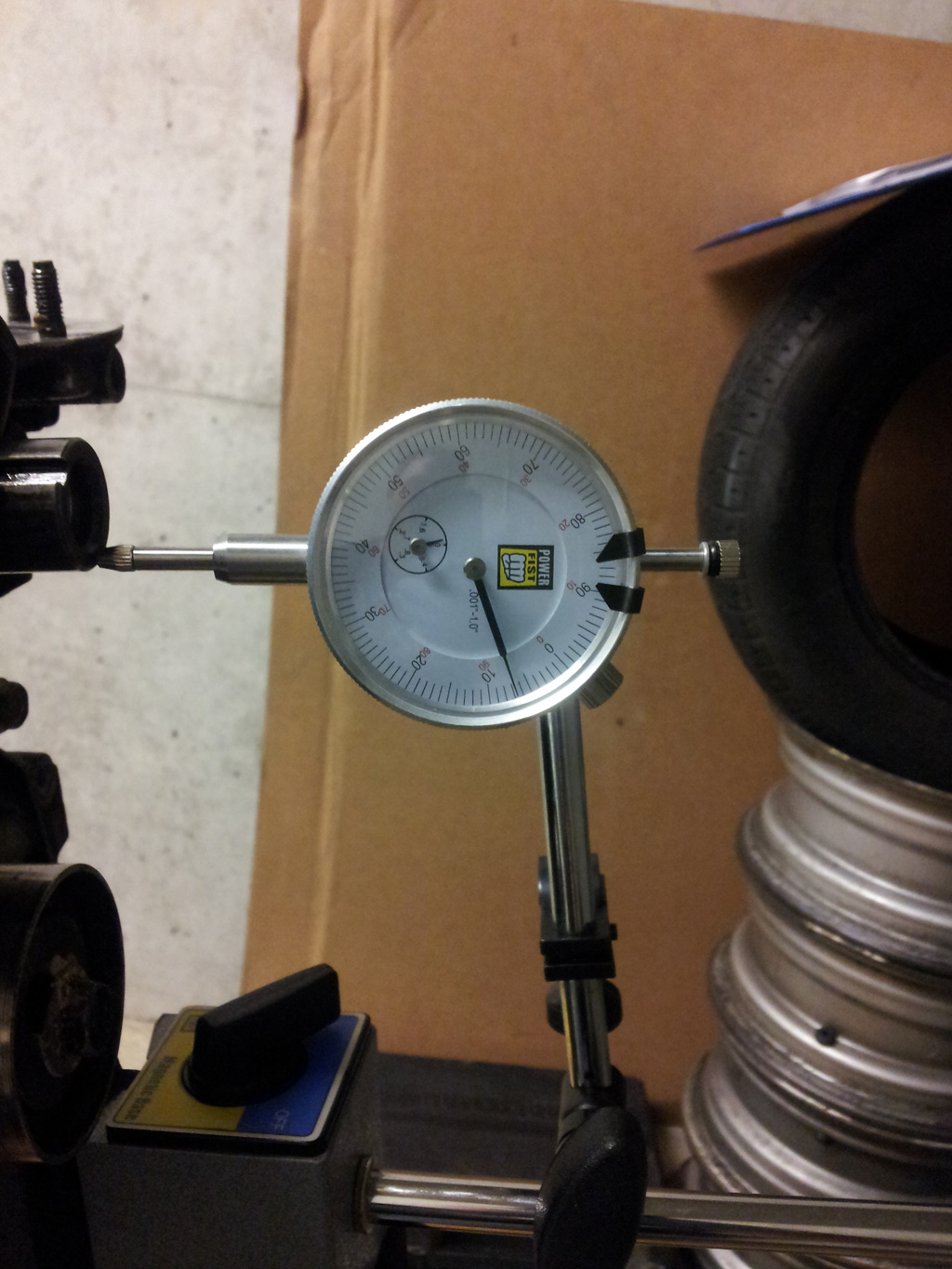
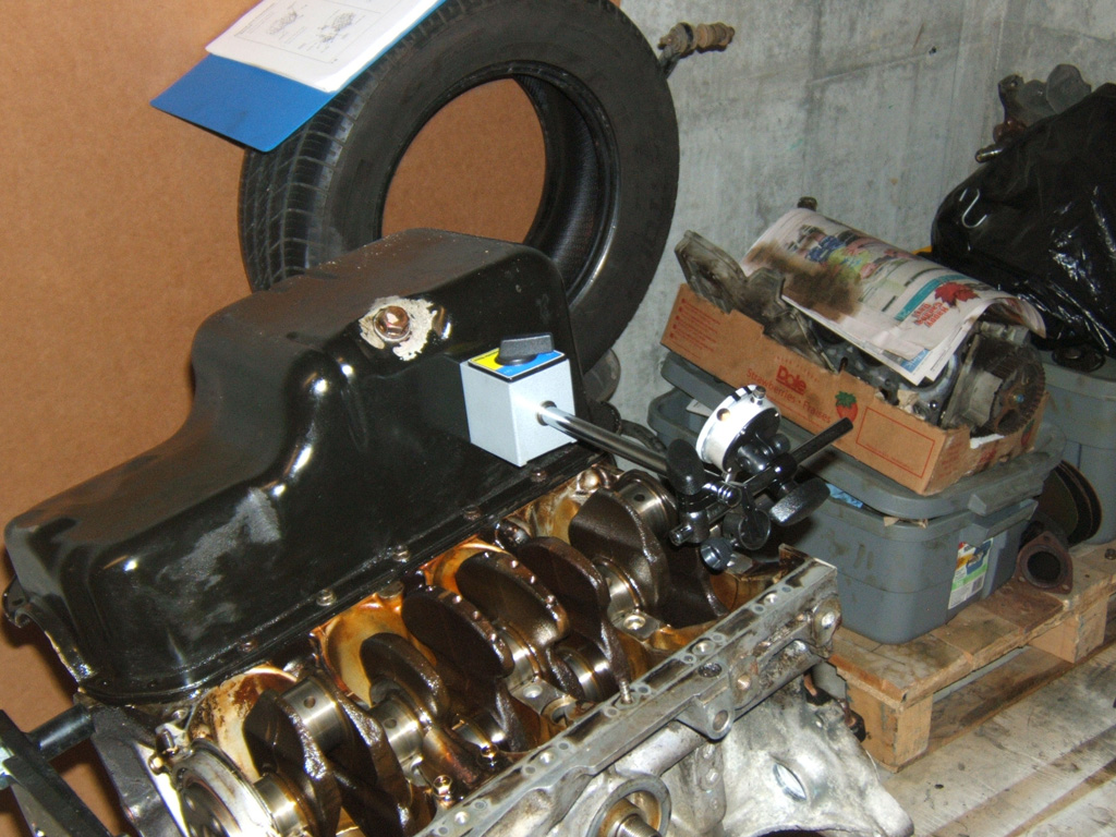
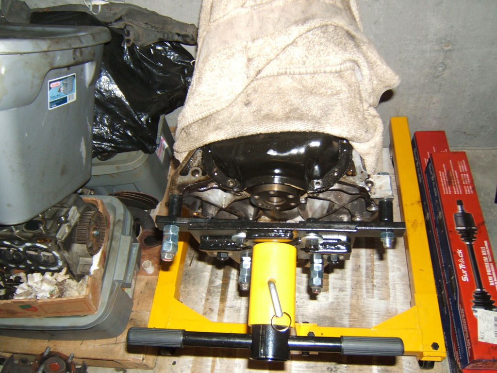
So after I got all the pistons out, I wanted to measure the crank run out. Still lots of oil on the crank so spinning it on the half moon bearings still in the block seemed reasonable. And to have something for my magentic base to attach to, I decided to bolt the steel oil pan to one side and use that to setup on for all the main run out checks.
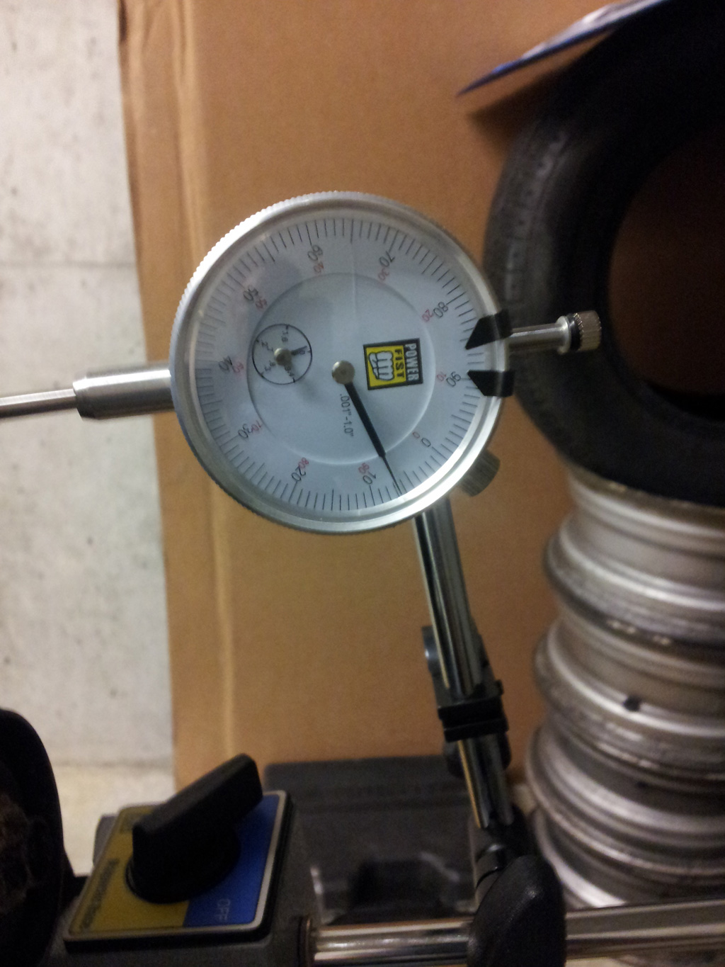
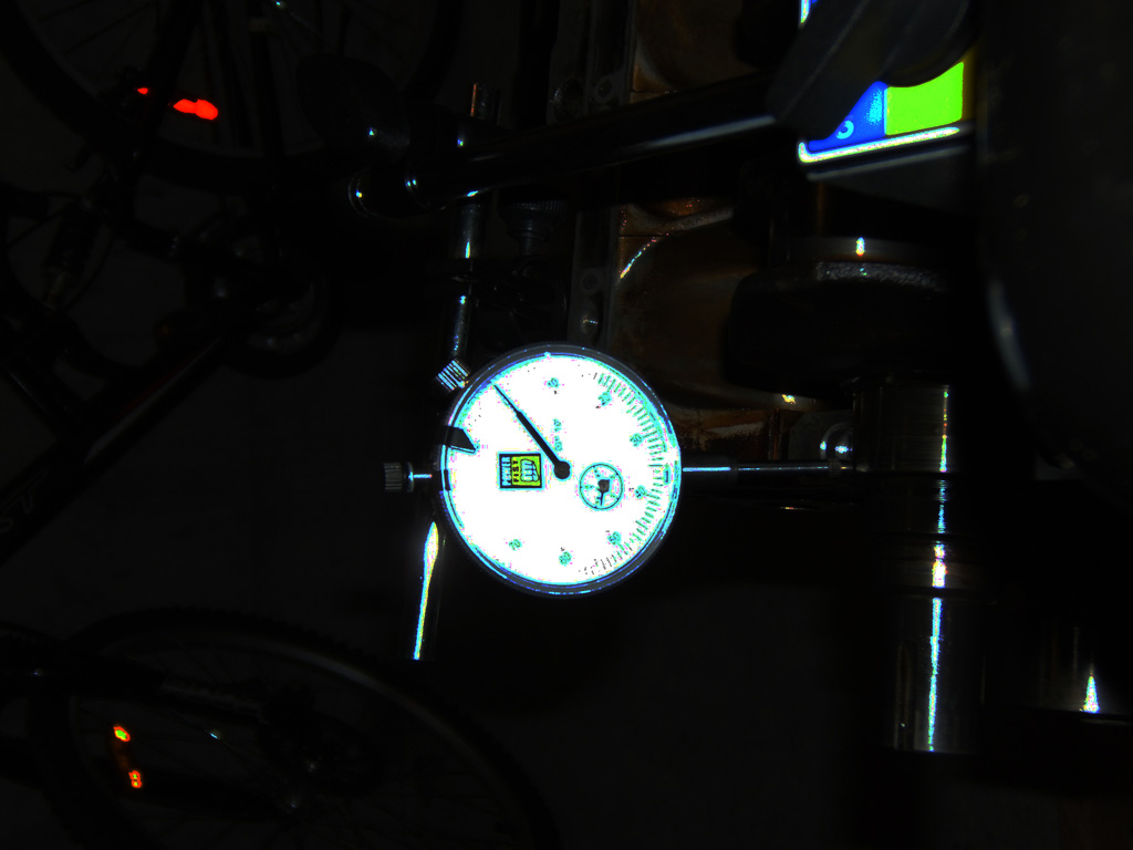
I tried darkening the pic as much as possible so you could see that I zero'd out the dial indicator before spinning the first main.
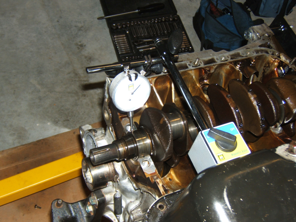
Here is where I setup on the second to last main
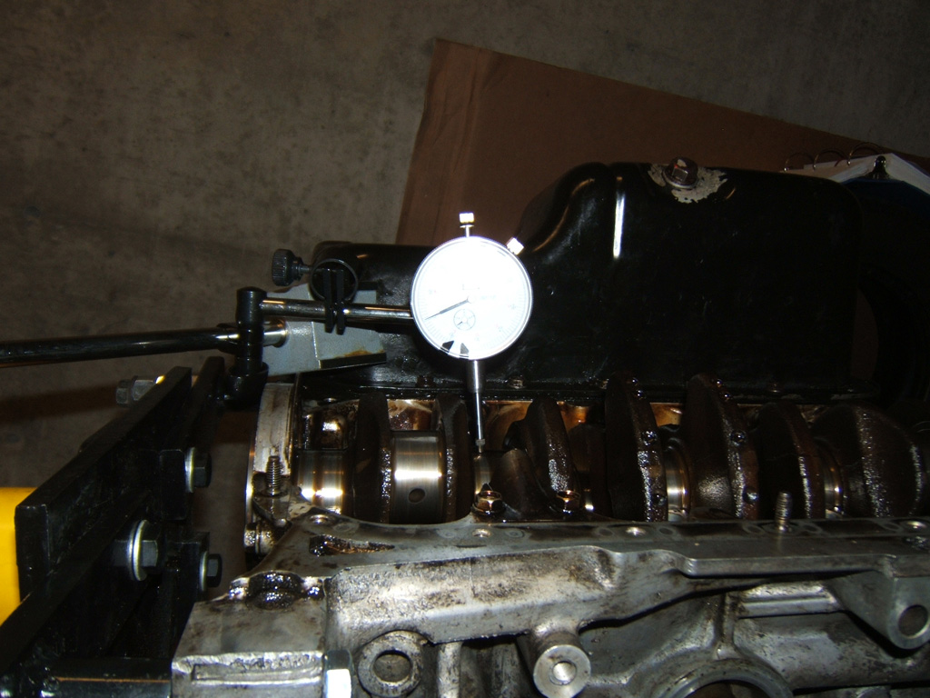
I checked all the mains and the FSM shows total run out when new to be 0.0006" max and a service limit of 0.0012". It also says the difference in run out between the mains may not exceed service limit.
Well, my dial indicator is 0.001" not 0.0001" so... From zero, the lowest run out was between 1/10 and 1/4 of 0.001" so 0.0001"-0.00025".
The highest run out I saw was in the middle mains and it was about 2/3 to 3/4 of 0.001" so 0.00066"-0.00075". So the most variance I had if I take the absolute lowest to the absolute highest approximation is 0.0006" and my run out on all the mains is darn close to new spec.
On the bearings, all the mains looked okay with some wear, one of the rod bearings looked like it was just going to copper which is still softer than the steel and why the journals still seem to be good.
I will get pics of all the bearings another night. This is 3 nights about an hour to two hours and I must say, I'm enjoying myself. Lots more measuring to do before this stuff goes to the jet wash tank.
More to come as the days, weeks, months.... Maybe even years progress.

As can be seen here, the B7 rods are indeed super thin and weak. My fingers which or thin compared to many guys are almost thicker than these rods. Hard to believe it goes up to 6800 rpm without snapping.
So after I got all the pistons out, I wanted to measure the crank run out. Still lots of oil on the crank so spinning it on the half moon bearings still in the block seemed reasonable. And to have something for my magentic base to attach to, I decided to bolt the steel oil pan to one side and use that to setup on for all the main run out checks.
I tried darkening the pic as much as possible so you could see that I zero'd out the dial indicator before spinning the first main.
Here is where I setup on the second to last main
I checked all the mains and the FSM shows total run out when new to be 0.0006" max and a service limit of 0.0012". It also says the difference in run out between the mains may not exceed service limit.
Well, my dial indicator is 0.001" not 0.0001" so... From zero, the lowest run out was between 1/10 and 1/4 of 0.001" so 0.0001"-0.00025".
The highest run out I saw was in the middle mains and it was about 2/3 to 3/4 of 0.001" so 0.00066"-0.00075". So the most variance I had if I take the absolute lowest to the absolute highest approximation is 0.0006" and my run out on all the mains is darn close to new spec.
On the bearings, all the mains looked okay with some wear, one of the rod bearings looked like it was just going to copper which is still softer than the steel and why the journals still seem to be good.
I will get pics of all the bearings another night. This is 3 nights about an hour to two hours and I must say, I'm enjoying myself. Lots more measuring to do before this stuff goes to the jet wash tank.
More to come as the days, weeks, months.... Maybe even years progress.
Last edited by TomCat39; 07-21-2015 at 06:32 PM. Reason: Optimizing Photo's
07-11-2015, 12:35 AM
#5
Hysterically Calm
Thread Starter
Thanks, actually in my third post you can see a head in the back ground photo where I have the oil pan bolted to the block, that's my Y8 head that was pulled from a good working Y8 motor. The owner was doing a swap, probably a b-series and my tech was going to scrap the motor and gave it to me for free. That's what I'm going to be putting onto the B7 block after I do some tweaks.
Trending Topics
 07-11-2015, 07:48 AM
#10
GDD's Resident Derp

Hi TomCat39. Being serious, I wanted to say that it's cool you are doing this with your engine. Of course, I am looking, and reading, and I might pick up a thing or two about how it goes with engines and all in doing so. We all know that some of what I know about cars.. may not be right.
Definite coolness on that engine stand. Great thread.
Sincerely, - Joseph
Definite coolness on that engine stand. Great thread.
Sincerely, - Joseph
07-11-2015, 06:51 PM
#11
Hysterically Calm
Thread Starter
I think I got my proof about Xado Engine Treatment. This block had 2 treatments done with both the original Xado engine treatment tubes and then also 1 treatment with the 120% Xado engine treatment in the syringe.
I was always noticing a bit of knocking when in drive through windows and after awhile, the knocking was actually going away. Then I got stupid and redlined it with the motor bone cold as some little kids really pissed me off one grumpy morning. So I blew some cold running rich exhaust in their faces as they had just went behind my car to sit against the wall after flipping me off for no apparent reason.
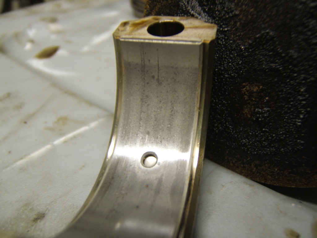
Needless to say, the knocking returned. After tonight, I could see why as I was to copper in all 4 rod big end bearings which you will see soon enough.
But here is the real kewl stuff. I saw examples that Xado provided of their stuff filling in scratches, but we all know marketing will put anything for sales, so since it was from Xado, the skepticism always nagged at the back of the mind.
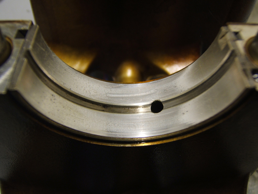
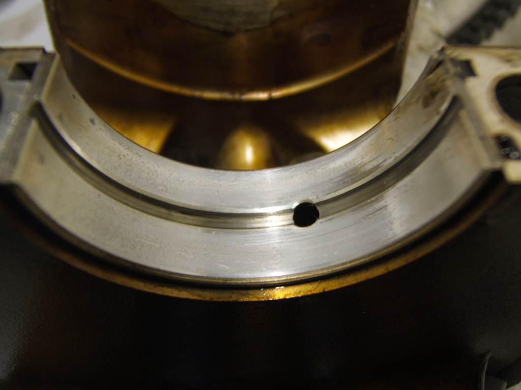
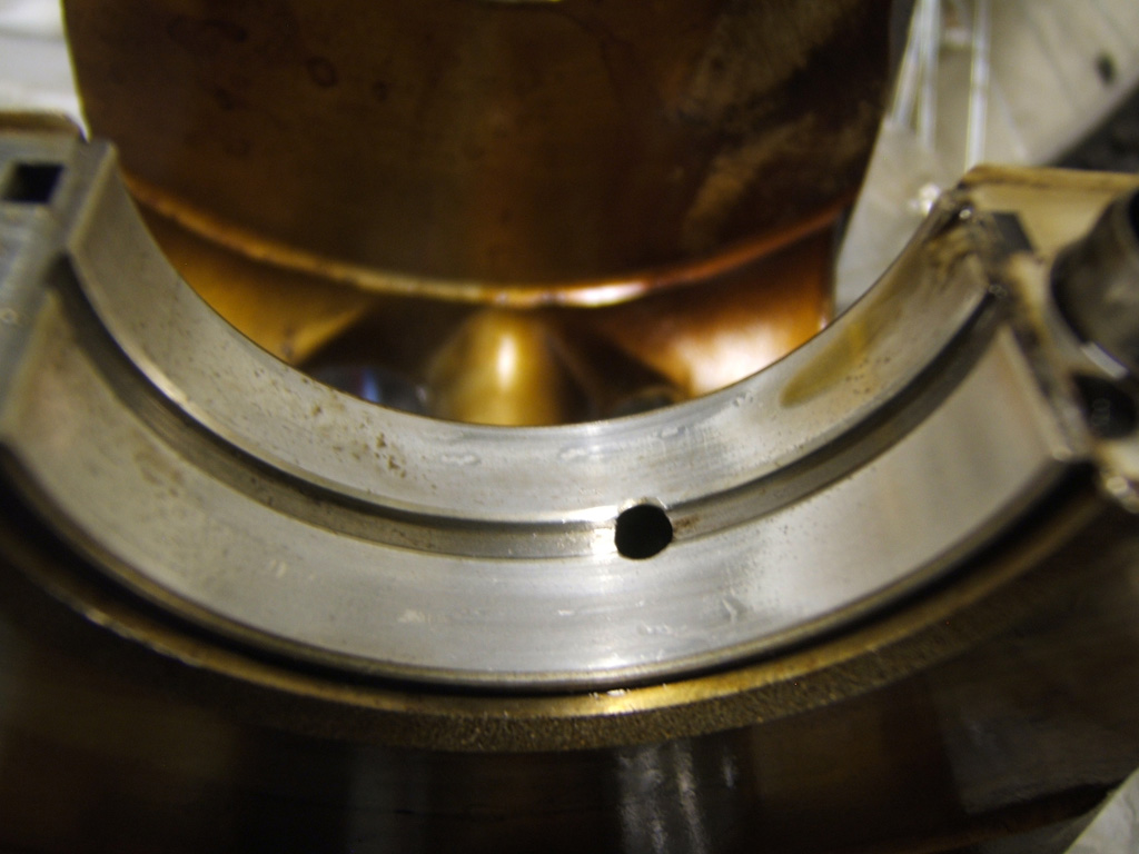
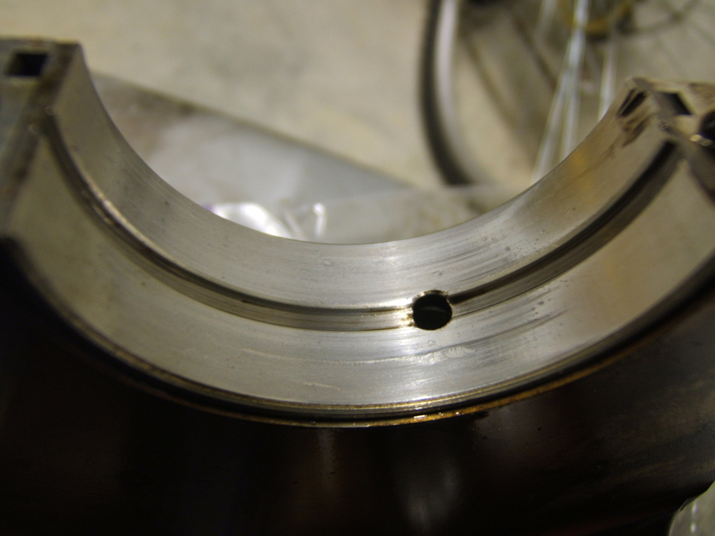
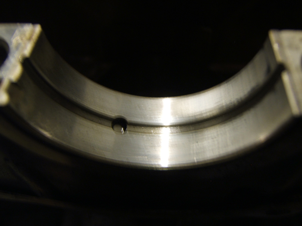
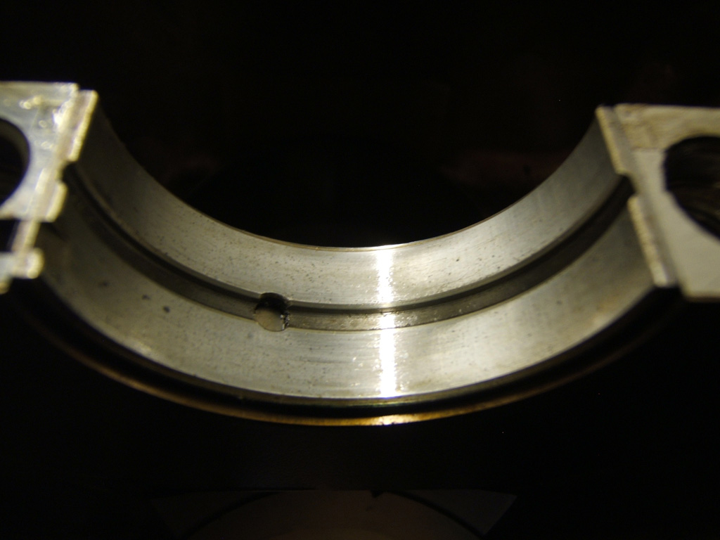
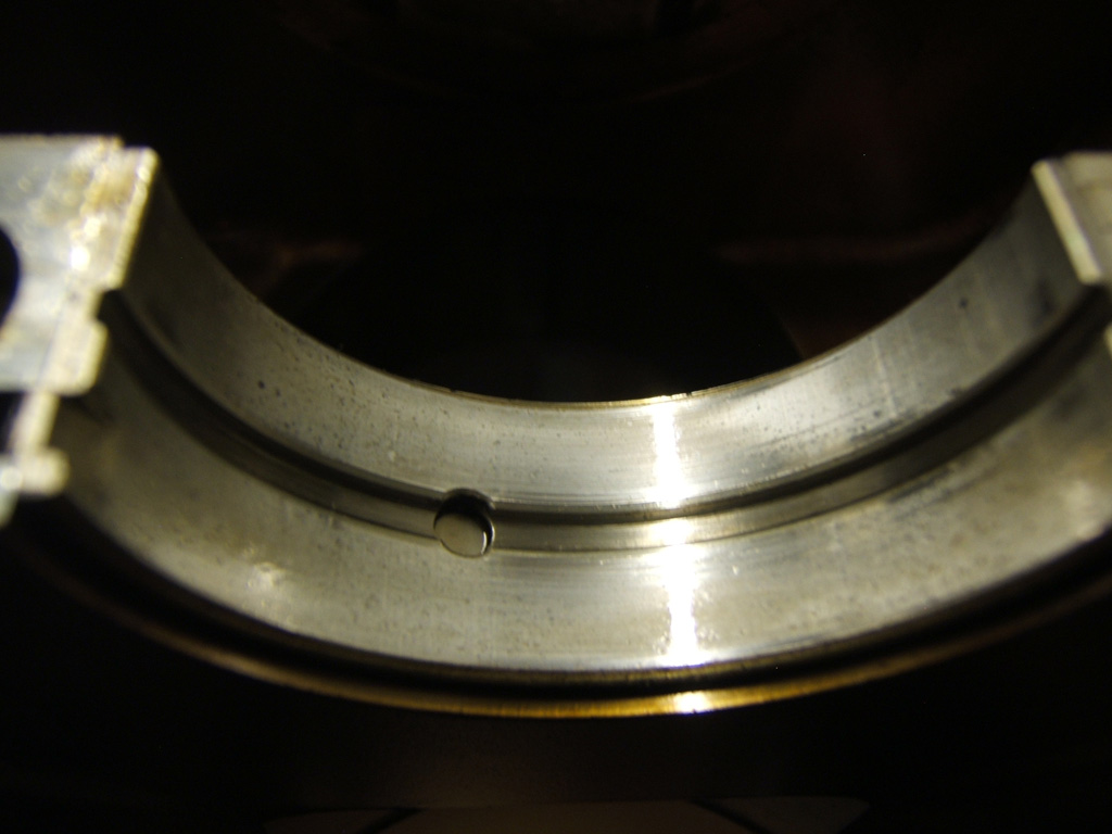
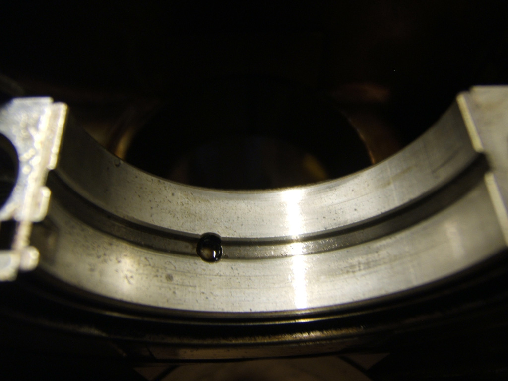
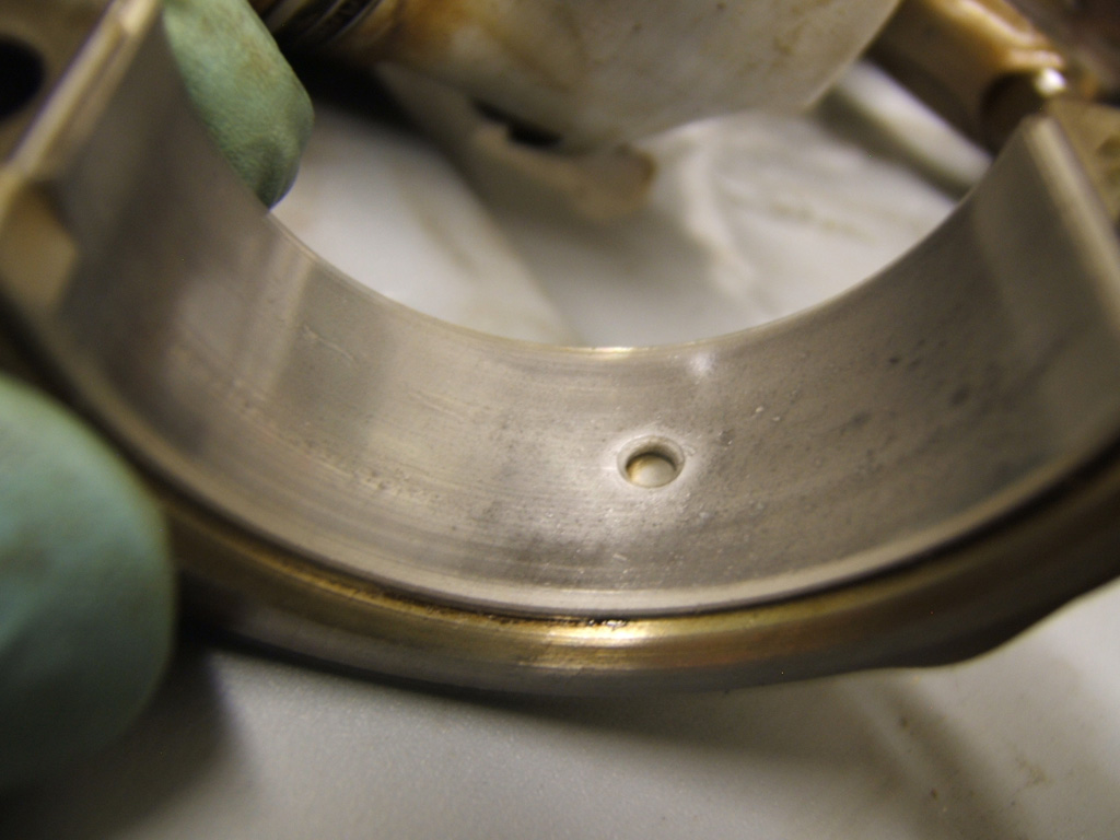
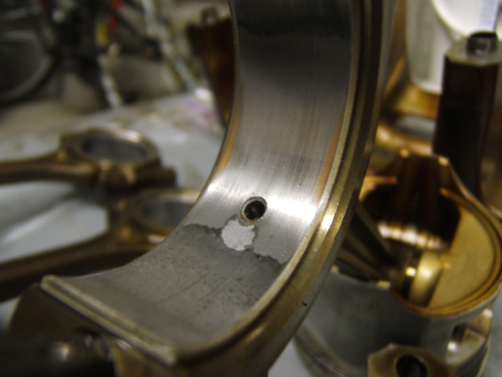
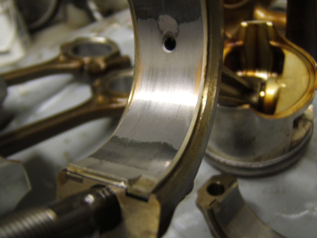
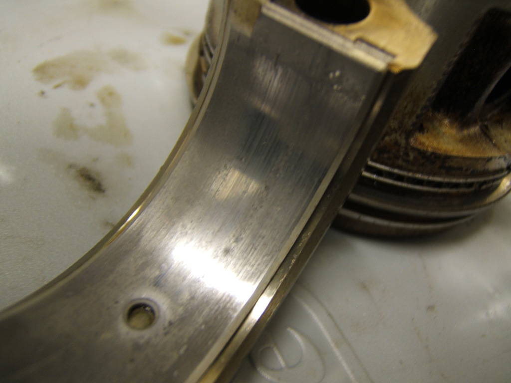
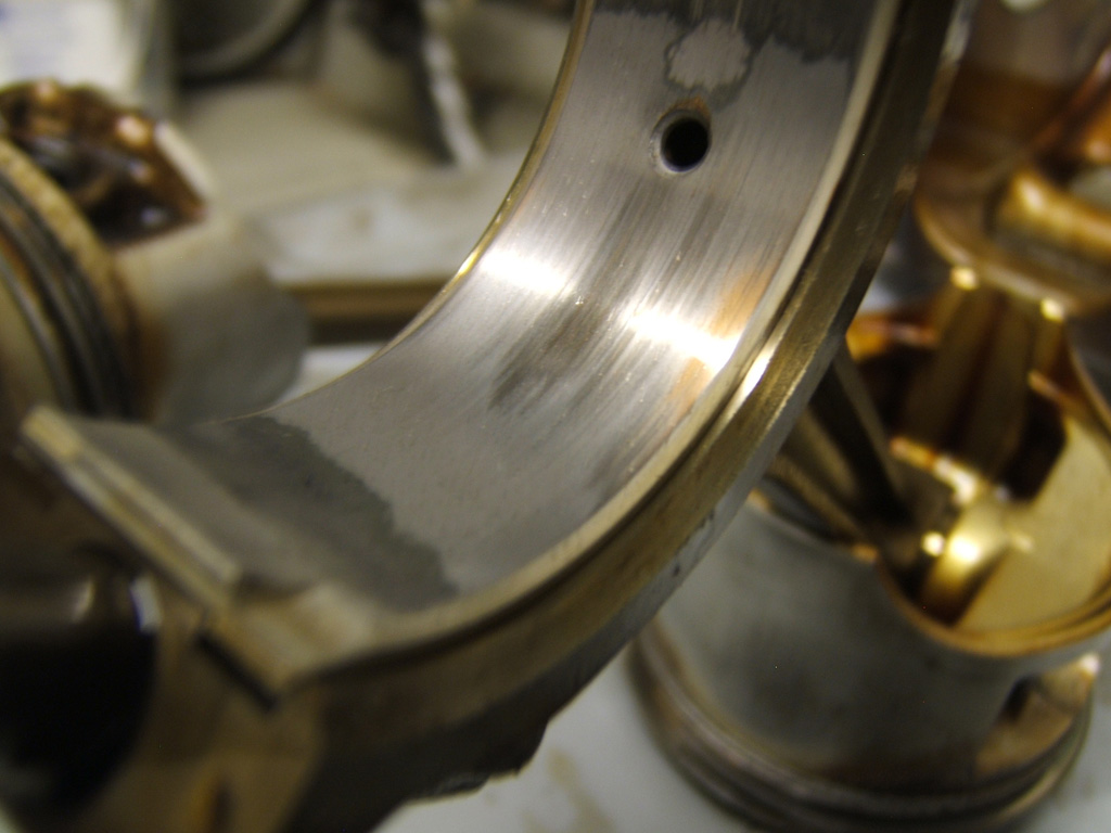
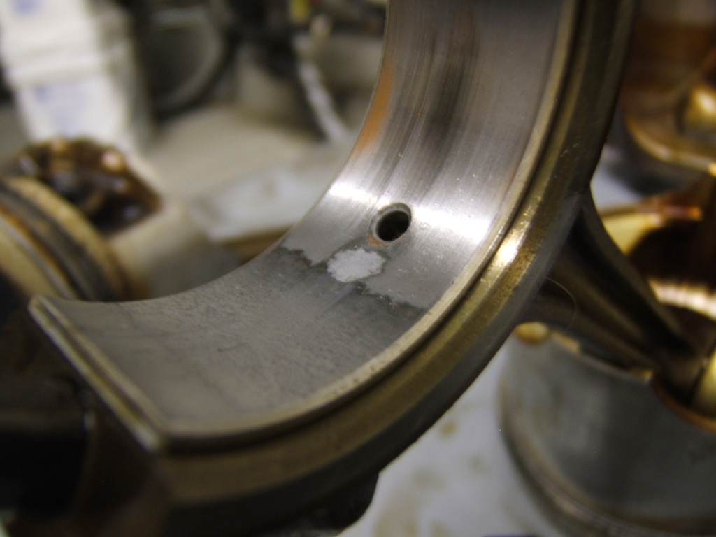
Well check out these main bearing in the cap girdle from this motor... Definite hard core scratches are filled in. You can't feel the difference with your fingernail and you can tell there was some deep ones.
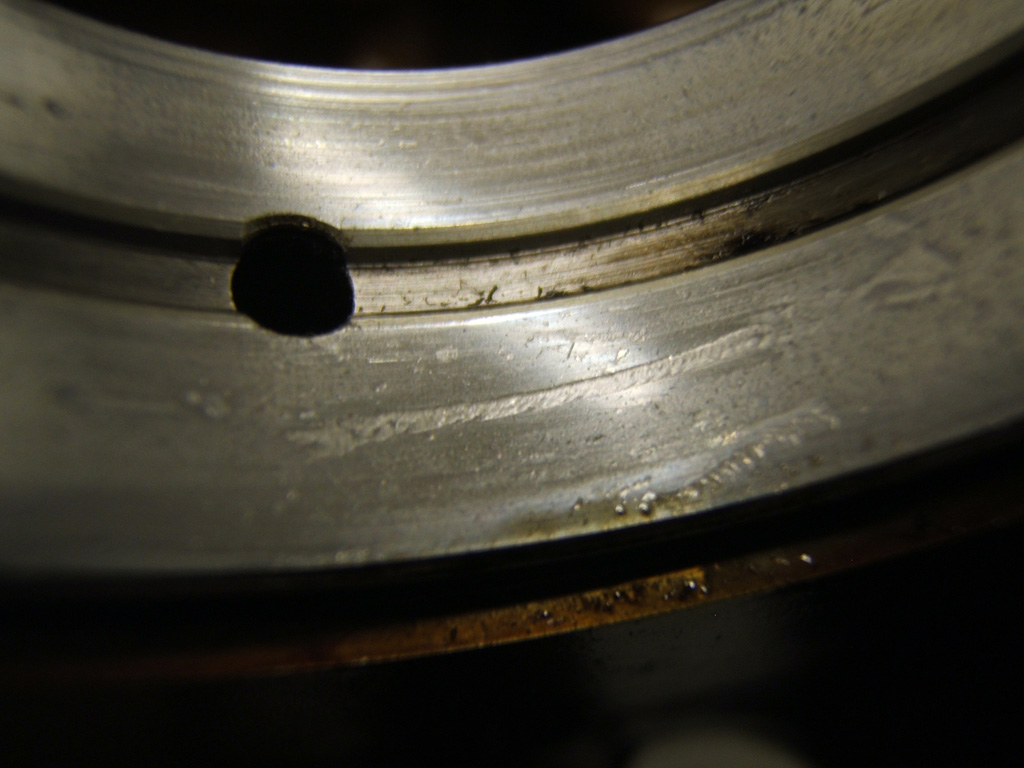
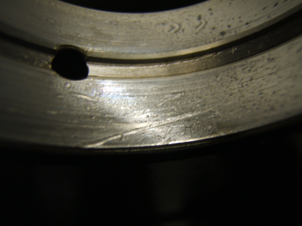
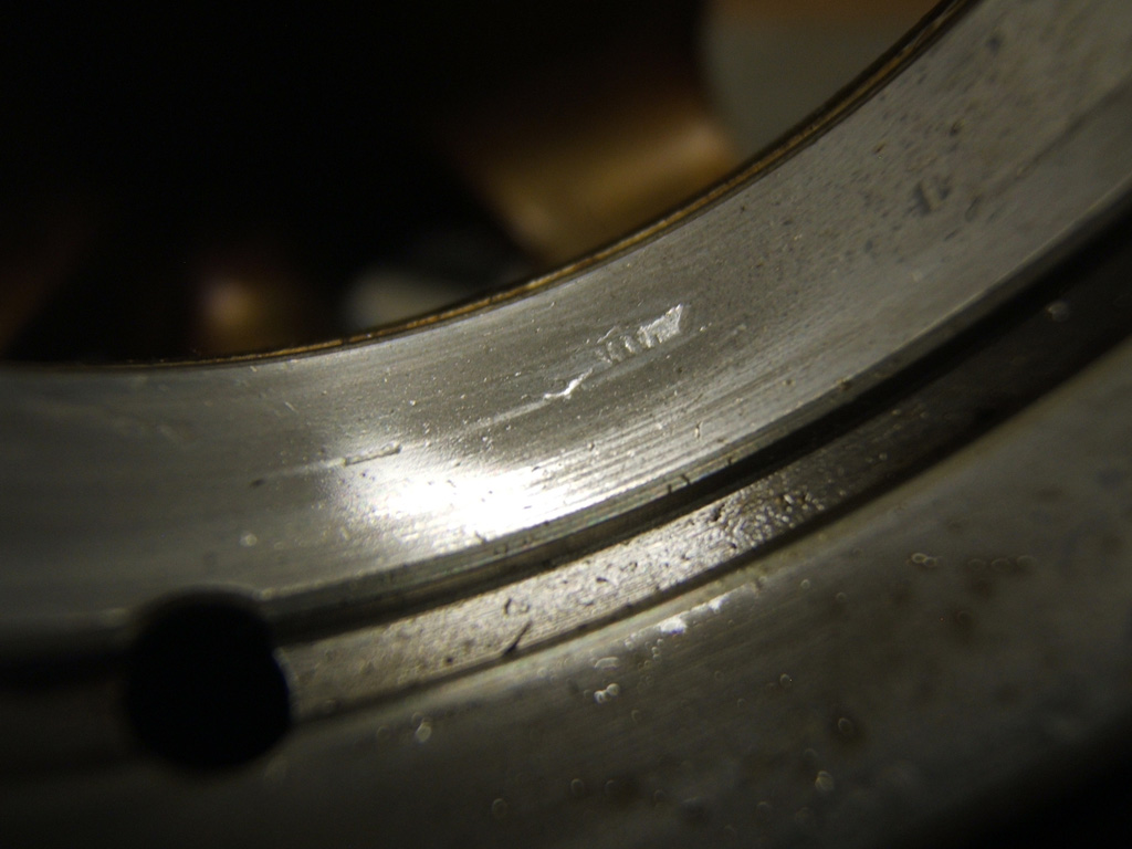
You couple that with the fact that all my numbers have been at the "new spec" really makes me think the Xado has done some restorative work. I mean I didn't rip into the motor before hand but I do know what I witnessed over time with the knocking, then I of course fucked myself and I know it. But with these bearings I inspected to go with what I personally witnessed, I think my personal skepticism has now been put to the wayside.
I don't expect anyone else to believe but I can say I personally do.
Plus also witnessing how it quieted my wife's knock down to where you can't hear it at all now.... Yeah. Interesting tribology stuff indeed.
It's time to pick up some more for both my tranny, and my wife's engine.
I was always noticing a bit of knocking when in drive through windows and after awhile, the knocking was actually going away. Then I got stupid and redlined it with the motor bone cold as some little kids really pissed me off one grumpy morning. So I blew some cold running rich exhaust in their faces as they had just went behind my car to sit against the wall after flipping me off for no apparent reason.
Needless to say, the knocking returned. After tonight, I could see why as I was to copper in all 4 rod big end bearings which you will see soon enough.
But here is the real kewl stuff. I saw examples that Xado provided of their stuff filling in scratches, but we all know marketing will put anything for sales, so since it was from Xado, the skepticism always nagged at the back of the mind.
Well check out these main bearing in the cap girdle from this motor... Definite hard core scratches are filled in. You can't feel the difference with your fingernail and you can tell there was some deep ones.
You couple that with the fact that all my numbers have been at the "new spec" really makes me think the Xado has done some restorative work. I mean I didn't rip into the motor before hand but I do know what I witnessed over time with the knocking, then I of course fucked myself and I know it. But with these bearings I inspected to go with what I personally witnessed, I think my personal skepticism has now been put to the wayside.
I don't expect anyone else to believe but I can say I personally do.
Plus also witnessing how it quieted my wife's knock down to where you can't hear it at all now.... Yeah. Interesting tribology stuff indeed.
It's time to pick up some more for both my tranny, and my wife's engine.
Last edited by TomCat39; 07-21-2015 at 06:35 PM. Reason: Optimizing Photo's
07-11-2015, 07:06 PM
#12
Hysterically Calm
Thread Starter
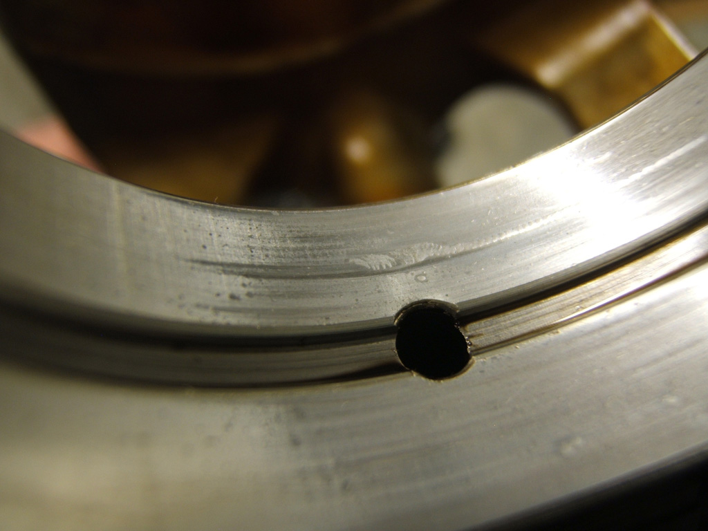
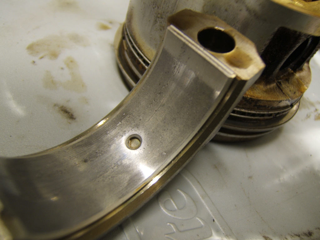
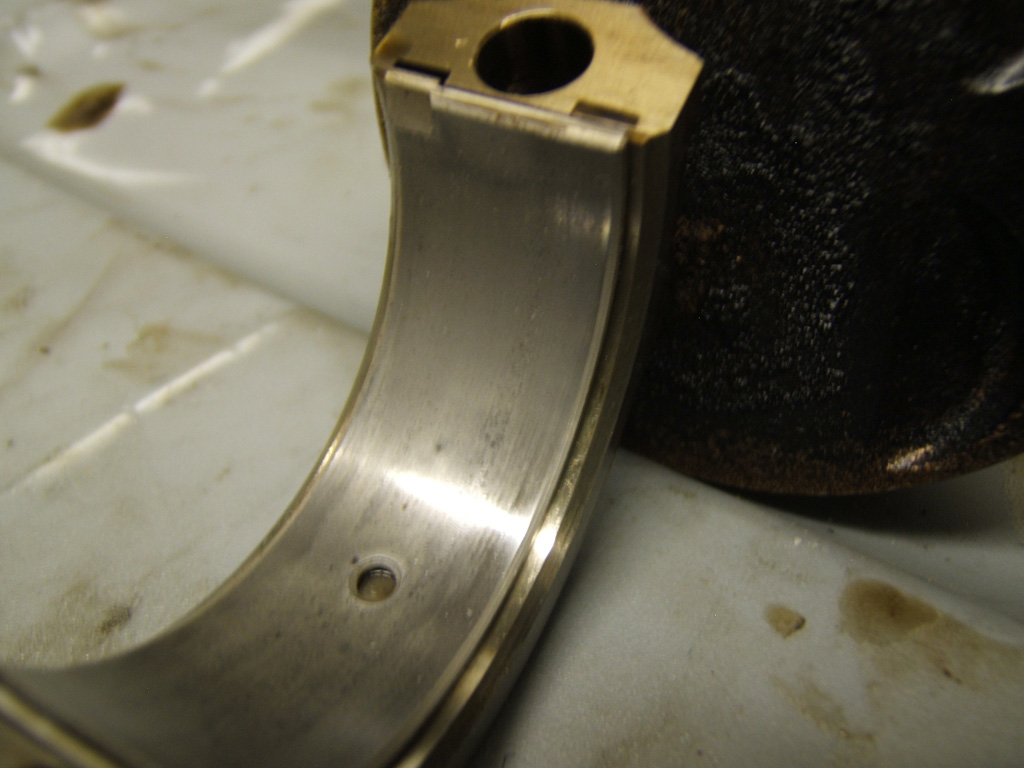
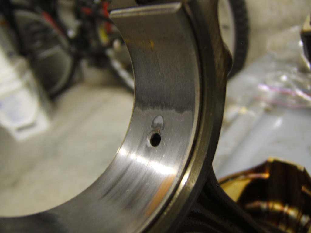
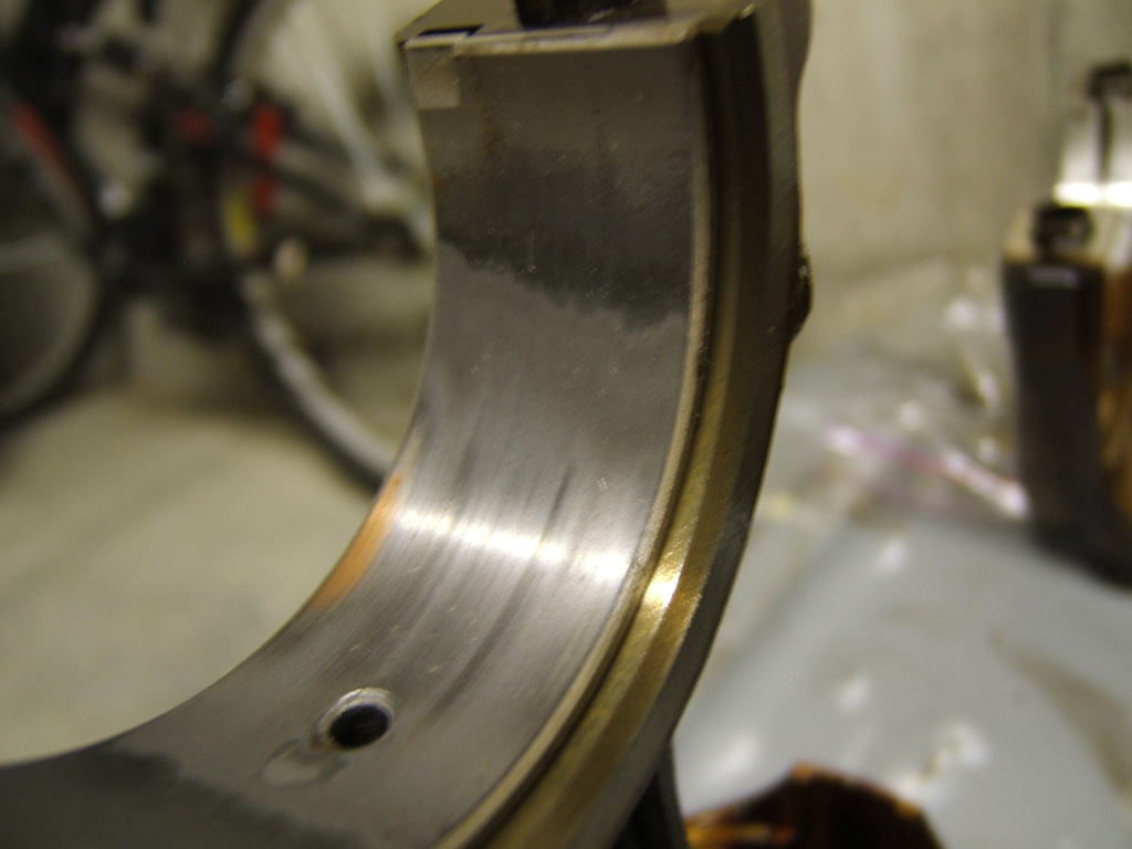
Here is the main bearings in the cap girdle #1, #2, #3, #4, and #5
And now the other half of the bearings that are in the block #1, #2, #3, #4, and #5

I also have the pics of the rod bearings which I will post up in a bit. I am being beckoned to head out for a bit so I will finish posting up tonight's work and findings a bit later once I'm back.
And with the rod pics, I'll also report my awesome crank inspection measurements for out of round and taper. All still within "new" spec as per the FSM. \m/ o,o \m/
And now the other half of the bearings that are in the block #1, #2, #3, #4, and #5
I also have the pics of the rod bearings which I will post up in a bit. I am being beckoned to head out for a bit so I will finish posting up tonight's work and findings a bit later once I'm back.
And with the rod pics, I'll also report my awesome crank inspection measurements for out of round and taper. All still within "new" spec as per the FSM. \m/ o,o \m/
Last edited by TomCat39; 07-21-2015 at 06:39 PM. Reason: Optimizing Photo's
07-11-2015, 08:56 PM
#13
Hysterically Calm
Thread Starter
Okay hear is the bearings from Rod #1 Cap is a little blurry but the cap bearings are in the best of shape so not missing much. You can definitely see the copper on the rod side bearing.
Now the bearings on #2.
Now the bearings on #2.
Last edited by TomCat39; 07-21-2015 at 06:42 PM. Reason: Optimizing Photo's
07-11-2015, 09:35 PM
#14
Hysterically Calm
Thread Starter
And now for Rod #3.
And last but not least, here is Rod #4.
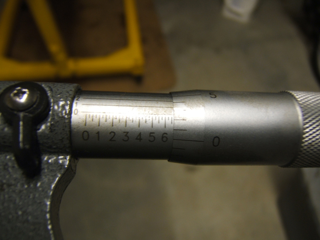
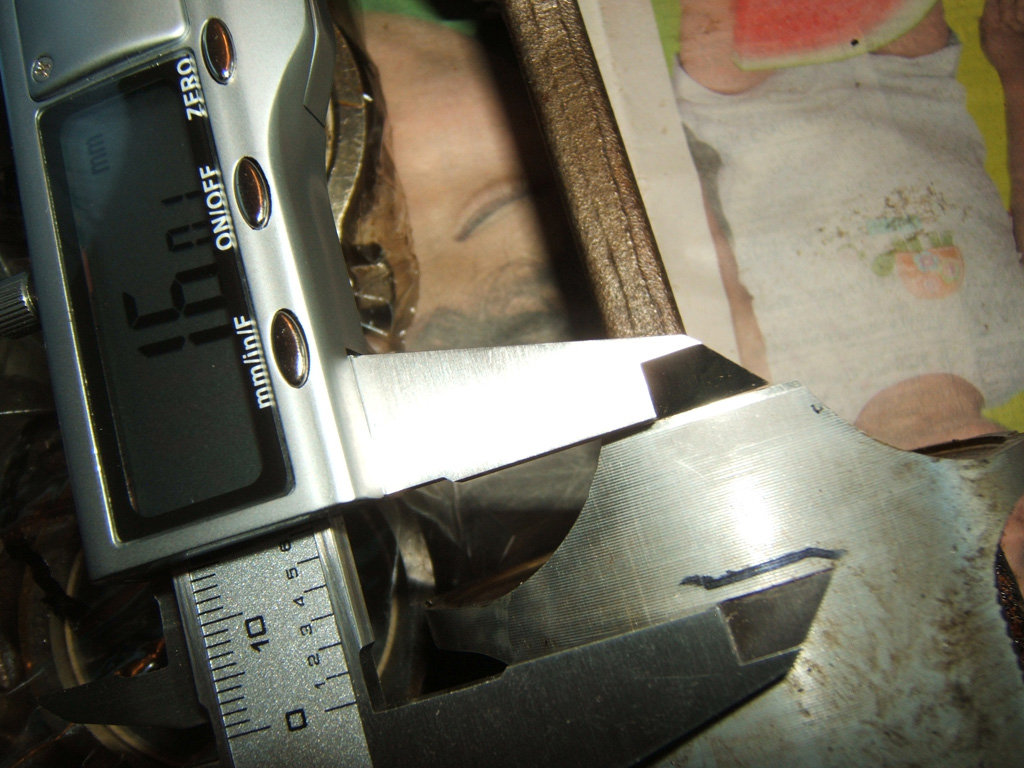
After taking pics, I broke out my 1-2 inch Micrometer with Vernier scale (10,000ths of an inch) an measured the x and y in the middle of each rod journal. The results:
#1 1.6522", 1.6521" - Out of round 0.0001"
#2 1.6523", 1.6523" - Out of round 0.0000"
#3 1.6524", 1.6524" - Out of round 0.0000"
#4 1.6521", 1.6522" - Out of round 0.0001"
The following pic is the measurement of #2 at 1.6523"
Then I moved onto the mains and got the following results:
#1 1.7775", 1.7777" - Out of round 0.0002"
#2 1.7776", 1.7777" - Out of round 0.0001"
#3 1.7776", 1.7776" - Out of round 0.0000"
#4 1.7775", 1.7774" - Out of round 0.0001"
#5 1.7774", 1.7774" - Out of round 0.0000"
Then we move onto the taper check. I only did one axis for the left and right side of each journal. I also didn't bother writing down the measurement results as they are right in line with the out of round results above. I just recorded the variance.
#1 - 0.0002" taper
#2 - 0.0002" taper
#3 - 0.0001" taper
#4 - 0.0001" taper
#5 - 0.0000" taper
By the FSM out of round when "new" will not be more than 0.0002" and the service limit is 0.0004". Mine are all within "new" spec.
Then taper says the difference in taper measurements will not be more than 0.0002" when "new" and service limit of 0.0004". Once again my taper is is within "new" spec.
The part that throws me a bit is I went to worldwidemetric.com and converted the inches to mm and found that 1.6524" = 41.9710mm yet spec says both rod and main journals are supposed to be 45mm. The mains measuring out to 1.7777" = 45.1536mm. This made me go hmmm so I will have to inspect the Z6 big end rod to my B7 big end rod and see if it matches up okay.
I'm also borrowing my friends dial bore gauge as I don't have one yet as well as his 2-3 or 3-4 inch micrometer. I will check the bore of the rod big end as well as the main bore and see if there is that much being absorbed by the bearings. As well as verify that the Z6 rod will mate with the B7 crank without issue.
Another tip my friend gave me for the D-series is what bolts work with the transmission motor side bell housing. Turns out the driver side motor mount is the same thread pitch and bolt diameter but longer to mount the engine. If you are pulling them at a salvage yard to also grab one of the nuts from the top two studs of the same mount, I believe it fits the bolt just fine. I forgot so I had to buy a bolt and nut for the one pass through on the motor for a few bucks. I also bought 9 nuts that easily slide over the driver side bolt for spacers. The bolts are so long that I couldn't cinch the block flush with the stand bracket. Here is a pic of the final result which works well to keep the block nice and snug to the stand:
Oh, and I forgot to get a pic of the skirt scuffing damage that I found on #1 I think it was. My other young mechanic buddy pointed out the piston slap sound when you blipped the throttle just right when I first got the car. Now with tear down, I've confirmed that he was 100% correct with diagnosing the sound and I know the sound myself now because of it. Could be done on a warm engine so I almost wonder if maybe when they did the head gasket with a leak gasket in the TSB and the new head bolts that they did a hone on the cylinders putting the P2W clearance a little far.
Dunno, the dial bore gauge measurements of the cylinders will give a better idea of things.
Now I wait for more tools.
Cheers and hope you all are enjoying this as much as I am going through it and documenting it. This "diary" will help keep all the facts and figures clean as I'm sure I'd lose something along the way otherwise.
Cheers
And last but not least, here is Rod #4.
After taking pics, I broke out my 1-2 inch Micrometer with Vernier scale (10,000ths of an inch) an measured the x and y in the middle of each rod journal. The results:
#1 1.6522", 1.6521" - Out of round 0.0001"
#2 1.6523", 1.6523" - Out of round 0.0000"
#3 1.6524", 1.6524" - Out of round 0.0000"
#4 1.6521", 1.6522" - Out of round 0.0001"
The following pic is the measurement of #2 at 1.6523"
Then I moved onto the mains and got the following results:
#1 1.7775", 1.7777" - Out of round 0.0002"
#2 1.7776", 1.7777" - Out of round 0.0001"
#3 1.7776", 1.7776" - Out of round 0.0000"
#4 1.7775", 1.7774" - Out of round 0.0001"
#5 1.7774", 1.7774" - Out of round 0.0000"
Then we move onto the taper check. I only did one axis for the left and right side of each journal. I also didn't bother writing down the measurement results as they are right in line with the out of round results above. I just recorded the variance.
#1 - 0.0002" taper
#2 - 0.0002" taper
#3 - 0.0001" taper
#4 - 0.0001" taper
#5 - 0.0000" taper
By the FSM out of round when "new" will not be more than 0.0002" and the service limit is 0.0004". Mine are all within "new" spec.
Then taper says the difference in taper measurements will not be more than 0.0002" when "new" and service limit of 0.0004". Once again my taper is is within "new" spec.
The part that throws me a bit is I went to worldwidemetric.com and converted the inches to mm and found that 1.6524" = 41.9710mm yet spec says both rod and main journals are supposed to be 45mm. The mains measuring out to 1.7777" = 45.1536mm. This made me go hmmm so I will have to inspect the Z6 big end rod to my B7 big end rod and see if it matches up okay.
I'm also borrowing my friends dial bore gauge as I don't have one yet as well as his 2-3 or 3-4 inch micrometer. I will check the bore of the rod big end as well as the main bore and see if there is that much being absorbed by the bearings. As well as verify that the Z6 rod will mate with the B7 crank without issue.
Another tip my friend gave me for the D-series is what bolts work with the transmission motor side bell housing. Turns out the driver side motor mount is the same thread pitch and bolt diameter but longer to mount the engine. If you are pulling them at a salvage yard to also grab one of the nuts from the top two studs of the same mount, I believe it fits the bolt just fine. I forgot so I had to buy a bolt and nut for the one pass through on the motor for a few bucks. I also bought 9 nuts that easily slide over the driver side bolt for spacers. The bolts are so long that I couldn't cinch the block flush with the stand bracket. Here is a pic of the final result which works well to keep the block nice and snug to the stand:
Oh, and I forgot to get a pic of the skirt scuffing damage that I found on #1 I think it was. My other young mechanic buddy pointed out the piston slap sound when you blipped the throttle just right when I first got the car. Now with tear down, I've confirmed that he was 100% correct with diagnosing the sound and I know the sound myself now because of it. Could be done on a warm engine so I almost wonder if maybe when they did the head gasket with a leak gasket in the TSB and the new head bolts that they did a hone on the cylinders putting the P2W clearance a little far.
Dunno, the dial bore gauge measurements of the cylinders will give a better idea of things.
Now I wait for more tools.
Cheers and hope you all are enjoying this as much as I am going through it and documenting it. This "diary" will help keep all the facts and figures clean as I'm sure I'd lose something along the way otherwise.
Cheers
Last edited by TomCat39; 07-21-2015 at 06:47 PM. Reason: Optimizing Photo's
07-11-2015, 09:41 PM
#15
Hysterically Calm
Thread Starter
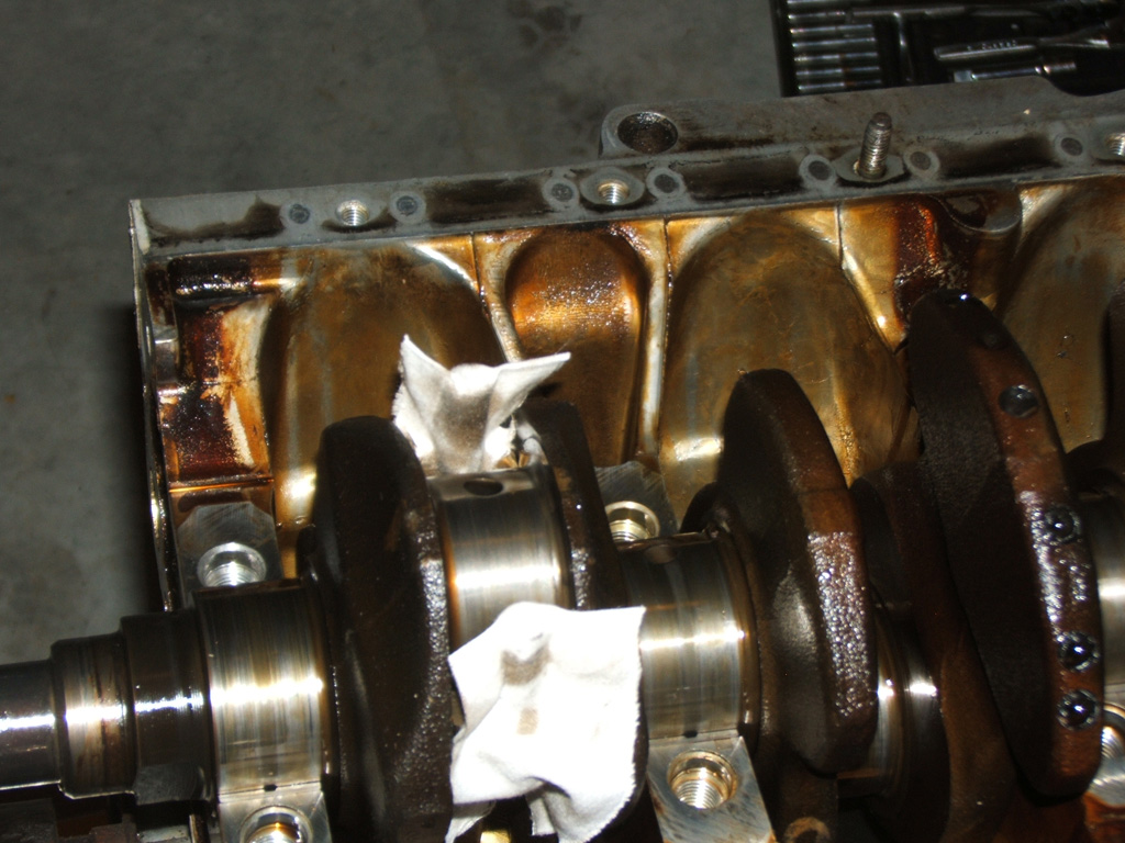
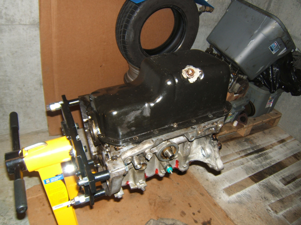
Oh and I forgot to show my buttoning up for the night.
The workshop I'm doing this in is accessible by all strata members in my building so since I can't be sure some numb nut isn't going to leave well enough alone when I'm not there. If they go in and flip the motor over, the last thing I want is for the crank to go clanging to the ground.
So I put the girdle back on and put in 6 bolts but not tight, just to where it just grabs. Then put the oil pan on to keep dust and dirt out with 1 nut and 2 bolts.
Once the measuring is done, I can get it all washed up and go from there.
Cheers for the second time tonight. 
The workshop I'm doing this in is accessible by all strata members in my building so since I can't be sure some numb nut isn't going to leave well enough alone when I'm not there. If they go in and flip the motor over, the last thing I want is for the crank to go clanging to the ground.
So I put the girdle back on and put in 6 bolts but not tight, just to where it just grabs. Then put the oil pan on to keep dust and dirt out with 1 nut and 2 bolts.
Once the measuring is done, I can get it all washed up and go from there.
Cheers for the second time tonight.
Last edited by TomCat39; 07-21-2015 at 06:49 PM. Reason: Optimizing Photo's
07-12-2015, 07:31 AM
#16
GDD's Resident Derp
You have some really beautiful engine innards, TomCat39.
07-12-2015, 09:02 AM
#17
Hysterically Calm
Thread Starter
Yep it's official, found another mistake in the FSM in the SPECIFICATION section.
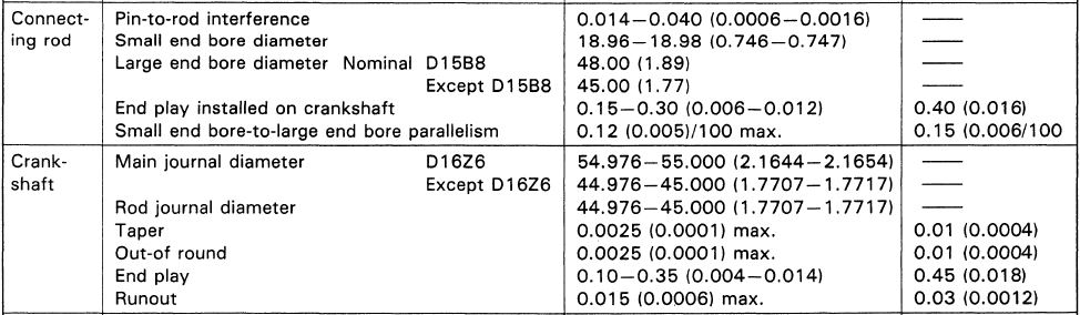
Under Connecting Rod, Large End bore diameter should say D16Z6/Except D16Z6 not D15B8 like it does. And then under Crank shaft the Rod journal diameter should be two lines, one for "Except D16Z6" 44.976-45.00 and then the second line would be D16Z6 47.976-48.000.
I broke out my calipers last night and pulled out the Z6 Rods my buddy gave me and sure enough, the B7 Big End bore is just shy of 45mm and the Z6 Big End bore is just shy of 48mm.
So that put's a kink into my original plans and I have some more investigating to do. Really did not want to spend high dollars on a custom race crank but I suppose if I did, I could stroke it out with the smaller compression height pistons and still get the higher compression ratio....
The other thing I might look into, is seeing what the D15B2 stock rods look like. If they are a little beefier over the B7 then I might feel a little more confident taking the rpm up to 8000 like I would like.
Also of note, on the crankshaft section, they show out of round and taper in the "new" column to be 0.0001" while in the inspection section it says 0.0002". Service limit of 0.0004" matches in both areas.
 07-16-2015, 08:25 PM
#20
What would Chente do?
Join Date: Nov 2000
Location: socali
Posts: 2,934
Likes: 0
Received 0 Likes
on
0 Posts
if you want to keep it "nothing fancy" and cheap, work with what you got. Y8 head is always nice but adds cost and more work on your end.
Google d15beast7. Very simple and peppy motor.
cliffs*
Mill head .060"
use z6 intake manifold w/ b series t/body
use a6 cam with y7/y8 cam gear for proper index
Your 95 head should have come with surplus a6 valve springs already from honda and the b7 and a6 heads share same casting.
mild port and polish if you want and ebay header and you are done.
tranny wise, find an EX/Si trans for better gearing. peace
07-16-2015, 09:21 PM
#21
Hysterically Calm
Thread Starter
if you want to keep it "nothing fancy" and cheap, work with what you got. Y8 head is always nice but adds cost and more work on your end.
Google d15beast7. Very simple and peppy motor.
cliffs*
Mill head .060"
use z6 intake manifold w/ b series t/body
use a6 cam with y7/y8 cam gear for proper index
Your 95 head should have come with surplus a6 valve springs already from honda and the b7 and a6 heads share same casting.
mild port and polish if you want and ebay header and you are done.
tranny wise, find an EX/Si trans for better gearing. peace
Google d15beast7. Very simple and peppy motor.
cliffs*
Mill head .060"
use z6 intake manifold w/ b series t/body
use a6 cam with y7/y8 cam gear for proper index
Your 95 head should have come with surplus a6 valve springs already from honda and the b7 and a6 heads share same casting.
mild port and polish if you want and ebay header and you are done.
tranny wise, find an EX/Si trans for better gearing. peace
I know the Y8 head is going to add cost just in the tuning aspect alone. I also am planning on a stepped up Crower cam for the Y8 head, only one step up now that I have to stick with the stock rods and pistons so my CR will stay at the standard Y8/B7 combo.
Already have the header and I'm thinking about the 60mm throttle body from the H22 accords.
Plus I have some measurements and calculations to do on the Y8 IM to compare with the Z6 IM I've already measured. Don't feel like dropping 745+ for the latest S2 Ultra IM. Even though it sure looks spiffy.
I was looking at about 1500 for the motor, now it's looking more like about 1000 after tuning.
So... Nothing fancy.
07-19-2015, 06:21 PM
#22
Hysterically Calm
Thread Starter
Today I sat down and measured my pistons while I wait for a 0.0001" dial indicator for the Dial Bore Gauge tool. I noticed the FSM does 10,000ths of an inch on the bores so I don't like the idea of approximations based on how far in between 0.001 and 0.002" on the 0.001" dial indicator.
One of the things I didn't care for was trying to make sure I was the right height on the piston skirt as well as centered on the peak of the skirt.
So I am fortunate to have a decent guillotine paper cutter that I was able to cut a nice piece of cardboard stock with. The cardboard stock allowed me to rest the micrometer at the proper height as I focused on the centering for measurements. This provided a solid result for all four pistons.
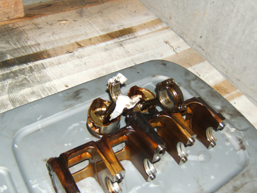
So here are the 4 pistons and one garbage piston in behind.
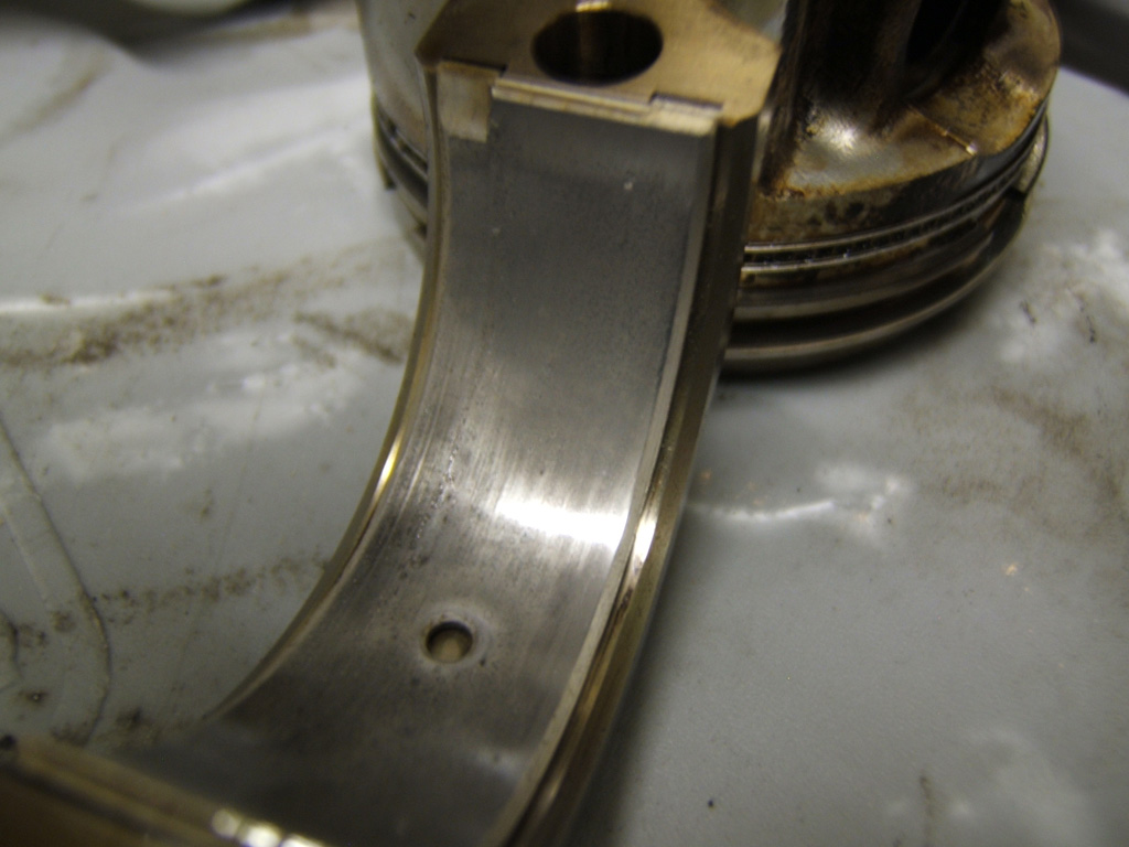
Then we have the junker piston to use for marking etc. I may also use it to hold bearings to dremel the oil holes but haven't decided on that yet. I noticed the oil holes on the mains are quite a bit larger than the rods and was thinking that with the upped RPM range, I might want to have the same size oil holes on the rod bearings as the mains.
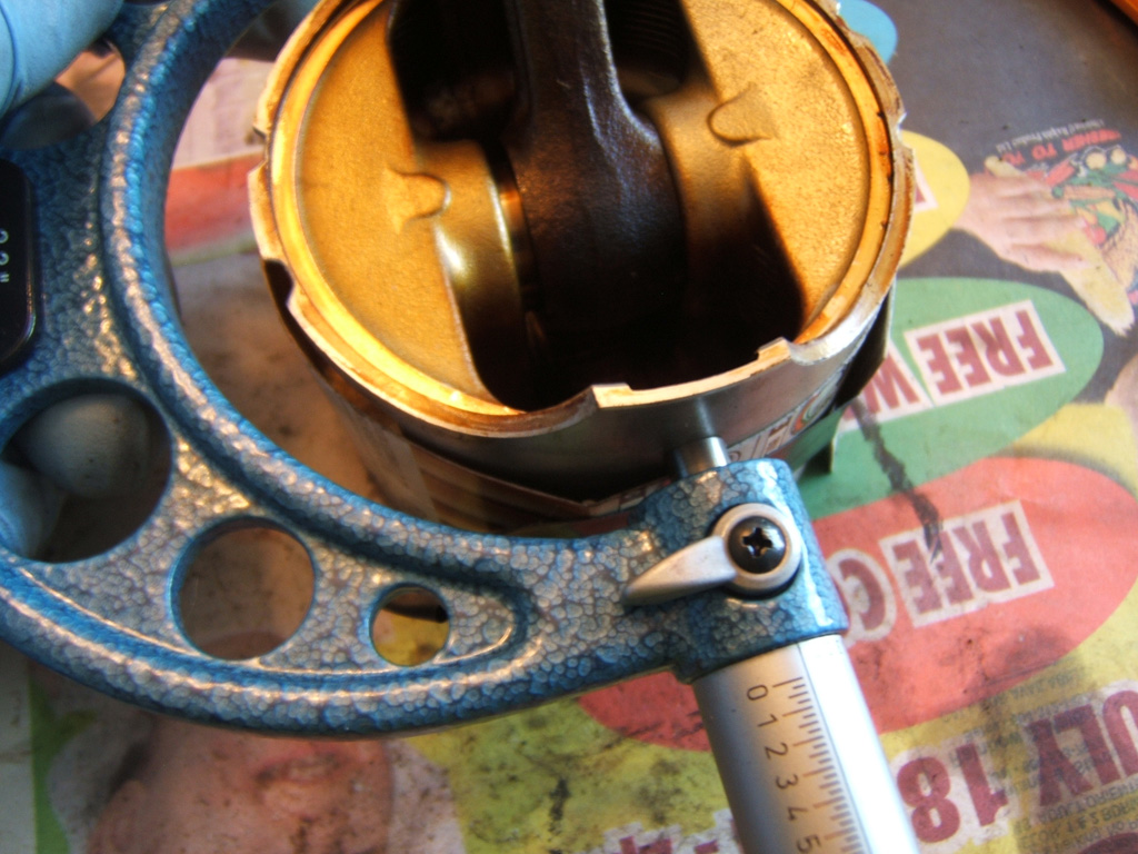
Now we can see my mark is just above where I want the micrometer sitting at the 16mm mark as per FSM.
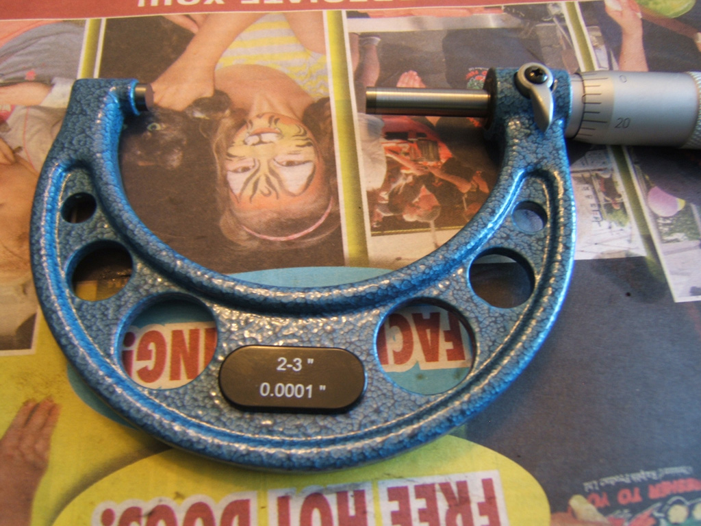
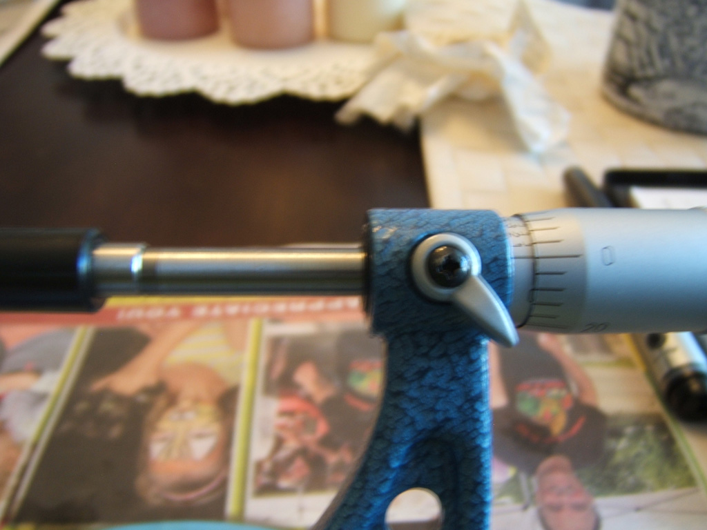
Here is the 2-3" micrometer and showing it calibrated.
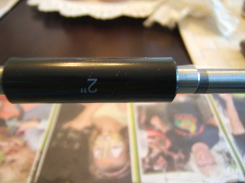
And now for my handy dandy height management tool. I wrapped this piece around the pistons and have a nice piece of tape hold it in place. This put the micrometer in the perfect height on the piston skirt within .5 mm. Based on the light markings on the skirt after sliding the micrometer over the skirt, it looked like I just about perfectly nailed the 16mm mark.
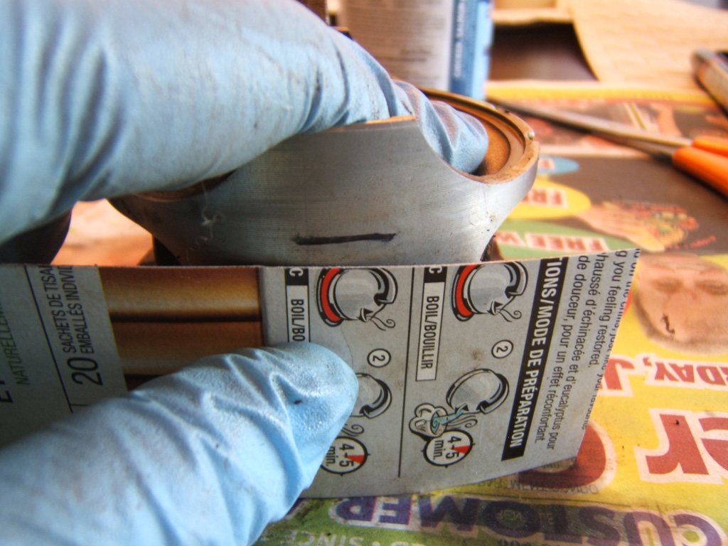
You have to remember the thickness of the micrometer shafts. With that it puts the center of the shaft right about where it should be and I could then focus on the centering on the horizontal line of the skirt.
One of the things I didn't care for was trying to make sure I was the right height on the piston skirt as well as centered on the peak of the skirt.
So I am fortunate to have a decent guillotine paper cutter that I was able to cut a nice piece of cardboard stock with. The cardboard stock allowed me to rest the micrometer at the proper height as I focused on the centering for measurements. This provided a solid result for all four pistons.
So here are the 4 pistons and one garbage piston in behind.
Then we have the junker piston to use for marking etc. I may also use it to hold bearings to dremel the oil holes but haven't decided on that yet. I noticed the oil holes on the mains are quite a bit larger than the rods and was thinking that with the upped RPM range, I might want to have the same size oil holes on the rod bearings as the mains.
Now we can see my mark is just above where I want the micrometer sitting at the 16mm mark as per FSM.
Here is the 2-3" micrometer and showing it calibrated.
And now for my handy dandy height management tool. I wrapped this piece around the pistons and have a nice piece of tape hold it in place. This put the micrometer in the perfect height on the piston skirt within .5 mm. Based on the light markings on the skirt after sliding the micrometer over the skirt, it looked like I just about perfectly nailed the 16mm mark.
You have to remember the thickness of the micrometer shafts. With that it puts the center of the shaft right about where it should be and I could then focus on the centering on the horizontal line of the skirt.
Last edited by TomCat39; 07-21-2015 at 06:53 PM. Reason: Optimizing Photo's
07-19-2015, 06:43 PM
#23
Hysterically Calm
Thread Starter
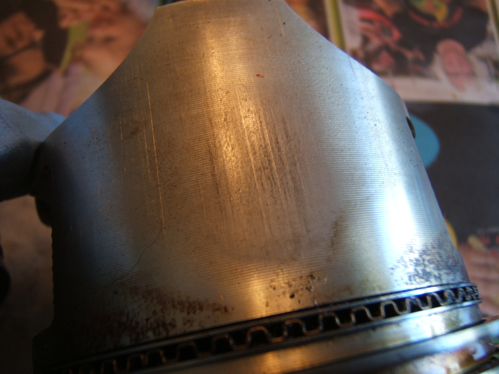
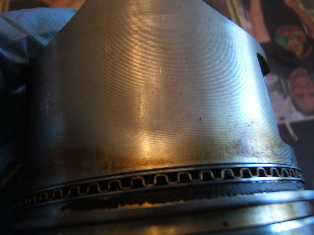
So this scuffing can be seen on all 4 pistons and as can be seen is on the exhaust side. Not severe so as one person pointed out to me, it could very well be from an over heat. I did the buy the car with the knowledge it had a head gasket job done and the leak gasket and new head bolts as per the TSB were used. So it very well did over heat once. Quality work was done to repair it but the bottom end did have worn bearings which wasn't touched.
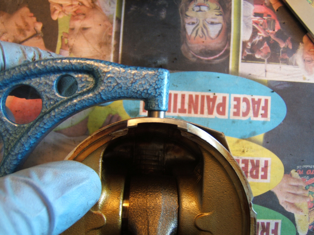
This is where I trimmed the cardboard stock to be so the micrometer posts landed in the proper spots.

And here is how I was able to purely focus on pinpointing the center of the skirt on the horizontal line using the wrap around card stock.
And this last pic shows the junker piston with my marks on it showing very little blow by even though it was from a 274,000 KM car while my piston shows browning below the rings on the skirt.
The final results of the measurements are:
1) 2.9525"
2) 2.9526"
3) 2.9524"
4) 2.9522"
Converting that over we have:
1) 74.9935 mm
2) 74.9960 mm
3) 74.9910 mm
3) 74.9859 mm
Now I wait for the 0.0001" dial indicator so I can measure bores.
Also someone brought forward a pretty good idea to me that I think I will work on doing. It was mentioned to me that the picture sizing isn't very phone friendly so might be reducing view-ability. I think I will re-save all the pictures, optimize them for the web (with adobe photoshop) and re-upload them.
I think optimal size for the photo's will be 1024x768 and then use the web optimization feature of photoshop to reduce file size yet work at keeping the most quality to the photos.
Look forward to a better loading thread soon.
This is where I trimmed the cardboard stock to be so the micrometer posts landed in the proper spots.
And here is how I was able to purely focus on pinpointing the center of the skirt on the horizontal line using the wrap around card stock.
And this last pic shows the junker piston with my marks on it showing very little blow by even though it was from a 274,000 KM car while my piston shows browning below the rings on the skirt.
The final results of the measurements are:
1) 2.9525"
2) 2.9526"
3) 2.9524"
4) 2.9522"
Converting that over we have:
1) 74.9935 mm
2) 74.9960 mm
3) 74.9910 mm
3) 74.9859 mm
Now I wait for the 0.0001" dial indicator so I can measure bores.
Also someone brought forward a pretty good idea to me that I think I will work on doing. It was mentioned to me that the picture sizing isn't very phone friendly so might be reducing view-ability. I think I will re-save all the pictures, optimize them for the web (with adobe photoshop) and re-upload them.
I think optimal size for the photo's will be 1024x768 and then use the web optimization feature of photoshop to reduce file size yet work at keeping the most quality to the photos.
Look forward to a better loading thread soon.
Last edited by TomCat39; 07-21-2015 at 06:56 PM. Reason: Optimizing Photo's
07-19-2015, 06:45 PM
#24
Another easy way to manage your pictures - upload them to imgur, then use their autoresizing tool. That's what I do, and no one has ever complained about image sizes 
07-19-2015, 07:14 PM
#25
Hysterically Calm
Thread Starter