
Clutch safety switch wire location?
 09-15-2009, 03:36 PM
#1
Member
Thread Starter
Join Date: Apr 2004
Location: Bucks County
Posts: 1,008
Likes: 0
Received 0 Likes
on
0 Posts
does anyone know where these 2 wires lead to? i need to access these wires so i can tap into one, but its such a pain to get your hands in there, i want to know if theres a location where these wires go that is not hard to get too? i have a 92 CX no cruise control or ac
 09-15-2009, 08:08 PM
#6
Honda-Tech Member
Join Date: Aug 2009
Location: Delaware
Posts: 778
Likes: 0
Received 0 Likes
on
0 Posts
Sorry man not much help but mine was removed from the original location by prev. owner, who used it as a pretty ghetto kill switch. I redid it and saw the wires went up under the dash somewhere in the harness. Now I have a momentary switch mounted somewhere that I just flip up when I start the car. This is in my sol btw.
09-15-2009, 08:22 PM
#7

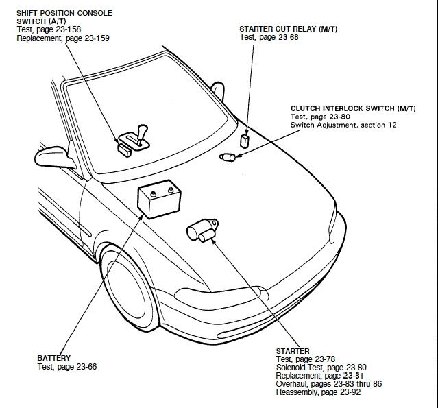
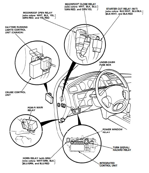
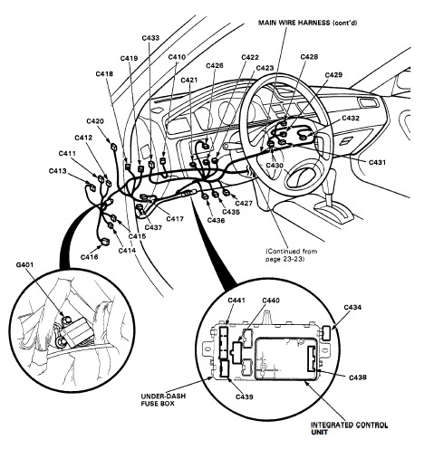
The Blu/Blk power wire runs to the starter cut relay under the dash and the Blk ground wire is attached to the frame behind the driver's kick panel.
Trending Topics

 09-16-2009, 06:23 PM
#10
Member
Thread Starter
Join Date: Apr 2004
Location: Bucks County
Posts: 1,008
Likes: 0
Received 0 Likes
on
0 Posts
great pictures ronJ, now from my understanding the clutch switch sends a negative output signal correct? if this is correct, then how or where can i find a positive 12 volt output signal when the clutch is pushed in?

09-16-2009, 06:45 PM
#12
09-16-2009, 06:55 PM
#13
Member
Thread Starter
Join Date: Apr 2004
Location: Bucks County
Posts: 1,008
Likes: 0
Received 0 Likes
on
0 Posts
WOT Box Installation Instructions
Connector Pinout
Pin Color AWG Name Description
1 Yellow 18 RPM Connect to Fuel Injector Drive Signal or Ignition Control Signal (varies by car model)
2 Black 18 Ground Connect to chassis ground
3 Black 16 Power Out Connect to ignition coil power wire going towards the ignition coils.
4 Blue 18 APP Connect to Accelerator Pedal Position Sensor or TPS (varies by car model)
5 Green 18 Clutch Connect to Clutch Pedal Position Switch
6 Red 16 Power In Connect to ignition coil power wire going away from the ignition coils.
09-16-2009, 06:57 PM
#14
Member
Thread Starter
Join Date: Apr 2004
Location: Bucks County
Posts: 1,008
Likes: 0
Received 0 Likes
on
0 Posts
Figure I: Installation schematic
1. Disconnect the battery negative terminal.
2. Pick out a location to mount the WOT Box. The WOT Box must be installed inside the passenger
compartment since it is not waterproof. Additionally, you will want to make the WOT Box accessible to the
driver, due to the fact that setting the 2‐step RPM will require holding down the clutch pedal while holding
the button on the WOT Box.
3. Locate a harness pass‐through on the firewall accessible from the passenger compartment. Some of these
are grommets that have enough room for extra wires to be passed through next to the existing harness.
Some have a tightly fitting skirt that the harness passes through that does not allow for extra wires. If yours
is the second, carefully poke a new hole in the skirt using a sharp object, such as a screwdriver. Be careful
not to damage other wires already in the grommet, and make sure that the hole is only large enough for
the red/black pair and yellow wire from the WOT box to pass through. If it is too large, water can leak in.
4. Bundle the WOT Box 18 AWG YELLOW and 16 AWG RED / BLACK paired wires using electrical tape. Using a
coat hanger or other sharp object, pull the bundle through the grommet in the firewall.
5. Route the connector end of the wiring harness to the desired mounting point. Be careful to avoid sharp
metal objects and pinch points. Leave enough of the harness in the passenger compartment to make the
WOT Box easy to get to, but not an excessive amount.
6. Locate the ignition coil wiring harness, usually on the driver's side of the cylinder head, near the cam shafts.
Remove some of the split loom tubing and tape to expose the wires.
7. Locate the ignition coil power wire(s). Refer to the Table #1 below to identify the wire colors for your
vehicle. If your vehicle has more than one ignition coil, either locate the splice point where the power wires
from all of the ignition coils come together at one point, or cut into all of the ignition coil power wires. Cut
the wire(s) and strip both ends of the wire(s) about 5/8".
8. Split apart about 6" of the 16 AWG RED / BLACK wire from the WOT Box. Strip the ends of the wires and
slide two pieces of provided heat shrink tubing over the wires. Connect the 16 AWG RED wire from the
WOT Box to the wire(s) previously stripped that are going away from the ignition coils. Connect the 16
AWG BLACK wire to the wire(s) previously stripped that are going towards the ignition coil(s). Solder the
connection and use the provided heat shrink tubing to cover the connection. Tape up the harness with
electrical tape. Recover the harness with the split loom tubing and wrap with electrical tape.
9. Locate the wire specified in Table #2. You may tap into this wire at the device itself or at the ECU,
whichever option is more convenient for you. This wire doesn’t need to be interrupted, but rather a signal
read from it. Solder the 18 AWG YELLOW wire from the WOT Box to this wire, ensuring that the original
connectivity of the wire is maintained. If the original wire is cut and later rejoined to do this (preferred),
use the included heat shrink tubing to seal the splice. If not, cover the solder joint with electrical tape.
10. Secure all of the under‐hood WOT Box wires using the provided zip ties. Be sure to route the wires away
from heat sources and sharp objects that may damage them. This completes the under‐hood portion of
the installation.
11. Back in the passenger compartment, locate the Accelerator Pedal Position Sensor. It is at the gas pedal.
Disconnect the connector.
12. Locate the Accelerator Pedal Position Sensor #1 signal wire. Or if your car is not drive by wire, you will tap
into the Throttle Position Sensor. You may tap into this wire at the accelerator pedal or throttle position
sensor itself or at the ECU, whichever option is more convenient for you. Refer to Table #3 below to
identify the wire colors for your vehicle. Once again, this wire doesn’t need to be interrupted, but merely
“tapped into.” Solder the 18 AWG BLUE wire from the WOT Box to this wire, ensuring the original
connectivity of the wire. If the original wire is cut and later rejoined to do this (preferred), use the included
heat shrink tubing to seal the splice. If not, cover the solder joint with electrical tape.
13. Locate the Clutch Pedal Position Switch. Disconnect the connector to make the harness easier to access.
14. Locate the Clutch Pedal Position Switch signal wire. Refer to Table #4 below to identify the wire colors for
your vehicle. You may tap into this wire at the Clutch Pedal Position switch itself or at the ECU, whichever
option is more convenient for you. Refer to the table below to identify the wire colors for your vehicle.
Once again, this wire will keep its original connections, and simply gain a new one. Solder the 18 AWG
GREEN wire from the WOT Box to the Clutch Pedal Position Switch (CPP) wire. If the original wire is cut and
later rejoined to do this (preferred), use the included heat shrink tubing to seal the splice. If not, cover the
solder joint with electrical tape. Reconnect the CPP connector.
15. Locate a good chassis ground point near where you plan on installing the WOT Box. Try to keep the wire
run as short as possible. It should be under 2’ away, if possible. Next, cut the 18 AWG BLACK wire from the
WOT Box to length. Strip the wire and solidly crimp on the provided ground lug connection. Solder the
ground wire to the ground lug. Connect this ground lug to the chassis. Make sure the metal where you
attach the ground lug is clean, unpainted and free of rust. Use sand paper to prepare the surface, if
needed.
16. Connect the WOT Box to the harness and tuck the WOT Box into the fuse panel. Re‐install the battery and
all the plastic trim that was removed during the installation. The installation is complete. Proceed to the
testing section below.
09-16-2009, 08:04 PM
#16
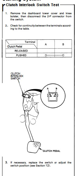
The switch referred to in your instruction manual is for the clutch cruise control (cc) switch rather than the clutch starter switch. The difference is that the cc switch is closed with the clutch pedal up whereas the starter switch is open with the clutch pedal up. The WOT Box manual does not suggest an alternate installation without cc. You might want to make a thread inquiring about how to install the Box in a 92-95 Civic lacking cc.
09-16-2009, 08:14 PM
#18
09-16-2009, 08:24 PM
#20
Member
Thread Starter
Join Date: Apr 2004
Location: Bucks County
Posts: 1,008
Likes: 0
Received 0 Likes
on
0 Posts
i can use it up or down, in the program when i connect the laptop to the wot box i can click inverted clutch signal, so while its up it can switch it to down or vise versa so am i in the clear still? or still no way?
09-16-2009, 08:26 PM
#21
Honda-Tech Member
Join Date: Jan 2008
Location: WA
Posts: 1,753
Likes: 0
Received 0 Likes
on
0 Posts
Then nevermind, just use the blue/blk wire from the clutch switch!
The clutch switch as it sits in the car is OPEN in the up position and GND in the down position.
The clutch switch as it sits in the car is OPEN in the up position and GND in the down position.
09-16-2009, 08:29 PM
#22
Member
Thread Starter
Join Date: Apr 2004
Location: Bucks County
Posts: 1,008
Likes: 0
Received 0 Likes
on
0 Posts
i heard fuse 18 at the fuse box underdash when clutch held in sends a positive signal and when released opens?
09-16-2009, 08:31 PM
#25
Again, my concern about using the Blu/Blk wire is the apparent need for a 1K Ohm resistor upstream of the switch and Box. I don't know how this resistor would affect activation of the starter cut relay, starter solenoid, and starter. Maybe somebody can give you a more definitive answer.