
99 DX/D16Z6 swap -- Alternator is not charging
 11-08-2010, 06:34 AM
#1
Honda-Tech Member
Thread Starter
Join Date: Oct 2008
Posts: 24
Likes: 0
Received 0 Likes
on
0 Posts
Hi, this may be fun.
I bought a '99dx (D16Y7) with a D16Z6 swap. From what I can tell, the car is still using the '99 alternator. I drew this conclusion because the alternator has a square connector instead of a round connector. Is that correct?
I'm currently showing code 17 & 20 on my P28 (VSS + ELD). The VSS is brand new, and I have a 1y/o Yellow Top Optima and alternator (again the one with the square connector).
My alternator is not charging, and fuse #15 under the dash is not blown. But, when I pull the fuse, code 17 + 20 clear, but then I don't have a speedo; still no charging.
Obviously there is an issue with the charging circuit.
I'm having a hard time finding what pinouts are for a '99 alternator and a '95 alternator. I'd like to confirm that 1) the wires are connected to the correct pins on the ECU, and 2) perhaps a wire somewhere in the harness is shorting to ground or something. Does anyone know what the pins are?
My Haynes manual for '95 says:
Pin 1: WHT/YEL to pin A16 on ECU
Pin 2: BLU to pin D9 on ECU
Pin 3: BLK/YEL to junction connector C415 (which is under the intake manifold BTW)
Pin 4: WHT/BLU to dash F/B (presumably fuse box, presumably fuse #15?)
The wires currently on the harness (original D16Y7 harness) to the alternator connector are:
Pin 1: BLK/YEL to junction C415 (blue connector under intake manifold; verified with multi-meter)
Pin 2: WHT/GRN to ?
Pin 3: WHT/ BLU to ?
Pin 4: WHT/ RED to ?
Can anyone verify what each of these wires SHOULD be connected to?
I have a Chiltons manual for '99, but it doesn't seen to contain alternator pinout information like the Haynes manual does. I'll pick up a Haynes manual for a '99 as well.
I'm gonna bring teh alternator and battery to the parts store and have them tested while I'm there picking up that Haynes manual.
I had to call in to work since my car isn't running, so hopefully I can get this issue(s) resolved today.
Thanks for any insight anyone can shed.
BTW, I'm subscribing to this thread so I can get instant emails when it's updated. If I don't hear from anyone, I'll update this thread as I find more information.
Thanks!
 11-08-2010, 08:12 AM
#3
Honda-Tech Member
11-08-2010, 08:18 AM
#4
Honda-Tech Member
Thread Starter
Join Date: Oct 2008
Posts: 24
Likes: 0
Received 0 Likes
on
0 Posts
Hi,
Thanks for the reply. So your saying it doesn't matter if I have an alt for a '95 or a '99; AND that each wire on each respective alternator connects to the same pins on the ECU regardless of year or type (Mitsu or Nipondenso)?
I'm also trying to confirm that the alternator wirirng for the ECU is correct. I've found quite a few other circuits on the ECU that were improperly wired (kid was a complete hack, which is why this car was 'free'), so I'm basically doing a few things at once here.
I just want to verify for 100% certainty that this charging circuit is indeed wired properly. I also want to verify that none of these wires are shorting to ground and tripping the ELD code.
Before the alternator stopped charging, when the engine was warm, the idle would dip from 750 to about 525 for about one second, then rebound to 750 for one second; dip, rebound, dip, rebound until you started driving again. Theoretically, I understand that the idle would dip momentarily as the alternator began charging, creating additional load on the engine; but then the engine should compensate and restore to 750rpm...right?
-TANGENT-
Regarding code 17 (VSS): I replaced the sensor, verified wiring is correct, verified none are shorted; yet it's still tripping code 17. Thus, I'm led to believe code 17 may be a byproduct of some other wiring error/ issue. Any ideas?
11-08-2010, 09:08 AM
#5
Honda-Tech Member
Thread Starter
Join Date: Oct 2008
Posts: 24
Likes: 0
Received 0 Likes
on
0 Posts
Okay, I'm leaving to drive my wife to work and have the alternator and battery tested...
I also confirmed the wiring from the alternator:
WHT/ RED has no continuity to ground, and connects to pin D9 (ALTFR) on my P28.
WHT/ GRN has no continuity to ground, and connects to pin A16 (ALTC).
WHT/ BLU has no continuity to ground, but I don't know where the wire goes...I'll try and track that down, unless someone knows off-hand?
BLK/ YEL has continuity to ground, and connects to pin 2 on the big blue connector under the intake manifold.
BTW- anyone happen to know where I can find a list of what those various pins go to on the big blue and gray connectors under the intake manifold? I figured some one, but there are others I'm a little confused about.
Thanks!
11-08-2010, 09:21 AM
#6

If the alternator tests fine:
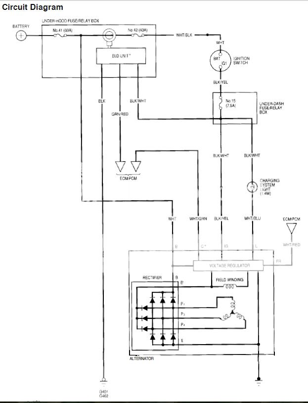
1) Check whether the Blk/Yel wire terminal in the alternator plug has battery voltage with the key in ON(II).
2) Voltage/amps produced by the alternator is sent to the hood fuse box on the large Wht wire connected to the alternator. Is the Wht wire connected and clean and tight at both the alternator and hood fuse box? Does the Wht wire have low resistance (Ohms)? What voltage to body ground do you measure at the Wht wire terminal connected to the hood fuse box when the engine is idling and what is the voltage across the battery terminals under this condition?
11-08-2010, 10:10 AM
#7
Honda-Tech Member
Thread Starter
Join Date: Oct 2008
Posts: 24
Likes: 0
Received 0 Likes
on
0 Posts
If the alternator tests fine:
1) Check whether the Blk/Yel wire terminal in the alternator plug has battery voltage with the key in ON(II).
2) Voltage/amps produced by the alternator is sent to the hood fuse box on the large Wht wire connected to the alternator. Is the Wht wire connected and clean and tight at both the alternator and hood fuse box? Does the Wht wire have low resistance (Ohms)? What voltage to body ground do you measure at the Wht wire terminal connected to the hood fuse box when the engine is idling and what is the voltage across the battery terminals under this condition?
Trending Topics
11-08-2010, 10:22 AM
#10
The Blk/Yel wire supplies battery voltage via fuse 15 to the voltage regulator inside the alternator, so test whether the alternator plug receives this voltage.
11-08-2010, 11:23 AM
#11
Honda-Tech Member
Thread Starter
Join Date: Oct 2008
Posts: 24
Likes: 0
Received 0 Likes
on
0 Posts
Thanks for the drawing, that helps.
The BLK/ YEL wire has a path to ground somehow. I'll look in to that more when I get home.
As previously suggested. The alternator tested bad. I'm trying to figure out where i bought it. Lifetime warranty; I don't want to buy another if I don't have to...
Quick question: like everything else, do ELD's go bad over time?
11-08-2010, 12:18 PM
#12
Honda-Tech Member
Thread Starter
Join Date: Oct 2008
Posts: 24
Likes: 0
Received 0 Likes
on
0 Posts
Alright, heading home with a brand new alternator (not reman) and yellow top. Sounds like I need to fix some wiring before I reinstall this stuff.
11-08-2010, 01:40 PM
#13
Seagull Management
Join Date: Jun 2008
Location: Miramichi, NB, Canada
Posts: 15,150
Likes: 0
Received 24 Likes
on
22 Posts
Occasionally.
11-08-2010, 01:42 PM
#14
Former Moderator
What engine harness did you use for the swap - I'm guessing the 99 Civic DX harness, right?
Have you checked the harness for any rubbed through areas under the intake manifold support bracket? I know it should be popping the number 15 under dash fuse, but maybe the wires are chewed completely through?
Have you checked the harness for any rubbed through areas under the intake manifold support bracket? I know it should be popping the number 15 under dash fuse, but maybe the wires are chewed completely through?
11-08-2010, 01:43 PM
#15
Former Moderator
I swear 94EG8 and I post identical stuff within minutes of each other. I was typing while he was lol.
11-08-2010, 05:03 PM
#18
Honda-Tech Member
Thread Starter
Join Date: Oct 2008
Posts: 24
Likes: 0
Received 0 Likes
on
0 Posts
After two years of driving this car I finally dug in to the wiring. So far I've found about 8 mis-wirings just in the ECU. That said, ALL wiring (except ECU & engine now, haha) is officially suspect in this car. This is why I'm being so OCD about verifing wiring...
That's the funny part; fuse #15 has never blown. This means something is obviously not right. However, I've owned this car for two years, and this is now the third VSS, third battery, and third alternator since the swap. Something is definately not right, and I'm hesitant to ruin new parts (again) until I'm confident in the wiring.Granted the parts are under warranty, but I don't wanna **** off my boys at the store.
I've already pulled the intake and looked over those plugs; their in great shape (covered in oily residue so no corrosion, and have no rubbing what-so-ever. I relocated them now so their easily accessible from the bottom.
Yes, from what I can tell, the '99DX harness was reused for the swap.
There was a "Skunk2" OBDII -to- OBDI adapter harness for the ECU, but there were 4 bad solder joints in it, so I cut it out and hard wired it; soldering wires to the pins as I went. Talk about time consuming!
I've also went through and re-did all the hack wiring from the previous owner for the VTEC stuff, and 3pin -to- 2pin IACV conversion. This car was an absolute mess, but I'm getting there!
See above in red.
I took some resistance checks, and here is what I have so far.

I haven't crawled underneath yet to take readings from those two big connectors.
Is the big WHT/ BLK wire on the center of the Ignition Switch the main wire that feeds the under-dash fuse panel?
Also, apparently the main 80A fuse blew at some point, and the previous owner rigged a maxi-fuse as a fix. Could whatever blew this fuse have damaged/ fried the ELD? Can I get one from the dealer for peace-of-mind?
Thanks for all the assistance so far.
I've already pulled the intake and looked over those plugs; their in great shape (covered in oily residue so no corrosion, and have no rubbing what-so-ever. I relocated them now so their easily accessible from the bottom.
What engine harness did you use for the swap - I'm guessing the 99 Civic DX harness, right?
Have you checked the harness for any rubbed through areas under the intake manifold support bracket? I know it should be popping the number 15 under dash fuse, but maybe the wires are chewed completely through?
Have you checked the harness for any rubbed through areas under the intake manifold support bracket? I know it should be popping the number 15 under dash fuse, but maybe the wires are chewed completely through?
There was a "Skunk2" OBDII -to- OBDI adapter harness for the ECU, but there were 4 bad solder joints in it, so I cut it out and hard wired it; soldering wires to the pins as I went. Talk about time consuming!
I've also went through and re-did all the hack wiring from the previous owner for the VTEC stuff, and 3pin -to- 2pin IACV conversion. This car was an absolute mess, but I'm getting there!
See above in red.
I took some resistance checks, and here is what I have so far.
I haven't crawled underneath yet to take readings from those two big connectors.
Is the big WHT/ BLK wire on the center of the Ignition Switch the main wire that feeds the under-dash fuse panel?
Also, apparently the main 80A fuse blew at some point, and the previous owner rigged a maxi-fuse as a fix. Could whatever blew this fuse have damaged/ fried the ELD? Can I get one from the dealer for peace-of-mind?
Thanks for all the assistance so far.
11-08-2010, 05:10 PM
#19
Honda-Tech Member
Thread Starter
Join Date: Oct 2008
Posts: 24
Likes: 0
Received 0 Likes
on
0 Posts
BTW, I got in touch with the previous owner; and he said he'd answer any questions I had, as far as he could remember. Stoner high school kids...
11-08-2010, 07:00 PM
#20
Was the alternator determined bad in a bench test or in the car? Has any of your ECU rewiring fixed the ELD problem (code 20)?
Am I correct to assume that the tests in the top row measured resistance between the + battery connector (TP1) and each of the other indicated points? Was the battery disconnected during the tests? I don't understand the high resistance (75.6 Ohms) between TP6 and TP7 (red).
You should rewire the cluster charge light so you can monitor charge system problems.
11-08-2010, 07:40 PM
#21
Honda-Tech Member
Thread Starter
Join Date: Oct 2008
Posts: 24
Likes: 0
Received 0 Likes
on
0 Posts
Was the alternator determined bad in a bench test or in the car? Has any of your ECU rewiring fixed the ELD problem (code 20)?
Am I correct to assume that the tests in the top row measured resistance between the + battery connector (TP1) and each of the other indicated points? Was the battery disconnected during the tests? I don't understand the high resistance (75.6 Ohms) between TP6 and TP7 (red).
You should rewire the cluster charge light so you can monitor charge system problems.
Am I correct to assume that the tests in the top row measured resistance between the + battery connector (TP1) and each of the other indicated points? Was the battery disconnected during the tests? I don't understand the high resistance (75.6 Ohms) between TP6 and TP7 (red).
You should rewire the cluster charge light so you can monitor charge system problems.
I then went back to O'Riley to pick up my bttery, and they told me it's junk, AND had a brand new yellow top waiting there for me to warranty out.
All testing I have done thus far has been with battery and alternator out of the vehicle. I'm simply working with wires, resistance, and continuity at this point.
I found that interesting as well. Someone tried to steal my car a couple of months ago, and the local dealership did the repair work... If this exercise indicates some of this issue may stem from this incident, than I shall be contacting my insurance company.
What I also found interesting is that when you take the main battery (+) connector and do a resistance check with the main battery (-), you get a REALLY low resistance reading (16.3ohms), and even lower for the main incoming wires. Even if I unscrew the main battery cable feeding the under-hood fuse panel (between TP1 and TP2), I still get 8.3 ohms.
I was cooking along until I hit this discovery; now I'm kinda stumped.
EDIT: Yes, your assumption is correct. I set my Fluke to resistance, clamped the red leat to the main battery (+), then dis a resistance check to each of the other test points. Now I need to start disconnecting each test point to test individual sections of sire to try and find which specific wire(s) are causing the problem. I'm just not sure I've taken enough readings yet to draw a logical conclusion.
After taking a dinner break, I may re-think this approach. During these tests I did not disconnect each test point. This could potentially introduce inaccuracies.
This obviously isn't getting done tonight, so I may as well take my time and work through this with absolutes. I'll post up a new chart likely tomorrow afternoon. Perhaps I'll do a few yet tonight.
11-08-2010, 09:22 PM
#22
It doesn't make sense that resistance between TP1 and TP7 is 0.4 Ohms and resistance between TP5 and TP7 is 0.2 Ohms, whereas resistance between TP6 and TP7 is 75.6 Ohms. You must conclude that the latter test was not done correctly.
You are probably getting continuity through the starter motor.
What I also found interesting is that when you take the main battery (+) connector and do a resistance check with the main battery (-), you get a REALLY low resistance reading (16.3ohms), and even lower for the main incoming wires. Even if I unscrew the main battery cable feeding the under-hood fuse panel (between TP1 and TP2), I still get 8.3 ohms. I was cooking along until I hit this discovery; now I'm kinda stumped.
11-09-2010, 03:44 AM
#23
Honda-Tech Member
Thread Starter
Join Date: Oct 2008
Posts: 24
Likes: 0
Received 0 Likes
on
0 Posts
It doesn't make sense that resistance between TP1 and TP7 is 0.4 Ohms and resistance between TP5 and TP7 is 0.2 Ohms, whereas resistance between TP6 and TP7 is 75.6 Ohms. You must conclude that the latter test was not done correctly.
You are probably getting continuity through the starter motor.
You are probably getting continuity through the starter motor.
Good call on the starter; I hadn't thought of that. I'm more about Chevy's and Jeep than I do Hondas, but isn't there a solenoid for the starter?
Regardless, I'll isolate the starter circuit from the equation before I re-test.
This is time consuming, but it's the only way I know to guarantee the problem is fixed.


