
Gooch's-JDM B18C w/ JRSC+LHT build/issue thread
 08-23-2012, 12:45 PM
#51
Honda-Tech Member
Thread Starter
Join Date: Sep 2004
Location: far EAST SIDE, NY, USA
Posts: 307
Received 0 Likes
on
0 Posts
 08-23-2012, 05:47 PM
#52
R.I.P. Mark
iTrader: (1)
Join Date: Jan 2008
Location: Melbourne, Australia
Posts: 1,377
Likes: 0
Received 2 Likes
on
2 Posts
Im running myn cheap ebay job
back to the intake tube just infront of the TB
but its crammed full of stainless mesh filter
also not a drain back
Had no residue problems yet
but im going to get a custom one made latter this year to match my other tanks
this will alllow me to tuck it out of sight
back to the intake tube just infront of the TB
but its crammed full of stainless mesh filter
also not a drain back
Had no residue problems yet
but im going to get a custom one made latter this year to match my other tanks
this will alllow me to tuck it out of sight
08-23-2012, 11:10 PM
#53
Honda-Tech Member
Just thought I'd add that i just now got done pulling apart a friends b16 with a lht jrsc. He was having some small issues and didn't get it into the shop in time to check it over. Piston#3 is missing a huge portion of the intake valves side of the piston. Upon inspection of everything as I pulled it apart I saw numerous issues. Vacuum / boost leaking hoses, poorly routed coolant lines etc etc. You did a very nice job of your project! But make sure you keep a consistent and regular inspection of everything with it so you dont end up like my buddy. Zip tie all of your vacuum lines!! Great job though! Looks clean.
The following users liked this post:
08-24-2012, 10:02 AM
#54
Honda-Tech Member
Thread Starter
Join Date: Sep 2004
Location: far EAST SIDE, NY, USA
Posts: 307
Received 0 Likes
on
0 Posts
Just thought I'd add that i just now got done pulling apart a friends b16 with a lht jrsc. He was having some small issues and didn't get it into the shop in time to check it over. Piston#3 is missing a huge portion of the intake valves side of the piston. Upon inspection of everything as I pulled it apart I saw numerous issues. Vacuum / boost leaking hoses, poorly routed coolant lines etc etc. You did a very nice job of your project! But make sure you keep a consistent and regular inspection of everything with it so you dont end up like my buddy. Zip tie all of your vacuum lines!! Great job though! Looks clean.
09-07-2012, 06:21 AM
#55
Honda-Tech Member
Thread Starter
Join Date: Sep 2004
Location: far EAST SIDE, NY, USA
Posts: 307
Received 0 Likes
on
0 Posts
Got the charger back, seal changed, and ready to boost. Going back in today. While its apart I wanted to tackle the oil cooler. I had triggered my overheat protection(240�F) on the way home from the dyno so it was determined I could benefit from an oil cooler setup. After a fair bit of research this is what I went with details to come in the next post.
09-25-2012, 09:07 AM
#56
Honda-Tech Member
Thread Starter
Join Date: Sep 2004
Location: far EAST SIDE, NY, USA
Posts: 307
Received 0 Likes
on
0 Posts
finally got the oil cooler in, car is all buttoned up and running like a champ. NOW hopefully I can get a track day in before winter and the next round of projects.
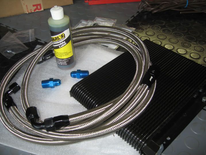
Cooler kit could have been cheaper with rubber hoses and non-thermo plate, but I wanted the reliability of steel mesh wrapped and the added benefit of oil coming to operating-temperature quicker with the thermo-valve, so it was about $100 more than rubber and $50more for thermo-plate. Parts used were: in-case anybody is looking to do the same
PARTS LIST
Tru-Cool Oil cooler -TRU-M7B---$65-(plate/fin style-"supposedly" used by NASCAR/Lemans teams-but cannot confirm)
Mocal Thermostatic sandwich plate 20MM -MOC-SP1FT----$87
Mocal 1/2" BSP x -8AN fitting -MOC-2BM808A---$16
x2 Summit BPT to 8AN adapter fittings- SUM-220847---$10
10 ft summit 8AN hose - SUM-230810---$45 (15 feet if you are not good at cutting stainless hose)
x2 Summit 8AN 90' hose ends -SUM-220887B---$30 (on the thermo/block side-can use straights if you delete black box. I did not)
x2 Summit 8AN straight hose ends-SUM-220890B----$14
Total = $267 + tax/shipping so figure $300.
You can do it for much less if you don't go AN style or thermostatic plate-- BUT this is your engine's life blood so the splurge was well worth the protection.
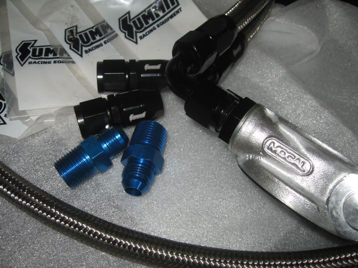
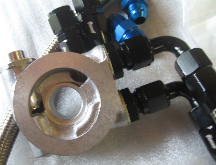
Hoses cut + assembled with lube, ready for install. Blue fittings go into the cooler.
I started with mounting the cooler into position first. I chose the passenger side of the car since it will not interrupt air flow to the header. I did some research and found this to be the recommended orientation to install and allow proper oil flow with little to no oil pressure drop(cannot confirm). Oil comes in the bottom, and flows back through the top. This allows it to cool AND force out any air in the system. Dad fabbed up a bracket out of another metal shelf bracket(see throttle cable bracket^)
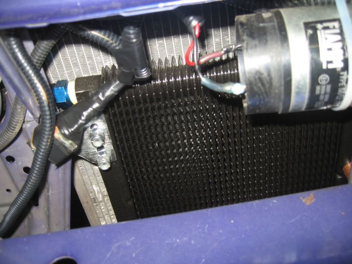
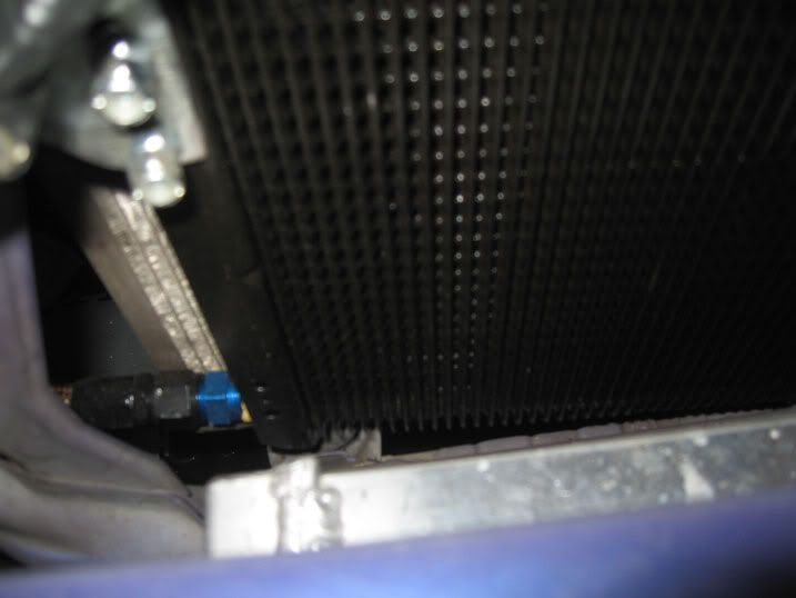
The cooler is mounted between the FMHE (front mount heat exchanger) and the radiator and there is a lot of room to go with a wider cooler if needed (2.5'-3"). This one is rated at 20,500 BTU so it should be plenty for my mildly boosted setup. Also take notice not to kink the hoses or install near any potential sharp metal bits or things that could rub or poke holes.
This is the inside of the thermostatic sandwich plate, a pretty nifty idea. The thermostat reduces the oil going into the oil-cooler until the engine reaches a set temperature. I think this is rated at 180F, tested it in the pot of boiling water and it does work...I think the split is like 15/85 (15% flow to cooler before thermo opens)
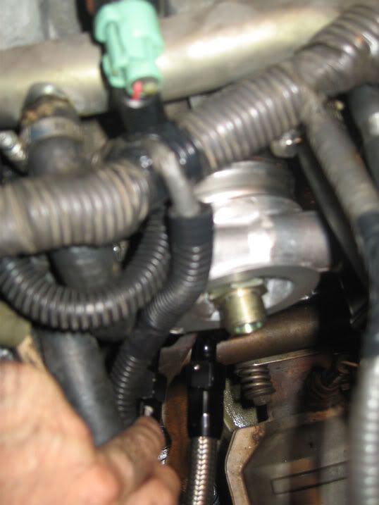
As you can see the plate is then "sandwiched" on between the block(or OEM oil cooler in my case) and the oil filter. Tested and no leaks so far, after warming up the engine to seal gaskets.
I needed the 90's, with the JRSC and the black box still installed there is no other option. BUT if you have the room you could use straights coming off the plate.
Then connect the hoses and that should be it. You can see mine running under the intake to the cooler.
I don't have any statistical data on the before and after temps, but I can tell you that the car warms up as normal and stays at about 1 tick left of center, and really doesn't move much, despite repeated bouts of acceleration/deceleration. I will have to get the data-logging set up for a track day and get some numbers but thats next year. IN the meantime I'm going to enjoy driving my now more reliable boosted little 4 banger.
A BIG thanks to Mr. Grim who has helped each step of the way from all the way around the globe.
Cooler kit could have been cheaper with rubber hoses and non-thermo plate, but I wanted the reliability of steel mesh wrapped and the added benefit of oil coming to operating-temperature quicker with the thermo-valve, so it was about $100 more than rubber and $50more for thermo-plate. Parts used were: in-case anybody is looking to do the same
PARTS LIST
Tru-Cool Oil cooler -TRU-M7B---$65-(plate/fin style-"supposedly" used by NASCAR/Lemans teams-but cannot confirm)
Mocal Thermostatic sandwich plate 20MM -MOC-SP1FT----$87
Mocal 1/2" BSP x -8AN fitting -MOC-2BM808A---$16
x2 Summit BPT to 8AN adapter fittings- SUM-220847---$10
10 ft summit 8AN hose - SUM-230810---$45 (15 feet if you are not good at cutting stainless hose)
x2 Summit 8AN 90' hose ends -SUM-220887B---$30 (on the thermo/block side-can use straights if you delete black box. I did not)
x2 Summit 8AN straight hose ends-SUM-220890B----$14
Total = $267 + tax/shipping so figure $300.
You can do it for much less if you don't go AN style or thermostatic plate-- BUT this is your engine's life blood so the splurge was well worth the protection.
Hoses cut + assembled with lube, ready for install. Blue fittings go into the cooler.
I started with mounting the cooler into position first. I chose the passenger side of the car since it will not interrupt air flow to the header. I did some research and found this to be the recommended orientation to install and allow proper oil flow with little to no oil pressure drop(cannot confirm). Oil comes in the bottom, and flows back through the top. This allows it to cool AND force out any air in the system. Dad fabbed up a bracket out of another metal shelf bracket(see throttle cable bracket^)
The cooler is mounted between the FMHE (front mount heat exchanger) and the radiator and there is a lot of room to go with a wider cooler if needed (2.5'-3"). This one is rated at 20,500 BTU so it should be plenty for my mildly boosted setup. Also take notice not to kink the hoses or install near any potential sharp metal bits or things that could rub or poke holes.
This is the inside of the thermostatic sandwich plate, a pretty nifty idea. The thermostat reduces the oil going into the oil-cooler until the engine reaches a set temperature. I think this is rated at 180F, tested it in the pot of boiling water and it does work...I think the split is like 15/85 (15% flow to cooler before thermo opens)
As you can see the plate is then "sandwiched" on between the block(or OEM oil cooler in my case) and the oil filter. Tested and no leaks so far, after warming up the engine to seal gaskets.
I needed the 90's, with the JRSC and the black box still installed there is no other option. BUT if you have the room you could use straights coming off the plate.
Then connect the hoses and that should be it. You can see mine running under the intake to the cooler.
I don't have any statistical data on the before and after temps, but I can tell you that the car warms up as normal and stays at about 1 tick left of center, and really doesn't move much, despite repeated bouts of acceleration/deceleration. I will have to get the data-logging set up for a track day and get some numbers but thats next year. IN the meantime I'm going to enjoy driving my now more reliable boosted little 4 banger.
A BIG thanks to Mr. Grim who has helped each step of the way from all the way around the globe.
09-25-2012, 12:00 PM
#57
R.I.P. Mark
iTrader: (1)
Join Date: Jan 2008
Location: Melbourne, Australia
Posts: 1,377
Likes: 0
Received 2 Likes
on
2 Posts
""A BIG thanks to Mr. Grim who has helped each step of the way from all the way around the globe. ""
more than Happy to help
only suggestions I have now or food for thought would be
remote oil filter as there a pain under the SC
cold air intake "you know why"
lower temp fan switch and thermostate "will compensate for oil cooler infront of rad"
are both fans wired together ?
and stop wearing those sexy shoes thats a 10kw unfair advantage LOLz
10-14-2012, 02:40 PM
#58
Honda-Tech Member

Join Date: Jul 2010
Posts: 8
Likes: 0
Received 0 Likes
on
0 Posts
10-15-2012, 05:01 AM
#59
Honda-Tech Member
Thread Starter
Join Date: Sep 2004
Location: far EAST SIDE, NY, USA
Posts: 307
Received 0 Likes
on
0 Posts
Pop that off, try cleaning it. If you have an OHM meter test the two point on the valve, should be between 8-15ohms. I skipped this as I knew it was the problem after the idle would return to normal after tapping the valve with a wrench. The plunger inside was getting stuck and causing to idle erratically. If you have an OBD1 car clean your FITV (fast idle thermo valve-i think) also around the throttle body area. Also check for vacuum leaks.
If you did NOT have an idle issue before, and recently installed the supercharger, I would think its a vacuum leak. BUT if it was always an issue (like me) then check throttle body doesnt bind anywhere, clean out your IACV and FITV, reset ECU and cross your fingers.
Good luck!
 03-10-2013, 07:16 AM
#62
Honda-Tech Member
Thread Starter
Join Date: Sep 2004
Location: far EAST SIDE, NY, USA
Posts: 307
Received 0 Likes
on
0 Posts
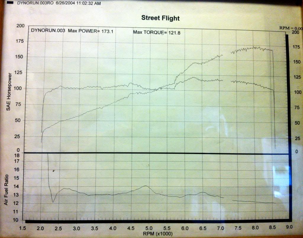
found an old dyno chart from before the JRSC install. Guess this would be my baseline:
JDM B18C, w/ AEM intake, DC 4-2-1 Header, Thermal R&D 2.75" cat-back exhaust.
I also received some Christmas goodies from my brother-in-law (who is a gear head and has no problem exchanging auto parts! got him some stuff for the cutlass)pics to follow. Ordering the catch can setup so will have that up in a bit too
 03-12-2013, 08:28 PM
#64
Honda-Tech Member

Join Date: Aug 2012
Location: San Diego, CA
Posts: 131
Likes: 0
Received 0 Likes
on
0 Posts
Are you having evaporation issues with the reservoir system for your intercooler system? I just finished my lht setup and have been losing about a half gallon per tank of gas (180miles per tank). I'm using pure distilled water, no antifreeze and re-purposed the wiper reservior? No external leaks, hondabond on bolts for purge valve. Top's of pistons look normal (doesn't seem to be internal leak).
BTW, great build. It has helped me along the way.
BTW, great build. It has helped me along the way.
Last edited by hondalocal; 03-12-2013 at 08:32 PM. Reason: update
03-14-2013, 05:06 AM
#65
Honda-Tech Member
Thread Starter
Join Date: Sep 2004
Location: far EAST SIDE, NY, USA
Posts: 307
Received 0 Likes
on
0 Posts
Are you having evaporation issues with the reservoir system for your intercooler system? I just finished my lht setup and have been losing about a half gallon per tank of gas (180miles per tank). I'm using pure distilled water, no antifreeze and re-purposed the wiper reservior? No external leaks, hondabond on bolts for purge valve. Top's of pistons look normal (doesn't seem to be internal leak).
BTW, great build. It has helped me along the way.
BTW, great build. It has helped me along the way.
Water wetter (15%) - Distilled Water (60%) - Anti-Freeze MIX (25%) was obviously too much water not enough antifreeze. DID not pass the freezer test:
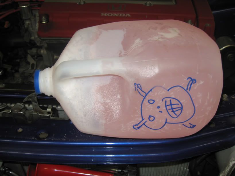
I do know I have a crack in the top of my reservoir cover and so now Im actually concerned about the evaporation. Have you checked for any condensation on the pump or hoses, leaks at every connection etc? I used permetex on most of the connections, not crazy about that stuff but if it works and doesn't screw my internals than its worth it.
03-14-2013, 09:44 AM
#67
Honda-Tech Member
Thread Starter
Join Date: Sep 2004
Location: far EAST SIDE, NY, USA
Posts: 307
Received 0 Likes
on
0 Posts
 03-14-2013, 02:27 PM
#69
Honda-Tech Member
Dude, with the air to water cooler I'd be pushing 12psi!
Get it done!
I wanna see 300whp out of you with a flat FLAT tq curve!
03-15-2013, 03:08 PM
#70
Honda-Tech Member
Join Date: Aug 2012
Location: San Diego, CA
Posts: 131
Likes: 0
Received 0 Likes
on
0 Posts
I called LHT, they said the open loop system w/reservior would likely evaporate a fair amount of water. They usually run a closed loop system to prevent such evaporation. I might try adding some water wetter to see if that has any effect on slowing the evaporation. Or just carry an extra gallon of DI water in the trunk. Lol.
03-15-2013, 03:13 PM
#71
Honda-Tech Member
Join Date: Aug 2012
Location: San Diego, CA
Posts: 131
Likes: 0
Received 0 Likes
on
0 Posts
Enjoy it for what it is now, but if you do the crv pully and mvm stepper, it will be a whole new car. That's what i'm running and I swear I see boost touch 14 psi at full throttle. I get a fair amount of slippage at high rpm's though. Guess it's time to tighten belts again. I'll be posting my write-up w/pics soon!
03-17-2013, 06:23 AM
#72
Honda-Tech Member
Thread Starter
Join Date: Sep 2004
Location: far EAST SIDE, NY, USA
Posts: 307
Received 0 Likes
on
0 Posts
Enjoy it for what it is now, but if you do the crv pully and mvm stepper, it will be a whole new car. That's what i'm running and I swear I see boost touch 14 psi at full throttle. I get a fair amount of slippage at high rpm's though. Guess it's time to tighten belts again. I'll be posting my write-up w/pics soon!
Looking forward to seeing your setup!
03-17-2013, 07:42 AM
#73
Honda-Tech Member
Thread Starter
Join Date: Sep 2004
Location: far EAST SIDE, NY, USA
Posts: 307
Received 0 Likes
on
0 Posts
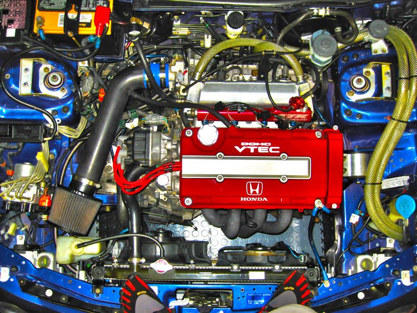
Slight update 3.17.2013 --- VALVE COVER VENTING: (writeup?)
Since longevity and reliability are paramount to power with my build, you will see I already did an after-cooler/heat exchanger, as well as an oil cooler for the SC engine. I see how all of the higher boosted hondas had issues with pressure at the head, so the answer looked to be an aftermarket valve cover venting, routed to a catch can. This is how I went about doing it:
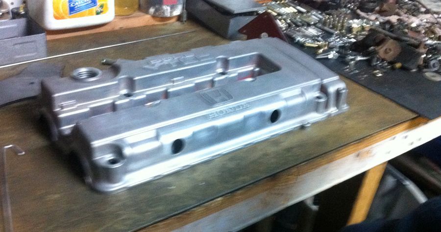
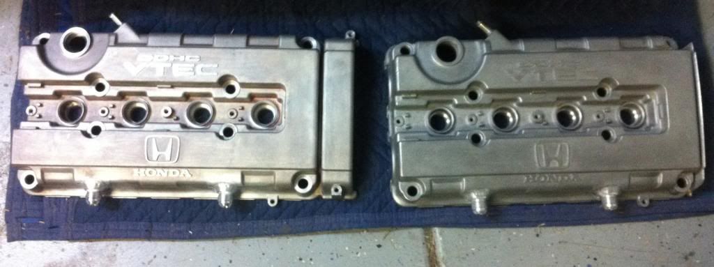
STEP 1: Remove valve cover and all associated hardware (gaskets, nuts, etc) then clean it up real good, because its going in my Dads carry on luggage and going to AZ so my brother can weld in some bungs.
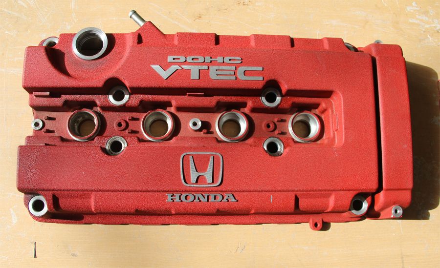
**1 minty fresh but used JDM DOHC VTEC VALVE COVER ready for sacrilege:
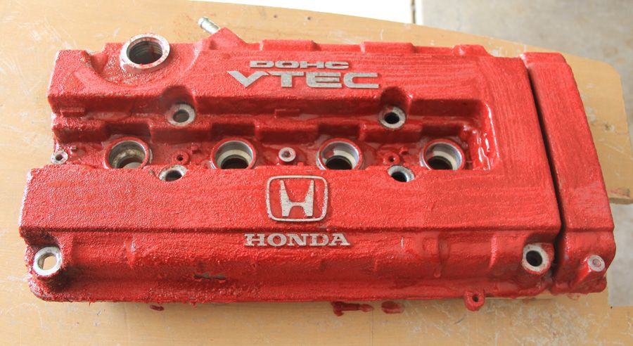
STEP 2: unpack from luggage, place in area that will contain the mess you are about to make. So since we are going to weld on new bungs, all paint and contaminents will have to be removed. For this I used an Aircraft Epoxy Remover. It made things easy, and was quick and simple. NOTE-this was a factory painted VC, so the remover did all the work. I had a spare VC leftover from last year that was supposed to take the place of this one, but the owner had sawed off the timing gear section, and I didnt realize until I got it, so this effectively became the practice valve cover. THis one was coated with some type of baked on paint, and it took 5 times longer, and more work to remove the paint, SO if you are going to do this, start with an OEM VC or one thats already stripped.
**(RED)VC coated with epoxy remover, starting to bubble, this stuff came off with almost no work at all. You can see it lift from the aluminum in about 2 minutes.
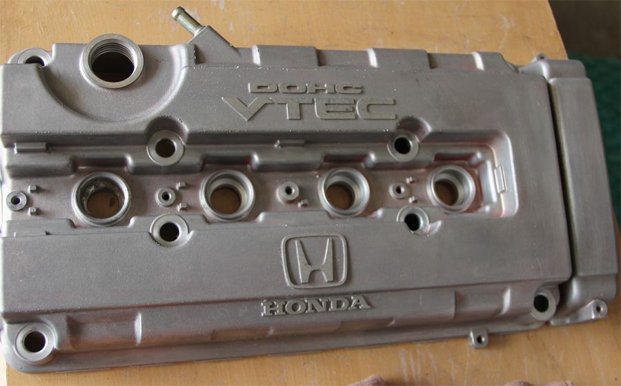
STEP 3 -- remove remover/old paint with a hose/rag/wire-brush/scotch-brite pad combo, this step depends on what paint you had. Since the VC are aluminum, and that is a pourus metal, it actually soaks up some of the oil that it contains. OIL + WELDING = contamination and thats the last thing you want, so clean the hell out of it. I used laquer thinner on the inside, and one last coat of epoxy remover on top. Then "it gets the hose again" -WildBill, "Silence of the Lambs"
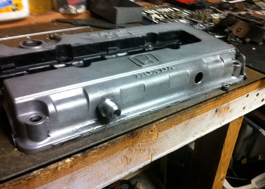
**ALL CLEAN, ready for drilling/welding,etc - take note of all flaws in the casting above the DOHC area, you can address this now, but I save it for later when cosmetics are the focus.
STEP 4 -- Prepare to drill holes, then drill. You cant be too careful or accurate here, so measure twice, for center of VC, use a punch on dead center, then start with a small bit and work your way up until you can just barely fit your fittings into VC. *Be careful not to drill past the cover and into the oil baffle. You can do this by wrapping your bit in masking tape about 1/2' past the tip. Use that as you stop drilling now guide. I used a hole saw on the first VC. It was NOT a good idea, as I drilled too big, and made it more difficult to weld. Welding aluminum is a whole lot different from welding steel. My brother was nervous so thats why I sourced x2 more fittings for testing, incase the tig was acting up or his settings weren't on point, he could work it out on the (BLACK) VC, and then apply that to the (RED) VC, for a perfect weld. AGAIN I cannot stress enough how important it is to have a clean metal to start with. Think its clean enough? Clean it 1 more time. Contamination sucks and ruins things. Anyways...
**here is VC (red), with holes drilled too big. If you dont have a bit large enough, borrow one, or buy one, or have someone else do it. DONT make the mistake of using the smalles hole saw you have (which is still too big) and then rely on your brothers welding ability to get it positioned correctly, with not much aluminum near it to weld to, ie lots of filler rod.
**here is the (BLACK) VC after 6-7 coats and scrapings, the paint was so tough. Anyways, holes are drilled, fittings are snug, ready for welding. This VC officially became the test dummy.
STEP 5 -- FEED PACMAN or WELD in bungs
I can weld steel decently, in my opinion. However to someone who knows what they are doing, well Im sure they could tell me its wrong, horrible, ugly, bad pooling etc. I know practice makes perfect, but not on my VC, so hand over project to brother in law who is a mechanical engineer and use to work at Roush and Paul Yaffy Customs buildings bikes, and watch him work. I would take your VC to a professional at this point if you dont have a family member or friend who knows how to weld-ALUMINUM, well. ITs a lot of work to just get a puddle going, never mind make it look good and be solid.
***feeding PACMAN
STEP 6 - rejoice! sit back, crack a beer, and just be happy the valve cover didnt warp and it all worked out well.
**VC BLACK - ready for more paint stripping
**BOTH VC's clean and ready for powder coating.
(more pics coming from the Powder coater)
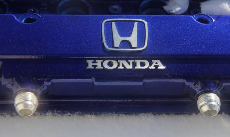
*Note, I used both earls, (hexed fitting) and B&R fittings(rounded) for the valve cover. I like the look of the round fittings better, not sure that the hex head did anything, but I can tell you they cost more... Both are sized 10AN which I determined was a good middle ground for this build. I will be ordering this catch can kit from B&R as I priced out a similar setup using a moroso catch can, 10an fittings,etc from SUMMIT, and the price is actually less from B&R. Intall on that to come in a month or so weather pending.
Since longevity and reliability are paramount to power with my build, you will see I already did an after-cooler/heat exchanger, as well as an oil cooler for the SC engine. I see how all of the higher boosted hondas had issues with pressure at the head, so the answer looked to be an aftermarket valve cover venting, routed to a catch can. This is how I went about doing it:
STEP 1: Remove valve cover and all associated hardware (gaskets, nuts, etc) then clean it up real good, because its going in my Dads carry on luggage and going to AZ so my brother can weld in some bungs.
**1 minty fresh but used JDM DOHC VTEC VALVE COVER ready for sacrilege:
STEP 2: unpack from luggage, place in area that will contain the mess you are about to make. So since we are going to weld on new bungs, all paint and contaminents will have to be removed. For this I used an Aircraft Epoxy Remover. It made things easy, and was quick and simple. NOTE-this was a factory painted VC, so the remover did all the work. I had a spare VC leftover from last year that was supposed to take the place of this one, but the owner had sawed off the timing gear section, and I didnt realize until I got it, so this effectively became the practice valve cover. THis one was coated with some type of baked on paint, and it took 5 times longer, and more work to remove the paint, SO if you are going to do this, start with an OEM VC or one thats already stripped.
**(RED)VC coated with epoxy remover, starting to bubble, this stuff came off with almost no work at all. You can see it lift from the aluminum in about 2 minutes.
STEP 3 -- remove remover/old paint with a hose/rag/wire-brush/scotch-brite pad combo, this step depends on what paint you had. Since the VC are aluminum, and that is a pourus metal, it actually soaks up some of the oil that it contains. OIL + WELDING = contamination and thats the last thing you want, so clean the hell out of it. I used laquer thinner on the inside, and one last coat of epoxy remover on top. Then "it gets the hose again" -WildBill, "Silence of the Lambs"
**ALL CLEAN, ready for drilling/welding,etc - take note of all flaws in the casting above the DOHC area, you can address this now, but I save it for later when cosmetics are the focus.
STEP 4 -- Prepare to drill holes, then drill. You cant be too careful or accurate here, so measure twice, for center of VC, use a punch on dead center, then start with a small bit and work your way up until you can just barely fit your fittings into VC. *Be careful not to drill past the cover and into the oil baffle. You can do this by wrapping your bit in masking tape about 1/2' past the tip. Use that as you stop drilling now guide. I used a hole saw on the first VC. It was NOT a good idea, as I drilled too big, and made it more difficult to weld. Welding aluminum is a whole lot different from welding steel. My brother was nervous so thats why I sourced x2 more fittings for testing, incase the tig was acting up or his settings weren't on point, he could work it out on the (BLACK) VC, and then apply that to the (RED) VC, for a perfect weld. AGAIN I cannot stress enough how important it is to have a clean metal to start with. Think its clean enough? Clean it 1 more time. Contamination sucks and ruins things. Anyways...
**here is VC (red), with holes drilled too big. If you dont have a bit large enough, borrow one, or buy one, or have someone else do it. DONT make the mistake of using the smalles hole saw you have (which is still too big) and then rely on your brothers welding ability to get it positioned correctly, with not much aluminum near it to weld to, ie lots of filler rod.
**here is the (BLACK) VC after 6-7 coats and scrapings, the paint was so tough. Anyways, holes are drilled, fittings are snug, ready for welding. This VC officially became the test dummy.
STEP 5 -- FEED PACMAN or WELD in bungs
I can weld steel decently, in my opinion. However to someone who knows what they are doing, well Im sure they could tell me its wrong, horrible, ugly, bad pooling etc. I know practice makes perfect, but not on my VC, so hand over project to brother in law who is a mechanical engineer and use to work at Roush and Paul Yaffy Customs buildings bikes, and watch him work. I would take your VC to a professional at this point if you dont have a family member or friend who knows how to weld-ALUMINUM, well. ITs a lot of work to just get a puddle going, never mind make it look good and be solid.
***feeding PACMAN
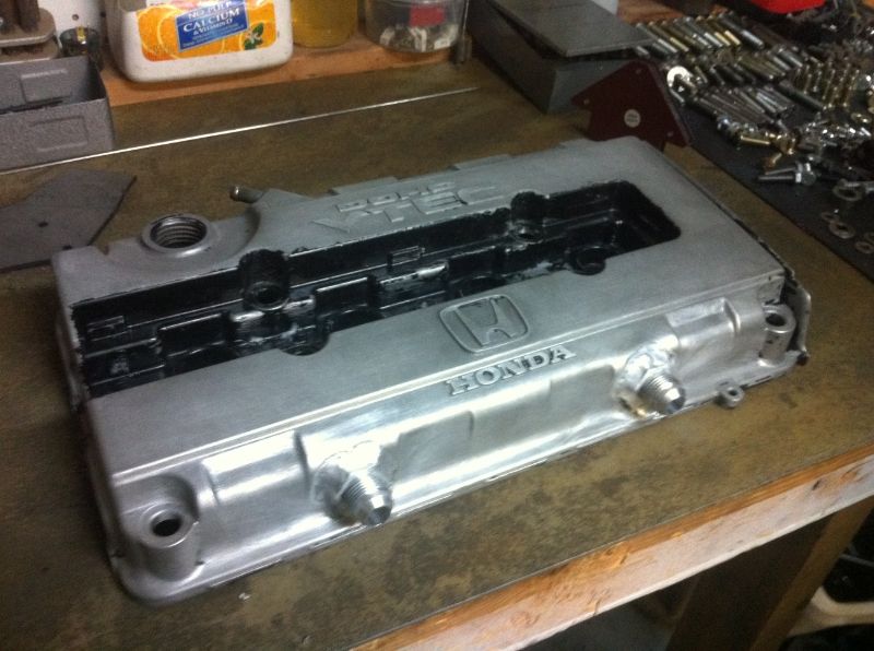
STEP 6 - rejoice! sit back, crack a beer, and just be happy the valve cover didnt warp and it all worked out well.
**VC BLACK - ready for more paint stripping
**BOTH VC's clean and ready for powder coating.
(more pics coming from the Powder coater)
*Note, I used both earls, (hexed fitting) and B&R fittings(rounded) for the valve cover. I like the look of the round fittings better, not sure that the hex head did anything, but I can tell you they cost more... Both are sized 10AN which I determined was a good middle ground for this build. I will be ordering this catch can kit from B&R as I priced out a similar setup using a moroso catch can, 10an fittings,etc from SUMMIT, and the price is actually less from B&R. Intall on that to come in a month or so weather pending.
06-07-2013, 05:52 PM
#75
Honda-Tech Member
Thread Starter
Join Date: Sep 2004
Location: far EAST SIDE, NY, USA
Posts: 307
Received 0 Likes
on
0 Posts
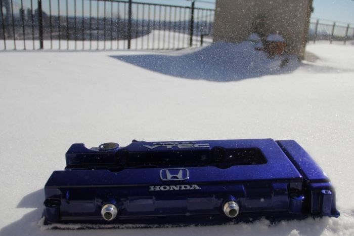
quick update. Got the valve cover powder-coated and got the car to pass inspection (I failed because my license plate lights were out--I had inadvertently ripped the connection out when removing the rear bumper to adjust something and had no idea they were out until inspection day)
Anyway after driving on the highway for 100 miles with no problems I hit traffic as I neared my destination. The car started to run hot, about halfway on temp. gauge and triggered my check engine light/protection mode from the Hondata( set at 220f). So now I have to figure out how to bring engine temps down for the track if just some mild traffic is resulting in a limp mode. I dont want to get on track only to find out I can run only two laps.
So now how do I cool this thing down? Is the next logical step a larger radiator (dual core) like a Fluidyne or Koyo? I was also thinking of a Mishimoto triple core civic radiator (half tank) so I could squeeze a PLM header in there. Anyone have any thoughts on the integra vs civic radiators? I feel like I see a lot of boosted integras with the half radiator.