
Tranny Overhaul & JDM ITR Final Drive/LSD Install (56k...not so much)
 03-11-2004, 05:56 AM
#1
Honda-Tech Member
Thread Starter
iTrader: (3)
Join Date: Jan 2000
Location: Bloomington, IN, USA
Posts: 10,180
Likes: 0
Received 3 Likes
on
3 Posts
Tool List:
__________________________________________________ _________________________________
1.) Helm 1994, 1995, 1996, or 1998 Integra Service Manual
2.) 3/8" drive Deep Socket set
3.) 3/8" Ratchet (optional 3/8" Speed Wrench, or 3/8" Pneumatic Impact Wrench)
4.) 1/2" drive Ratchet
- Sears Craftsman 44809 ($22.99) [Pic]
5.) 3/8" drive Torque Wrench (10lb*ft minimum, 100lb*ft maximum)
- Matco Tools TRB100 ($228.30) [Pic]
6.) 27mm 1/2" drive Deep Socket [Pic]
7.) 32mm 1/2" drive Deep Socket
8.) 1/2" drive Impact Wrench
- Ingersoll-Rand 2135Ti ($259.99) [Pic]
9.) 3/8" drive Impact Wrench
- Ingersoll-Rand 2115Ti ($219.99)
10.) Snap Ring Pliers [Pic]
- Mac Tools PK4Q ($59.99)
11.) Retaining Ring Pliers
- Mac Tools P35 ($55.11)
- Sears Craftsman ($19.99)
12.) 6" or larger Bench Clamp [Pic]
13.) (2) 2'x4' pieces of wood (approx. 1ft in length)
14.) Feeler Gauges (.0015" minimum thickness, .002", .003", .004" req'd)
- Sears Craftsman 40804 ($5.99) [Pic]
15.) 17" Pry bar
- Sears Craftsman 43276 ($14.99)
16.) Dead Blow Hammer [Pic]
17.) 2lb Sledge Hammer or equivalent [Pic]
- Mac Tools CH32DDS-O ($81.11) [Pic]
18.) Rolled Punch Pin Set
- Sears Craftsman 43167 ($19.99) [Pic 1] [Pic 2]
19.) Seal Driver Set [optional] [Pic]
- you can use sockets and extensions instead to drive new seals/bearings in or drive stuff out
20.) Bushing Driver Set [optional] [Pic]
21.) 9" 3/8" drive Extension
22.) 1 5/8" or 1 11/16" Socket
- Sears Craftsman 47783 or 47784 ($19.99)
23.) 1/2" to 4 5/8" Bearing Splitter [Pic]
- OTC 1122, toolsource.com ($51.95)
24.) 1/8" to 2" Bearing Splitter [optional]
- OTC 1123, toolsource.com ($37.95)
25.) 7 ton Adj 2-Jaw Puller
- Sears Craftsman 46903 ($29.99)
26.) 14mm Box Wrench [Pic]
27.) 6" length of 1.5" PVC Pipe - [Pic]
- Bloomington Hardware ($.50/ft)
29.) Parts Washer
30.) Work Bench (minimum of 2ft x 2ft)
Supplies Needed:
__________________________________________________ _________________________________
1.) Brake Parts Cleaner
- Walmart ($1.69) [Pic]
2.) Palmolive Dish Soap, Dish Brush, Pipe Brushes for cleaning
3.) Whipped Cream Bucket [Pic]
- for holding MTF to dip parts into before assembly
4.) Razor Blades for removing old silicone gasket sealant
5.) Scotch-Brite Pads - removing old silicone gasket sealant and cleaning mating surfaces of casings
6.) Lacquer Thinner -removing old silicone gasket sealant and cleaning mating surfaces of casings
Applicable OEM Honda Tools:
__________________________________________________ _________________________________
Slide Hammer (3/8"x16)
-
07736-A01000A : Adjustable Bearing Puller (25mm to 40mm) [Pic]
- Baranco Acura ($72.20)
07GAJ-PG20130 : Mainshaft Base
- Stephens Honda ($19.42)
07GAJ-PG20110 : Mainshaft Holder
- Stephens Honda ($90.xx)
07749-0010000 : Seal Driver Handle
- Stephens Honda ($16.61)
07947-SD90200 : Seal Driver Attachment (Gear Housing)
- Stephens Honda ($30.26)
07JAD-PH80101 : Seal Driver Attachment (Clutch Housing)
- Stephens Honda ($29.45)
Parts List:
__________________________________________________ _________________________________
Part numbers for everything that comes with the JDM ITR Final Drive kit (courtesy of hondaswap.com):
41233-P80-E30 : 4.785 DIFERENTIAL RING GEAR
23421-P80-E30 : COUNTERSHAFT FIRST GEAR
91107-P80-E30 : FIRST GEAR NEEDLE BEARING (x2)
23914-P80-E30 : COLLAR RING
23221-P80-E30 : 4.785 COUNTERSHAFT
Parts numbers for Differential:
41200-P80-003 : ITR LSD
91005-P80-E31 : Differential ball bearings (x2)
41xxx-Pxx-B00 : 80mm Differential shim (for use with the enclosed differential ball bearings [91005-P80-E31])
Required Replacement Parts
90202-PH8-000: Countershaft Lock Nut (23mm) [Pic]
08718-0001: Hondabond HT [Pic]
Honda MTF or MTF-II (x3)
- MTF: 08798-9016 (red cap) [Pic] [since MY2000]
- MTF-II: 08798-9031 (white cap) [Pic] [since MY2007]
Recommended Replacement Parts
91211-P21-008 : 1st Gear (Lower) Friction Dampener
91212-P21-008 : 2nd Gear (Upper) Friction Dampener
91216-PH8-005 : Clutch Housing Mainshaft Oil Seal
91002-PS1-003 : Clutch Housing Mainshaft Bearing (28x60x15)
91101-P80-008 : Clutch Housing Countershaft Needle Bearing (33x60x20)
91205-PL3-A01 : Clutch Housing Axle Seal (35x56x8)
239xx-P21-000 : 72mm Mainshaft thrust shim
23927-PG2-A00 : Mainshaft Spring Washer (28mm)
23928-PS1-000 : Mainshaft Thrust Washer (28mm)
91205-PC9-711 : Gear Housing Axle Seal (40x62x8)
91105-P21-003 : 2nd Gear Needle Bearing
91003-P21-003 : Countershaft Ball Bearing
91102-PLW-003 : Countershaft Roller Bearing (25x52.2x15)
Start Procedure:
__________________________________________________ _________________________________
1.] Opening the Casing
Set the tranny bellhousing on 2'x4's to keep the input shaft from bottoming out.
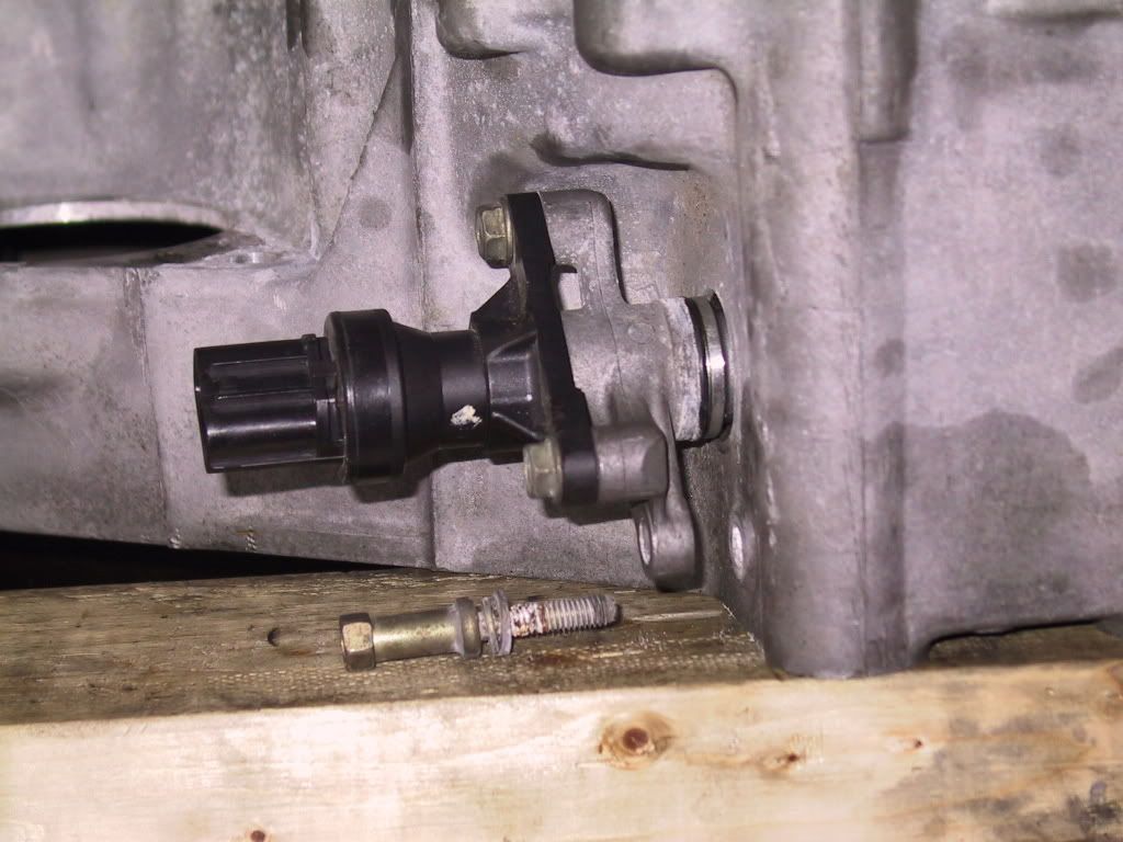
3/8" Ratchet, 10mm Socket: Remove long M6x1.00 bolt. Remove the VSS by twisting/wiggling the VSS a little and pull up.
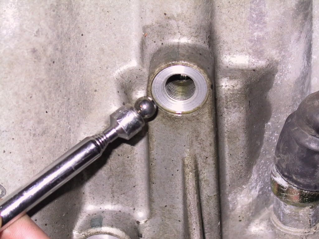
3/8" Ratchet, 12mm Socket, Magnetic Pick Up Tool: Remove the two plugs and 5/16" ball bearings on the bottom of the tranny that stake the 1st/2nd and 3rd/4th shift forks.
3/8" Impact, 12mm Socket: You also need to remove the other tranny hanger (Hanger B) to get to one of the casing bolts.
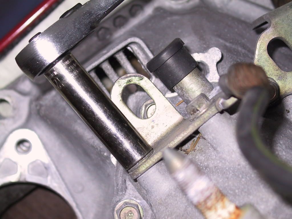
3/8" Impact Wrench, 6" or longer Extension, 12mm Socket: Remove casing bolts per loosening pattern.
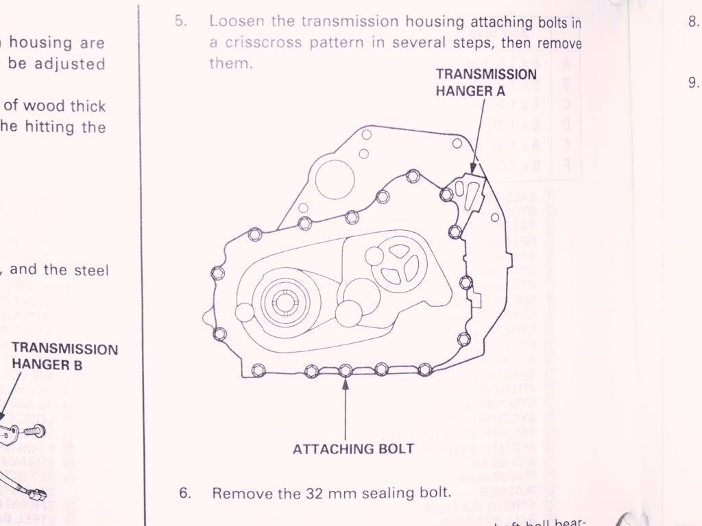
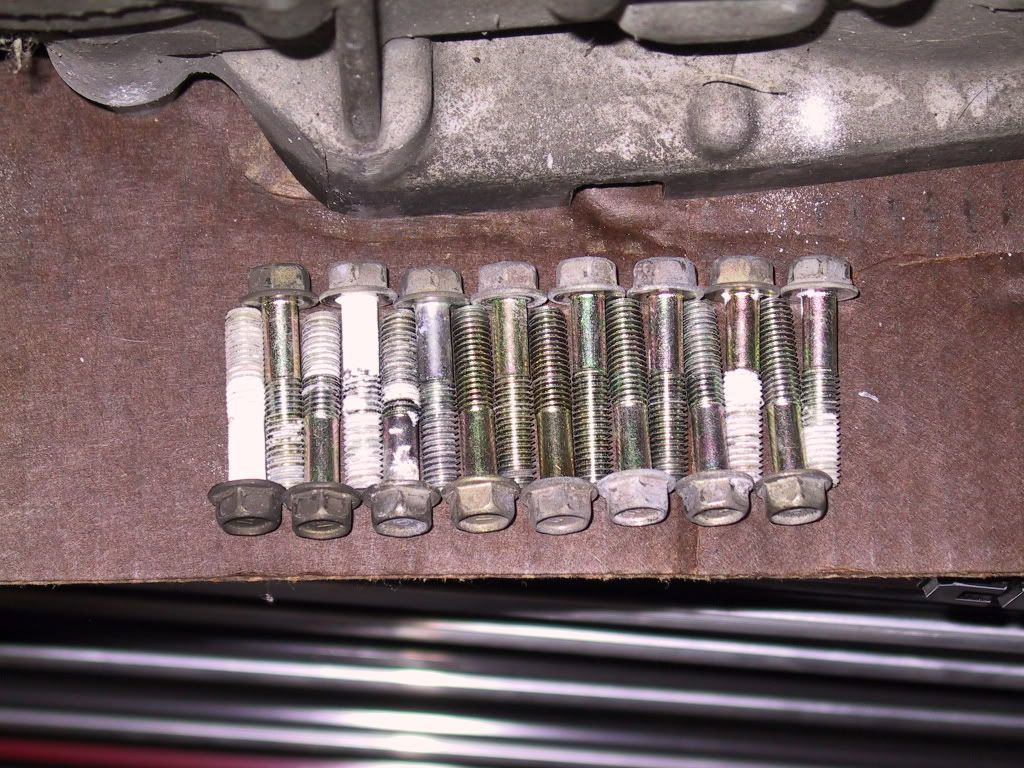
All the bolts are the same length, so you don't need to worry about marking any odd-length bolts to their original locations.
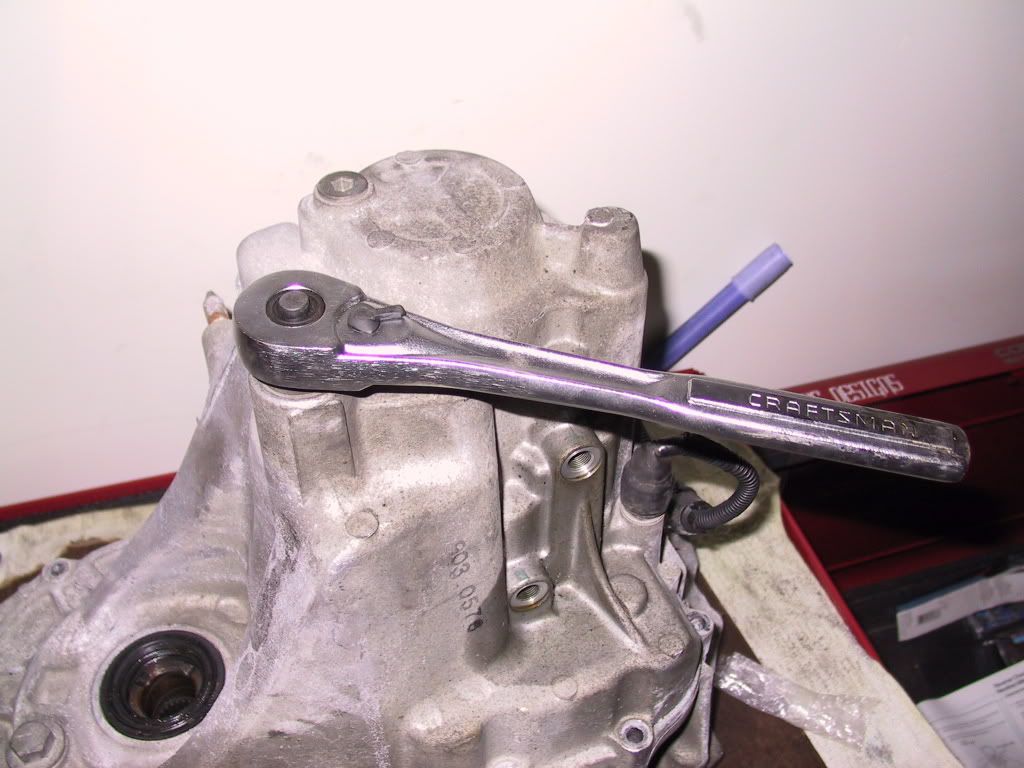
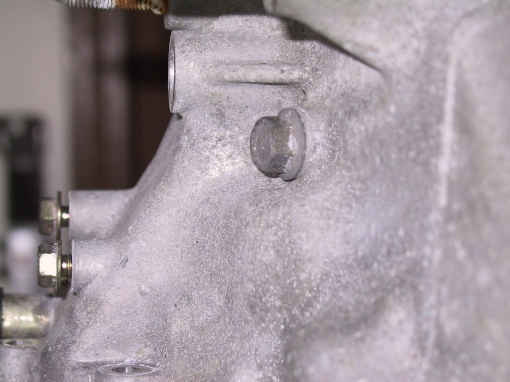
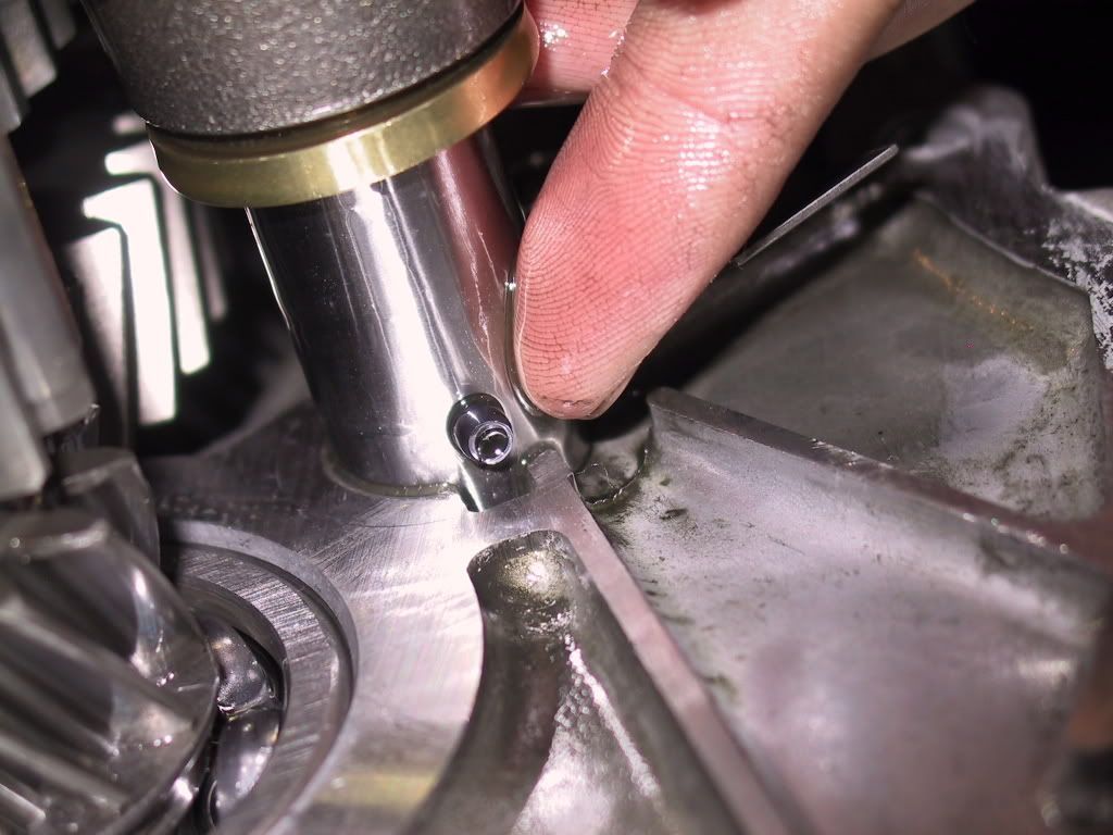
1/2" Ratchet, Hammer: Remove the 32mm sealing bolt
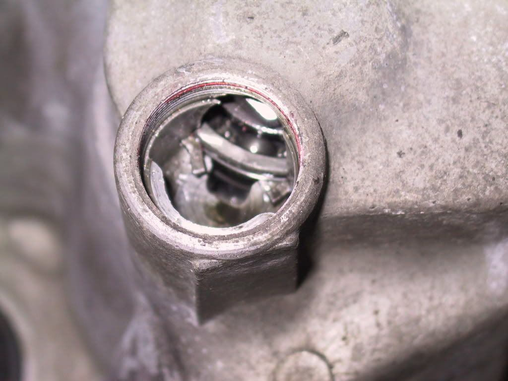
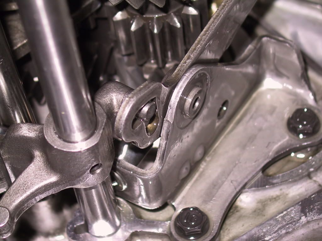
Snap Ring Pliers: This is the snap ring under the 32mm sealing bolt. Expand it with a pair of snap ring pliers. You can spin the ring around to get better positioning on it.
Locked position
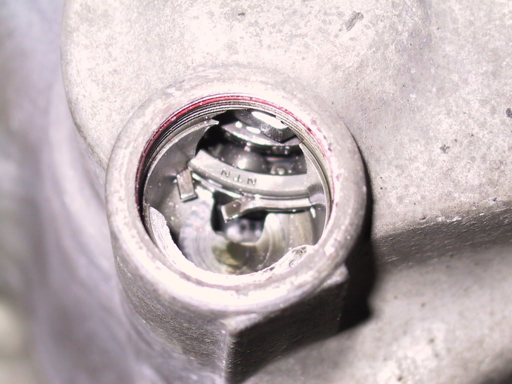
Unlocked position - You'll hear the countershaft drop when you've expanded the snap ring enough.
3/8" Ratchet, 14mm Socket: Remove the reverse idler gear shaft bolt on the top of the tranny casing.
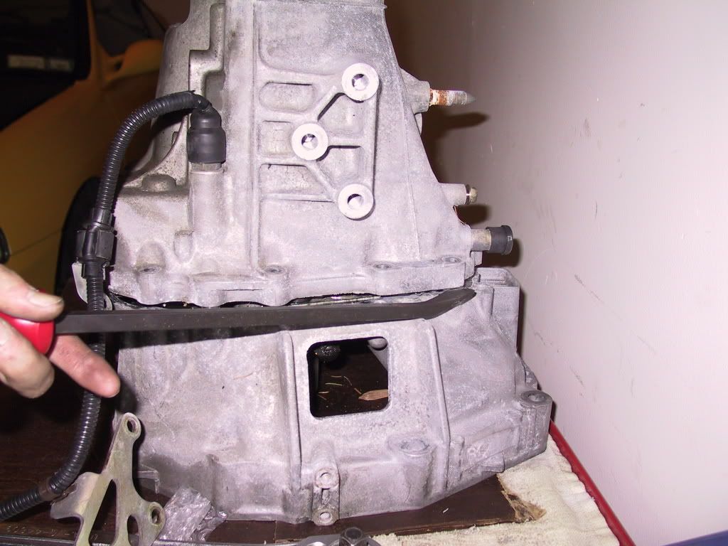
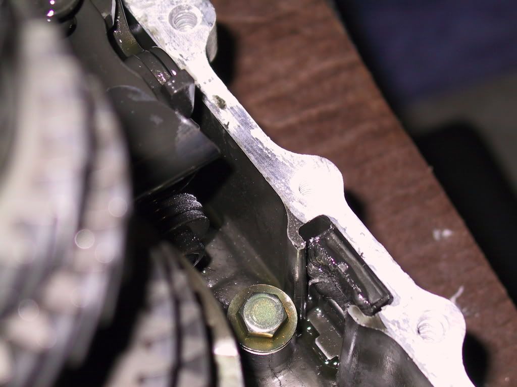
17' Pry Bar: Pry here and the casing will come up and then you can pull it straight up off the bottom of the bellhousing.
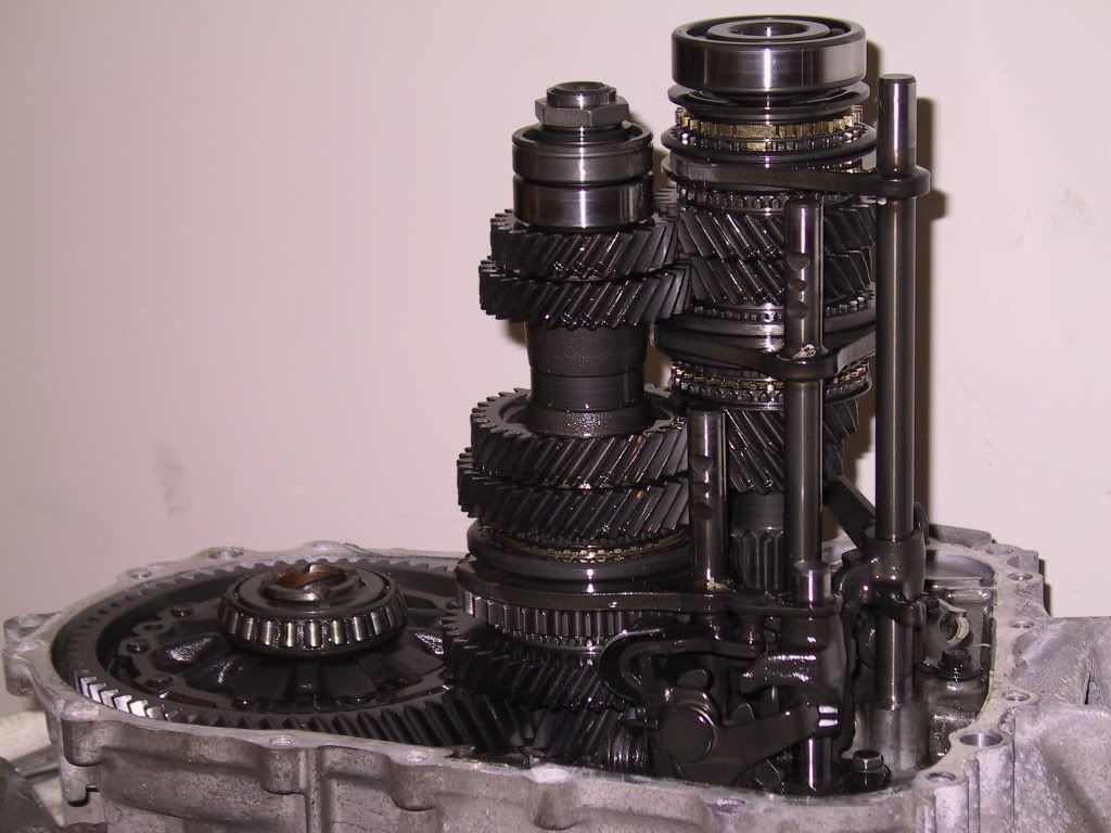
A couple of shots of the gear sets. Differential - countershaft - mainshaft/input shaft (from left to right in both pics).
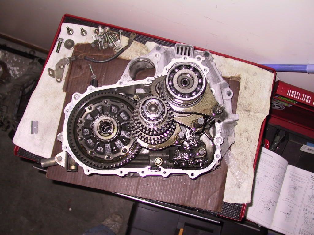
Inside of the gear housing.
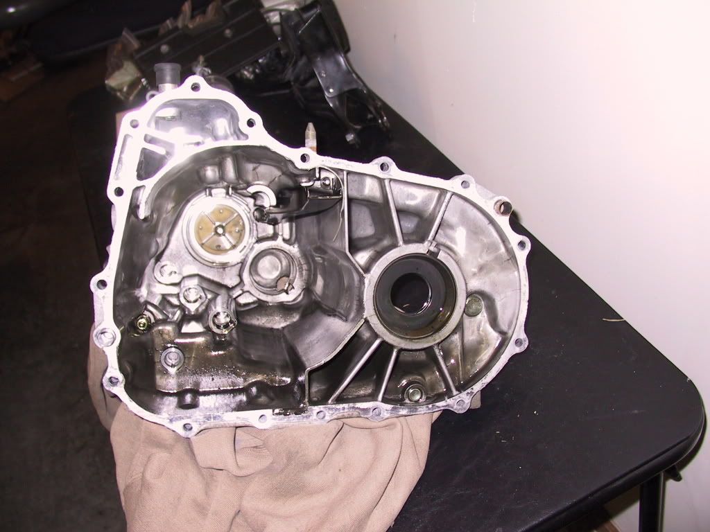
Tranny magnet just below the change holder.
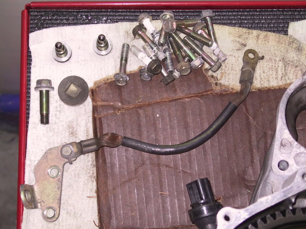
All the hardware that should have come off the tranny to this point.
__________________________________________________ _________________________________
2.] Removing the Gearset & Differential
Reverse change holder needs to be removed by taking out those two 10mm bolts.
Remove the reverse idler gear and shaft by pulling the shaft up and out first, then the gear.
After removing the reverse idler change holder, gear, and shaft.

Checking a few clearances....maybe I'll elaborate later and put in the tolerance ranges.


Remove the change holder assy for the forward gears by taking out three 10mm bolts. Two at the bottom and one on the opposite side of the change holder.


Change holder assy. I put the shaft back in after removing it.

The change holder uses different bolt lengths. One (lighter color) is shorter than the other two (darker).

After removing the change holder assy. Time to remove both the gearsets and shift forks.

The mainshaft, countershaft, and shift forks are removed as a whole unit. Hold the two shafts and three forks together and
pull them upwards with a little finesse to get them to ease out.

These guys hang around after removing the gearsets. Spring washer (it's the concave one) on bottom and washer on top. (As
seen in above diagram.)

Clutch housing after removing the gear sets and shift forks. You can now see the clutch housing counter and main shaft
bearings.

Now remove the differential assy. Pull it straight up to get it out of the clutch housing.

Gear housing side of the differential.

Clutch housing side of the differential.

__________________________________________________ _________________________________
3.] Installing the New FD, LSD, and Differential Ball Bearings
Tapered roller bearings. You won't be using these kind on the LSD. It's recommended that you switch over to the enclosed
differential ball bearings to make it easier to measure the clearance needed b/w the differential and gear housing.

You can see the separate outer race for the tapered roller bearings here in the clutch housing. There is a 2.5mm thick
thrust shim directly underneath the outer race, sandwiched b/w the differential outer race and the axle seal.

The new ones differential bearings are enclosed and no longer use the separate outer race or the thrust shim behind the outer
race in the clutch housing. Front and back view of the enclosed bearings shown here.

Remove the (10) 14mm bolts to separate the final drive gear from the differential: The bolts are reverse-thread, so
it's righty-loosey, lefty-tightey. The only reason I separated the two was to reuse the bolts. If you buy (10) new ones and
are installing a new differential and final drive, you won't have to mess with this part.

New ITR LSD and JDM ITR 4.785:1 final drive ring gear. Courtesy of Jeff (Lip) and Dave/Chad @ R&D Motorsports.

Put the new ring gear onto the differential.

Rotate the ring gear on the differential to get the holes to line up. It shouldn't be fussy and slide around as smooth as
buttah.

Clean the bolts with brake parts cleaner to remove the oil.

Apply threadlocker to the (10) bolts.

I used a 14mm deep socket on a short extension to quickly thread the bolts in. Remember that the bolts are reverse-thread.

Clamp the differential/ring gear assy into a table clamp with two planks of wood. Torque the bolts to 74.5lb*ft. Hopefully
your's is mounted to a table...unlike mine. I really had to fight it to torque the bolts down.

Lube up the differential bearing and differential with MTF. Place the the bearing onto the differential.

I used a a plank of wood to get it as far down as possible and then 1 5/8" socket to knock the bearing all the way down onto
the differential.

Done with that clutch housing side.

Done with the gear housing side.

Something I noticed is that the enclosed bearings don't leave as much differential exposed as the old exposed bearings. I'm
hoping that this it normal and maybe Dan or Willard will confirm this. It makes sense that it would be like that b/c the old
bearings mate with an outer race that's in the tranny casing halves. The new ones don't have that outer race in the casing
halves.

Old exposed differential bearings on gear housing side

New enclosed differential bearings on gear housing side

Before we check the differential-to-housing clearances to determine what new shim thickness we need, we need to remove the
outer races interference press-fit into the housings.
I'm not sure if it's mandatory to remove the axle seals to hammer out the outer races, but since I had replacements already,
I did it anyways. I used a nut driver and hammer to knock the axle seals outwards. They come out really easily, so you
don't need to pound them really hard.
Clutch housing side

One punch and it'll push it out...

...and you can pick it up with your hand.

Gear housing side - removing the axle seal.

Flip the clutch housing over so you can hammer out the outer race on this side.

I used a seal installer to drive it out. A few gentle thwacks and it comes out pretty easily.

The shim (left) and outer race (right) - in order of assembly.

Drive out the outer race on the gear housing.

This side had two shims and then the outer race. Since we switched to the enclosed ball bearings, we will no longer use a
79.5mm shim. Instead, we'll only be using a single 80mm diameter shim on the gear housing and no shims on the clutch housing
side.

This is how the outer race interfaces with the tapered roller bearings.


Put a little MTF on the outside of the ball bearing and gently put the differential assy into the clutch housing. Use one
hand from underneath to support the differential to keep it from banging around when trying to let it drop down into the
hole. It should just gently fall into the hole without any hammering. Altho, the manual has recommended it if you can't get
it to drop it easily.


__________________________________________________ _________________________________
4.] Setting Differential Thrust Clearance
Put the gear housing back on to check the differential-to-casing clearance. Don't use any Hondabond to seal the casing.

Torque the bolts to 20lb*ft. Have another person hold the tranny while you torque them down, or do like I did b/c everybody
else went out to dinner.

Make sure that the differential is seated all the way down into the casing before measuring. You can do this with a driver
and hammer. This will help to ensure that you get an accurate reading.
Check the differential-to-casing clearance.

Specified clearance = 0.0mm-.10mm (0.000"-.004")

Insert feeler gauges here. I used angled feeler gauges to make the measurement easier.

Without an 80mm shim already in the tranny (b/c I didn't have one), I had to stack a couple of feeler gauges together to
measure the clearance. These are the 4 that I narrowed it down to. I paired one of the three on top with the .021" feeler
gauge to go up/down a thousandth.

.021"+.022" = .043" Too loose
.021"+.023" = .044" Slides in with a little drag
.021"+.024" = .045" Slides in with a little more effort
I'm gonna say that it's b/w .044" and .045". Then we do a little math to get the appropriate shim thickness to buy.
.044" - .004" = .040" shim
.045" - .004" = .041" shim
With that calculated shim thickness, we go to the shim table and pick out the shim with the thickness that matches
.040"-.041" the best.
Shim K = .0413"
Using shim K, gives me a clearance of (.045" or .044") - .0413" = .0037" to .0027"....under our .004" target clearance.
I could also use Shim B to tighten up the tolerance by .0020" to get a final clearance of .0017" to .0007". I prefer to be
on the tight side, so in this case, I'd recommend the B shim over the K shim.

When you get the new shim, use a pair of snap ring pliers to insert the shim into the recess. This is the shim K I just got
installed.

Once again, put the gear housing back on, and test the differential thrust clearance.

In my case, I ordered the 80mm K shim (.0413"). What I found out was that it still had .007" of clearance when my
calculations predicted a .0037" clearance.

So, I went back and looked at the chart and picked out another shim, shim L (.0453"). I also picked up a shim C (.0472")
just in case. When I checked the thrust clearance with the C shim, it came out to .004". That whole ordeal was pretty odd,
but it's something you should be aware of and ready to expect. I left it at that and moved on.

__________________________________________________ _________________________________
5.] Disassembling the Countershaft
Lock down the countershaft into the bench clamp. Use the 2'x4's in b/w the countershaft and clamp teeth to keep from marring
the countershaft.

Unstake the countershaft lock nut as best as you can with a screwdriver or punch and hammer.
Use a pneumatic or electric impact gun and a 32mm socket to loosen the countershaft lock nut. It'll shear off any of the
staking away when it busts loose, so you don't need to worry about the staking too much.

Remove the countershaft lock nut and spring washer. It's up to you whether or not you want to replace the spring washer or
not, but it's mandatory to replace the lock nut.

Remove the press-fit countershaft ball bearing. The countershaft ball bearing is what locks into the
retaining clip on the gear housing behind
the 32mm sealing bolt.

Remove the countershaft roller bearing's outer sleeve first before installing the bearing puller.
Remove the press-fit roller bearing with the bearing puller.


Remove the 5th, 4th, 3rd, then remove 2nd gear, 1st-2nd gear synchros, and 1st gear as one. They should all just slide off,
but in the case that they don't, you can use the puller in the same fashion as above to remove the gears.
After removing the gears and synchros, you'll be left with the countershaft, thrust shim, and needle bearings.

Gearset in order of removal from left to right.

You will not be reusing the first gear, first gear needle bearings, countershaft, and countershaft thrust shim anymore. You
can pack that stuff up and sell it along with the differential and final drive ring gear.
Remove the friction damper and synchro hub/ring from the 1st gear. Those two items will be reused on the JDM ITR first gear,
unless you choose to replace them as wear items. Clean them with brake parts cleaner and wipe them off with a clean,
lintless rag before moving onto the next step.
__________________________________________________ _________________________________
6.] Assembling JDM ITR Countershaft
These are the parts that make up the 1st gear assy. From the top left, counter clockwise: JDM ITR needle bearings, JDM ITR
ring collar, 1st gear (lower) friction damper [reused], synchro ring & spring [reused], JDM ITR first gear.

This is how the 1st gear assy pieces together:
The two needle bearings go on the ring collar.

Then the first gear slips over and around the ring collar & needle bearings.

The lower friction damper sits tight in the first gear.

The friction damper has a particular orientation that's dependent on the synchro hub. More on that later.

The synchro ring presses down onto the first gear.

Fully assembled first gear assy.

Now for the actual assembly of the countershaft.

Separate the ring collar & needle bearings and lower friction damper from the first gear assy.
Lube up the countershaft and ring collar first and then install the ring collar on the JDM ITR countershaft. You may need to
twist it a little while pushing down on it to finesse it all the way down. It should slide all the way down to the top of
the FD gear with minimal resistance.

The pair of needle bearing halves sit on the ring collar, and the first gear rides on the needle bearings. You can lube up
and put the needle bearing halves onto the ring collar now or wait until you have the first two gears assembled before
installing the needle bearings.

I find it easier to assemble the first gear, 1-2 synchro, and second gear into one piece before installing it on the
countershaft.
Synchro hub - bottom side shown (this side faces towards the first gear assy

Take the 1st/2nd gear synchro hub, flip it upside, and set the 1st gear (lower) friction damper so that the tabs fall into
the slots on the synchro hub.

Flip the first gear assy upside-down and mate it to the synchro hub so that the alignment tabs on the synchro ring match the
slots on the synchro hub [Pic]. This will properly orient and seat the friction damper into the first gear. You can flip it
back over and lift up the synchro hub and the friction dampener will be stuck into the first gear in the proper orientation.

This is the top side of the synchro hub. The three little dimples interface with the hooks on the upper friction damper.

__________________________________________________ _________________________________
7.] Replacing Mainshaft Bearing and Seal
__________________________________________________ _________________________________
8.] Installing Reverse Idler Gear, and Reverse Change Holder
__________________________________________________ _________________________________
9.] Installing Countershaft, Mainshaft, Shift Forks, and Change Holder
__________________________________________________ _________________________________
10.] Installing Transmission Gear Housing & Ancillary Items
__________________________________________________ _________________________________
1.) Helm 1994, 1995, 1996, or 1998 Integra Service Manual
2.) 3/8" drive Deep Socket set
3.) 3/8" Ratchet (optional 3/8" Speed Wrench, or 3/8" Pneumatic Impact Wrench)
4.) 1/2" drive Ratchet
- Sears Craftsman 44809 ($22.99) [Pic]
5.) 3/8" drive Torque Wrench (10lb*ft minimum, 100lb*ft maximum)
- Matco Tools TRB100 ($228.30) [Pic]
6.) 27mm 1/2" drive Deep Socket [Pic]
7.) 32mm 1/2" drive Deep Socket
8.) 1/2" drive Impact Wrench
- Ingersoll-Rand 2135Ti ($259.99) [Pic]
9.) 3/8" drive Impact Wrench
- Ingersoll-Rand 2115Ti ($219.99)
10.) Snap Ring Pliers [Pic]
- Mac Tools PK4Q ($59.99)
11.) Retaining Ring Pliers
- Mac Tools P35 ($55.11)
- Sears Craftsman ($19.99)
12.) 6" or larger Bench Clamp [Pic]
13.) (2) 2'x4' pieces of wood (approx. 1ft in length)
14.) Feeler Gauges (.0015" minimum thickness, .002", .003", .004" req'd)
- Sears Craftsman 40804 ($5.99) [Pic]
15.) 17" Pry bar
- Sears Craftsman 43276 ($14.99)
16.) Dead Blow Hammer [Pic]
17.) 2lb Sledge Hammer or equivalent [Pic]
- Mac Tools CH32DDS-O ($81.11) [Pic]
18.) Rolled Punch Pin Set
- Sears Craftsman 43167 ($19.99) [Pic 1] [Pic 2]
19.) Seal Driver Set [optional] [Pic]
- you can use sockets and extensions instead to drive new seals/bearings in or drive stuff out
20.) Bushing Driver Set [optional] [Pic]
21.) 9" 3/8" drive Extension
22.) 1 5/8" or 1 11/16" Socket
- Sears Craftsman 47783 or 47784 ($19.99)
23.) 1/2" to 4 5/8" Bearing Splitter [Pic]
- OTC 1122, toolsource.com ($51.95)
24.) 1/8" to 2" Bearing Splitter [optional]
- OTC 1123, toolsource.com ($37.95)
25.) 7 ton Adj 2-Jaw Puller
- Sears Craftsman 46903 ($29.99)
26.) 14mm Box Wrench [Pic]
27.) 6" length of 1.5" PVC Pipe - [Pic]
- Bloomington Hardware ($.50/ft)
29.) Parts Washer
30.) Work Bench (minimum of 2ft x 2ft)
Supplies Needed:
__________________________________________________ _________________________________
1.) Brake Parts Cleaner
- Walmart ($1.69) [Pic]
2.) Palmolive Dish Soap, Dish Brush, Pipe Brushes for cleaning
3.) Whipped Cream Bucket [Pic]
- for holding MTF to dip parts into before assembly
4.) Razor Blades for removing old silicone gasket sealant
5.) Scotch-Brite Pads - removing old silicone gasket sealant and cleaning mating surfaces of casings
6.) Lacquer Thinner -removing old silicone gasket sealant and cleaning mating surfaces of casings
Applicable OEM Honda Tools:
__________________________________________________ _________________________________
Slide Hammer (3/8"x16)
-
07736-A01000A : Adjustable Bearing Puller (25mm to 40mm) [Pic]
- Baranco Acura ($72.20)
07GAJ-PG20130 : Mainshaft Base
- Stephens Honda ($19.42)
07GAJ-PG20110 : Mainshaft Holder
- Stephens Honda ($90.xx)
07749-0010000 : Seal Driver Handle
- Stephens Honda ($16.61)
07947-SD90200 : Seal Driver Attachment (Gear Housing)
- Stephens Honda ($30.26)
07JAD-PH80101 : Seal Driver Attachment (Clutch Housing)
- Stephens Honda ($29.45)
Parts List:
__________________________________________________ _________________________________
Part numbers for everything that comes with the JDM ITR Final Drive kit (courtesy of hondaswap.com):
41233-P80-E30 : 4.785 DIFERENTIAL RING GEAR
23421-P80-E30 : COUNTERSHAFT FIRST GEAR
91107-P80-E30 : FIRST GEAR NEEDLE BEARING (x2)
23914-P80-E30 : COLLAR RING
23221-P80-E30 : 4.785 COUNTERSHAFT
Parts numbers for Differential:
41200-P80-003 : ITR LSD
91005-P80-E31 : Differential ball bearings (x2)
41xxx-Pxx-B00 : 80mm Differential shim (for use with the enclosed differential ball bearings [91005-P80-E31])
Required Replacement Parts
90202-PH8-000: Countershaft Lock Nut (23mm) [Pic]
08718-0001: Hondabond HT [Pic]
Honda MTF or MTF-II (x3)
- MTF: 08798-9016 (red cap) [Pic] [since MY2000]
- MTF-II: 08798-9031 (white cap) [Pic] [since MY2007]
Recommended Replacement Parts
91211-P21-008 : 1st Gear (Lower) Friction Dampener
91212-P21-008 : 2nd Gear (Upper) Friction Dampener
91216-PH8-005 : Clutch Housing Mainshaft Oil Seal
91002-PS1-003 : Clutch Housing Mainshaft Bearing (28x60x15)
91101-P80-008 : Clutch Housing Countershaft Needle Bearing (33x60x20)
91205-PL3-A01 : Clutch Housing Axle Seal (35x56x8)
239xx-P21-000 : 72mm Mainshaft thrust shim
23927-PG2-A00 : Mainshaft Spring Washer (28mm)
23928-PS1-000 : Mainshaft Thrust Washer (28mm)
91205-PC9-711 : Gear Housing Axle Seal (40x62x8)
91105-P21-003 : 2nd Gear Needle Bearing
91003-P21-003 : Countershaft Ball Bearing
91102-PLW-003 : Countershaft Roller Bearing (25x52.2x15)
Start Procedure:
__________________________________________________ _________________________________
1.] Opening the Casing
Set the tranny bellhousing on 2'x4's to keep the input shaft from bottoming out.
3/8" Ratchet, 10mm Socket: Remove long M6x1.00 bolt. Remove the VSS by twisting/wiggling the VSS a little and pull up.
3/8" Ratchet, 12mm Socket, Magnetic Pick Up Tool: Remove the two plugs and 5/16" ball bearings on the bottom of the tranny that stake the 1st/2nd and 3rd/4th shift forks.
3/8" Impact, 12mm Socket: You also need to remove the other tranny hanger (Hanger B) to get to one of the casing bolts.
3/8" Impact Wrench, 6" or longer Extension, 12mm Socket: Remove casing bolts per loosening pattern.
All the bolts are the same length, so you don't need to worry about marking any odd-length bolts to their original locations.
1/2" Ratchet, Hammer: Remove the 32mm sealing bolt
Snap Ring Pliers: This is the snap ring under the 32mm sealing bolt. Expand it with a pair of snap ring pliers. You can spin the ring around to get better positioning on it.
Locked position
Unlocked position - You'll hear the countershaft drop when you've expanded the snap ring enough.
3/8" Ratchet, 14mm Socket: Remove the reverse idler gear shaft bolt on the top of the tranny casing.
17' Pry Bar: Pry here and the casing will come up and then you can pull it straight up off the bottom of the bellhousing.
A couple of shots of the gear sets. Differential - countershaft - mainshaft/input shaft (from left to right in both pics).
Inside of the gear housing.
Tranny magnet just below the change holder.
All the hardware that should have come off the tranny to this point.
__________________________________________________ _________________________________
2.] Removing the Gearset & Differential
Reverse change holder needs to be removed by taking out those two 10mm bolts.
Remove the reverse idler gear and shaft by pulling the shaft up and out first, then the gear.
After removing the reverse idler change holder, gear, and shaft.
Checking a few clearances....maybe I'll elaborate later and put in the tolerance ranges.
Remove the change holder assy for the forward gears by taking out three 10mm bolts. Two at the bottom and one on the opposite side of the change holder.
Change holder assy. I put the shaft back in after removing it.
The change holder uses different bolt lengths. One (lighter color) is shorter than the other two (darker).
After removing the change holder assy. Time to remove both the gearsets and shift forks.
The mainshaft, countershaft, and shift forks are removed as a whole unit. Hold the two shafts and three forks together and
pull them upwards with a little finesse to get them to ease out.
These guys hang around after removing the gearsets. Spring washer (it's the concave one) on bottom and washer on top. (As
seen in above diagram.)
Clutch housing after removing the gear sets and shift forks. You can now see the clutch housing counter and main shaft
bearings.
Now remove the differential assy. Pull it straight up to get it out of the clutch housing.
Gear housing side of the differential.
Clutch housing side of the differential.
__________________________________________________ _________________________________
3.] Installing the New FD, LSD, and Differential Ball Bearings
Tapered roller bearings. You won't be using these kind on the LSD. It's recommended that you switch over to the enclosed
differential ball bearings to make it easier to measure the clearance needed b/w the differential and gear housing.
You can see the separate outer race for the tapered roller bearings here in the clutch housing. There is a 2.5mm thick
thrust shim directly underneath the outer race, sandwiched b/w the differential outer race and the axle seal.
The new ones differential bearings are enclosed and no longer use the separate outer race or the thrust shim behind the outer
race in the clutch housing. Front and back view of the enclosed bearings shown here.
Remove the (10) 14mm bolts to separate the final drive gear from the differential: The bolts are reverse-thread, so
it's righty-loosey, lefty-tightey. The only reason I separated the two was to reuse the bolts. If you buy (10) new ones and
are installing a new differential and final drive, you won't have to mess with this part.
New ITR LSD and JDM ITR 4.785:1 final drive ring gear. Courtesy of Jeff (Lip) and Dave/Chad @ R&D Motorsports.
Put the new ring gear onto the differential.
Rotate the ring gear on the differential to get the holes to line up. It shouldn't be fussy and slide around as smooth as
buttah.
Clean the bolts with brake parts cleaner to remove the oil.
Apply threadlocker to the (10) bolts.
I used a 14mm deep socket on a short extension to quickly thread the bolts in. Remember that the bolts are reverse-thread.
Clamp the differential/ring gear assy into a table clamp with two planks of wood. Torque the bolts to 74.5lb*ft. Hopefully
your's is mounted to a table...unlike mine. I really had to fight it to torque the bolts down.
Lube up the differential bearing and differential with MTF. Place the the bearing onto the differential.
I used a a plank of wood to get it as far down as possible and then 1 5/8" socket to knock the bearing all the way down onto
the differential.
Done with that clutch housing side.
Done with the gear housing side.
Something I noticed is that the enclosed bearings don't leave as much differential exposed as the old exposed bearings. I'm
hoping that this it normal and maybe Dan or Willard will confirm this. It makes sense that it would be like that b/c the old
bearings mate with an outer race that's in the tranny casing halves. The new ones don't have that outer race in the casing
halves.
Old exposed differential bearings on gear housing side
New enclosed differential bearings on gear housing side
Before we check the differential-to-housing clearances to determine what new shim thickness we need, we need to remove the
outer races interference press-fit into the housings.
I'm not sure if it's mandatory to remove the axle seals to hammer out the outer races, but since I had replacements already,
I did it anyways. I used a nut driver and hammer to knock the axle seals outwards. They come out really easily, so you
don't need to pound them really hard.
Clutch housing side
One punch and it'll push it out...
...and you can pick it up with your hand.
Gear housing side - removing the axle seal.
Flip the clutch housing over so you can hammer out the outer race on this side.
I used a seal installer to drive it out. A few gentle thwacks and it comes out pretty easily.
The shim (left) and outer race (right) - in order of assembly.
Drive out the outer race on the gear housing.
This side had two shims and then the outer race. Since we switched to the enclosed ball bearings, we will no longer use a
79.5mm shim. Instead, we'll only be using a single 80mm diameter shim on the gear housing and no shims on the clutch housing
side.
This is how the outer race interfaces with the tapered roller bearings.
Put a little MTF on the outside of the ball bearing and gently put the differential assy into the clutch housing. Use one
hand from underneath to support the differential to keep it from banging around when trying to let it drop down into the
hole. It should just gently fall into the hole without any hammering. Altho, the manual has recommended it if you can't get
it to drop it easily.
__________________________________________________ _________________________________
4.] Setting Differential Thrust Clearance
Put the gear housing back on to check the differential-to-casing clearance. Don't use any Hondabond to seal the casing.
Torque the bolts to 20lb*ft. Have another person hold the tranny while you torque them down, or do like I did b/c everybody
else went out to dinner.
Make sure that the differential is seated all the way down into the casing before measuring. You can do this with a driver
and hammer. This will help to ensure that you get an accurate reading.
Check the differential-to-casing clearance.
Specified clearance = 0.0mm-.10mm (0.000"-.004")
Insert feeler gauges here. I used angled feeler gauges to make the measurement easier.
Without an 80mm shim already in the tranny (b/c I didn't have one), I had to stack a couple of feeler gauges together to
measure the clearance. These are the 4 that I narrowed it down to. I paired one of the three on top with the .021" feeler
gauge to go up/down a thousandth.
.021"+.022" = .043" Too loose
.021"+.023" = .044" Slides in with a little drag
.021"+.024" = .045" Slides in with a little more effort
I'm gonna say that it's b/w .044" and .045". Then we do a little math to get the appropriate shim thickness to buy.
.044" - .004" = .040" shim
.045" - .004" = .041" shim
With that calculated shim thickness, we go to the shim table and pick out the shim with the thickness that matches
.040"-.041" the best.
Shim K = .0413"
Using shim K, gives me a clearance of (.045" or .044") - .0413" = .0037" to .0027"....under our .004" target clearance.
I could also use Shim B to tighten up the tolerance by .0020" to get a final clearance of .0017" to .0007". I prefer to be
on the tight side, so in this case, I'd recommend the B shim over the K shim.
When you get the new shim, use a pair of snap ring pliers to insert the shim into the recess. This is the shim K I just got
installed.
Once again, put the gear housing back on, and test the differential thrust clearance.
In my case, I ordered the 80mm K shim (.0413"). What I found out was that it still had .007" of clearance when my
calculations predicted a .0037" clearance.
So, I went back and looked at the chart and picked out another shim, shim L (.0453"). I also picked up a shim C (.0472")
just in case. When I checked the thrust clearance with the C shim, it came out to .004". That whole ordeal was pretty odd,
but it's something you should be aware of and ready to expect. I left it at that and moved on.
__________________________________________________ _________________________________
5.] Disassembling the Countershaft
Lock down the countershaft into the bench clamp. Use the 2'x4's in b/w the countershaft and clamp teeth to keep from marring
the countershaft.
Unstake the countershaft lock nut as best as you can with a screwdriver or punch and hammer.
Use a pneumatic or electric impact gun and a 32mm socket to loosen the countershaft lock nut. It'll shear off any of the
staking away when it busts loose, so you don't need to worry about the staking too much.
Remove the countershaft lock nut and spring washer. It's up to you whether or not you want to replace the spring washer or
not, but it's mandatory to replace the lock nut.
Remove the press-fit countershaft ball bearing. The countershaft ball bearing is what locks into the
retaining clip on the gear housing behind
the 32mm sealing bolt.
Remove the countershaft roller bearing's outer sleeve first before installing the bearing puller.
Remove the press-fit roller bearing with the bearing puller.
Remove the 5th, 4th, 3rd, then remove 2nd gear, 1st-2nd gear synchros, and 1st gear as one. They should all just slide off,
but in the case that they don't, you can use the puller in the same fashion as above to remove the gears.
After removing the gears and synchros, you'll be left with the countershaft, thrust shim, and needle bearings.
Gearset in order of removal from left to right.
You will not be reusing the first gear, first gear needle bearings, countershaft, and countershaft thrust shim anymore. You
can pack that stuff up and sell it along with the differential and final drive ring gear.
Remove the friction damper and synchro hub/ring from the 1st gear. Those two items will be reused on the JDM ITR first gear,
unless you choose to replace them as wear items. Clean them with brake parts cleaner and wipe them off with a clean,
lintless rag before moving onto the next step.
__________________________________________________ _________________________________
6.] Assembling JDM ITR Countershaft
These are the parts that make up the 1st gear assy. From the top left, counter clockwise: JDM ITR needle bearings, JDM ITR
ring collar, 1st gear (lower) friction damper [reused], synchro ring & spring [reused], JDM ITR first gear.
This is how the 1st gear assy pieces together:
The two needle bearings go on the ring collar.
Then the first gear slips over and around the ring collar & needle bearings.
The lower friction damper sits tight in the first gear.
The friction damper has a particular orientation that's dependent on the synchro hub. More on that later.
The synchro ring presses down onto the first gear.
Fully assembled first gear assy.
Now for the actual assembly of the countershaft.
Separate the ring collar & needle bearings and lower friction damper from the first gear assy.
Lube up the countershaft and ring collar first and then install the ring collar on the JDM ITR countershaft. You may need to
twist it a little while pushing down on it to finesse it all the way down. It should slide all the way down to the top of
the FD gear with minimal resistance.
The pair of needle bearing halves sit on the ring collar, and the first gear rides on the needle bearings. You can lube up
and put the needle bearing halves onto the ring collar now or wait until you have the first two gears assembled before
installing the needle bearings.
I find it easier to assemble the first gear, 1-2 synchro, and second gear into one piece before installing it on the
countershaft.
Synchro hub - bottom side shown (this side faces towards the first gear assy
Take the 1st/2nd gear synchro hub, flip it upside, and set the 1st gear (lower) friction damper so that the tabs fall into
the slots on the synchro hub.
Flip the first gear assy upside-down and mate it to the synchro hub so that the alignment tabs on the synchro ring match the
slots on the synchro hub [Pic]. This will properly orient and seat the friction damper into the first gear. You can flip it
back over and lift up the synchro hub and the friction dampener will be stuck into the first gear in the proper orientation.
This is the top side of the synchro hub. The three little dimples interface with the hooks on the upper friction damper.
__________________________________________________ _________________________________
7.] Replacing Mainshaft Bearing and Seal
__________________________________________________ _________________________________
8.] Installing Reverse Idler Gear, and Reverse Change Holder
__________________________________________________ _________________________________
9.] Installing Countershaft, Mainshaft, Shift Forks, and Change Holder
__________________________________________________ _________________________________
10.] Installing Transmission Gear Housing & Ancillary Items
Last edited by IN VTEC; 12-21-2008 at 09:21 AM.
 03-11-2004, 06:56 AM
#2
Honda-Tech Member
lol, no responses yet
this forum is full of stunnas, only a couple knowledgeable ppl that would actually attempt this
this would have had more traffic in the tech forum
i may take pictures my next install
this forum is full of stunnas, only a couple knowledgeable ppl that would actually attempt this
this would have had more traffic in the tech forum
i may take pictures my next install
03-11-2004, 07:41 AM
#3
Honda-Tech Member
Join Date: Jan 2001
Location: Left Portland, USA
Posts: 353
Likes: 0
Received 0 Likes
on
0 Posts
WOW thats a lot of pics! Very nice though. So this was just the disassembly? are you going to post more pics of the install and all that too? 
I see... It's all coming together. Very interesting!
Modified by Redtail at 1:01 PM 3/18/2004
I see... It's all coming together. Very interesting!
Modified by Redtail at 1:01 PM 3/18/2004
03-11-2004, 09:15 AM
#7
Junior Member

Join Date: Jul 2001
Location: st paul, MN, USA
Posts: 110
Likes: 0
Received 0 Likes
on
0 Posts
Nice post, I am going to be installing an ITR LSD soon and its nice to see actual pictures. Please post the rest.
Trending Topics
03-11-2004, 09:55 AM
#9
Honda-Tech Member
<TABLE WIDTH="90%" CELLSPACING=0 CELLPADDING=0 ALIGN=CENTER><TR><TD>Quote, originally posted by r4integra »</TD></TR><TR><TD CLASS="quote">
What does this part actually do? I busted the threads out of the cast when I was screwing it back on, basically one whole side of the threads just crumbled away.
I panicked, and after many different opinions, I sealed it off with JB Weld. It's holding up pretty good, I'm just wondering if there is any fluid passing through there, how hot it gets on that part of the tranny.. It's been about 6 months and still holding good, although I saw some oil on it, not dripping though.</TD></TR></TABLE>
i hope you never have to open up the case
you have to take off that 1/2" drive cap, to open up the case
if you never plan on opening the case, your ok
as its a non load bearing piece, and should be just fine jb welded
03-11-2004, 10:08 AM
#10
Junior Member
Join Date: Dec 2003
Location: Morgan Hill, CA, USA
Posts: 573
Likes: 0
Received 0 Likes
on
0 Posts
WOW, nice write up, this should help out alot on my friends tranny.. we got it seperated about 3 inches and it just wont budge anymore. good job, nice work
-steve
-steve
03-11-2004, 11:29 AM
#12
Honda-Tech Member
<TABLE WIDTH="90%" CELLSPACING=0 CELLPADDING=0 ALIGN=CENTER><TR><TD>Quote, originally posted by toohott4handlin »</TD></TR><TR><TD CLASS="quote">we got it seperated about 3 inches and it just wont budge anymore. </TD></TR></TABLE>
did you expand the snap ring? the gear side case will not come off unless you expand that ring
did you expand the snap ring? the gear side case will not come off unless you expand that ring
03-11-2004, 11:37 AM
#14
Junior Member
Join Date: Feb 2003
Location: ALASKA
Posts: 482
Likes: 0
Received 0 Likes
on
0 Posts
good job man... thanks for taking the time to do a detailed write up on it.
i never messed with internals of a transmission before, interesting stuff.
i never messed with internals of a transmission before, interesting stuff.
03-11-2004, 11:40 AM
#15
Honda-Tech Member
iTrader: (3)
Join Date: Jan 2002
Location: Albuquerque, United States of America
Posts: 2,456
Likes: 0
Received 0 Likes
on
0 Posts
Nice pics Haha, I had to replace a bearing at the bottom of the main gear cluster. That sucked  About the 3 bolts holding the shift changer, I had a hell of a time getting that to go back together. Good luck mang
Haha, I had to replace a bearing at the bottom of the main gear cluster. That sucked About the 3 bolts holding the shift changer, I had a hell of a time getting that to go back together. Good luck mang
03-11-2004, 06:46 PM
#16
Honda-Tech Member
Thread Starter
iTrader: (3)
Join Date: Jan 2000
Location: Bloomington, IN, USA
Posts: 10,180
Likes: 0
Received 3 Likes
on
3 Posts
I'll be trying to finish it up over spring break, depending on how long it takes for len to get parts to me.
I'll be buying a new lower mainshaft bearing, new upper countershaft bearing, some 72mm shims, and maybe a 10mm shim b/c one of the clearances was .001" over spec.
I won't be swapping to LS 5th gears b/c you have to buy a gear for each of the shafts, totalling around $110.
Dan's been kind enough to offer a lot of pointers and be the editor for the how-to b/c he's got a lot more experience than I do. He's given me a lot of good stuff to add in, so some of the credit goes to him too.
03-11-2004, 08:02 PM
#20
<TABLE WIDTH="90%" CELLSPACING=0 CELLPADDING=0 ALIGN=CENTER><TR><TD>Quote, originally posted by 2001 Integra GSR »</TD></TR><TR><TD CLASS="quote">Question...
Is it possible to add a 6th gear? Just wondering if that is possible?
Still lots to learn for me. </TD></TR></TABLE>
Definately not.
Is it possible to add a 6th gear? Just wondering if that is possible?
Still lots to learn for me.
</TD></TR></TABLE>Definately not.
03-11-2004, 10:36 PM
#24
Honda-Tech Member
sometimes when putting the diff back in the case it gets hung up on the VSS, its easier to take the vss out , and put it back, after the diff is in
if you have a lot of metal shavings, or a bearing blew up
buy several cans of brake cleaner
when my inpust shaft bearing blew up, i used maybe half a dozen cans
spray it in the oil passages of the main and couther shaft, i got enough metal shavings out of there to make myself a nickel
one tip for getting the snap ring back onto the countershaft, when sealing the case:
expand the ring over the bearing
tighten a couple bolts that hold the case together, 8 will do
flip the case upside down, and gently tap it on a piece of wood, you should hear the snap ring click into place
Modified by Dan GSR at 9:20 AM 3/13/2004

