
How To Wire Up Your Powerfold Mirrors
 07-24-2007, 05:32 PM
#1
Honda-Tech Member
Thread Starter
Join Date: Feb 2007
Location: Milwaukee
Posts: 2,752
Likes: 0
Received 0 Likes
on
0 Posts
I've been Asked a lot of times about how hard it was to install these and what is needed in order for these things to work. A couple of people have tried calling my bluff to tell me that i fold them in manually during photoshoots.....well here it is ladies and gents. The coveted information and proof of installation.
In this thread i will give a detailed description on how to wire up your power-fold mirrors.
Expect this to be close to a 5 hour job. Well if your Macgyver maybe cut this estimate in half. But i spent close to that getting these installed.
Tools / Supplies you will need:
Phillips Screwdriver
Flathead Screwdriver
Paperclip
A Hanger
16 Guage Wire
Electrical end caps / Terminal Connectors
Eletrical Tape
Wire strippers
White Lithium Grease
Zip Ties
General Knowledge:
To start off I'm going to explain what is needed in order for these to work properly. First off, make sure both mirrors are for the proper chassis code. Surprisingly enough there is a difference between the mirrors that come on a CE1/CD5 and a CD7. For those of you unfamiliar with chassis codes thats, the wagon/sedan and a coupe. Sometimes you will find them labeled for a CD6 or CD8 these are the JDM counterparts for a sedan and coupe accordingly. Little do most know, but the different chassis had a different bolt pattern for the mounting locations. Also make sure your mirrors come with the pigtails or a.k.a harnesses. Sometimes you run into an issue with your stock connectors, therefore, having spares available for disposal is always a plus.
Another thing to make sure your set includes is the relay. Although these are readily available at some after market retailers, most of the time they show none in stock. Again make sure the harness and the connector come with your relay.
One last thing to check for with your set is the mirror switch. These were only available only in Japan. So the chance of you coming by another one is slim to none. Again make sure your switch comes with the connector and the pigtail.
Troubles you might run into with your set. I bought my set from an Un-reputable buyer via ebay. I managed to receive a set that had one mirror for a coupe and one mirror for a sedan. Not to mention that the outer casings on the ones i received were scratch infested and looking a little shi^^y. So i ended up trying to take the mirrors apart to do some part swapping with my stock mirrors. This is when i found that the outer casing of the mirrors will come off of the mount. This requires you to unscrew the connector, and the three screws from the bottom of the exterior side of the mirror mounting plate. Keep in mind these screws have been sitting on your car since the time it left the dealership. Make sure to soak them in liquid wrench or wd-40 before you attempt to remove them. Once out, your mount still isn't free. The connector is a little too big to to fit through the hole in the mounting plate. So you must de-pin the connector (explained later in the thread)
Dismantled Mirror Casing / Motor / Mount Plate

There is no need to repaint the mirrors you ordered. All exterior parts of the mirrors themselves are interchangeable including the casing and the mount. I have included a picture of them, as well as, drawn a diagram to show the differences between chassis.
Coupe/Left : Sedan & Wagon / Right

Why your Sedan Powerfolds might not fit on your Coupe and vice/versa

Make sure not to crack the mirror plate or the glass itself. I was retarded enough to do this myself and i ended up purchasing a second set of mirrors because the electric motors behind the plate (the ones that move the mirror up, down, and diagonally) are not the same as stock. These motors are also unavailable at the dealership. The diagrams from the dealership show the part number's that you would need but they have either been discontinued or the dealer is unable to order them for you.
To start make sure to take the proper fuse out of the fuse box located under the drivers side dash. I believe it is fuse number 7. Your going to need to do this otherwise you will blow the original fuse because of power impedance when plugging in the relay. Always remember to plug it back in when your done, otherwise you'll question why your mirrors aren't working (you've got a blown fuse). You may want to upgrade the existing 7.5 amp fuse to a 10 amp fuse as well. I found that keeping the 7.5 in there was not sufficient enough for the power needed to run the relay. It continually burned out. Since i've had the 10amp in there i haven't run into a problem.
Take both door panels off. This should be self explanatory........other wise i think there might be a link somewhere in the accord FAQ. Take off that weather sealer piece of plastic that covers the door (no need to remove the whole thing just the area around the speaker and master lock switch). Also be sure to remove those speakers. Your going to need the room and lighting to run the wires.
Remove the old mirror switch from the door handle. Don't throw this away......you may never know, someday your power folds wont work and you wont be able to adjust them because your switch doesn't work......always a good thing to have a spare. If you feel inclined, sell it on Ebay for a quick 5 bucks in your pocket .
.
Running the two wires to the other door. In order to do this without it looking like a hack job your going to need about 16' (more if you feel the need(excess can be snipped)) of 16 gauge electrical wire and a hanger. The hanger will be used to run the wire through the doors wire channels to the interior and across to the other door. I didn't need to drill any holes. On the door side of the channel i simple unplugged the connectors and ran the wires through what space was available. Don't worry about the boot, you will be able to cover everything back up when done. Once the two wires are through the door, you need to grab your hanger. Disconnect the boot from the body side and run your hanger through the channel. Once through make a little hook at the one end of the hanger. Attach the wires to the hook and pull the hanger through the channel. Once through you can run the wires in through the hole on the body side of the channel. Reach your hands up above the fuse box on the drivers side of the interior and feed the wires till you can get your grip on them. Once you have a grip on the wires you can pull through. Now there are a few different places you can run the wires through the dashboard. I choose to stick with a more simple method and run them over the steering column down to the back side of the center console and at the other end back up through the underside of the glove box. This should be pretty self explanatory if you follow the main harnesses in your dashboard. Once you've reached the passenger side you'll find the opening for the passenger side door harness. Again on the outside of the car pull the boot off and feed the wires through and repeat the process explained above in reverse using your hanger with the hook to feed the wires through the boot and into the passenger side door. Leave the wires alone till last.
Your going to have to know how to de-pin a connector. This is where a paperclip and white lithium grease will come in handy. Some connectors have a clip holding pins in place others don't. Study each connector carefully before jamming any sort of stabbing utensil in. This will save you the headache of having to replace connectors and/or pins. These power folds required me to switch a few pins around on all sides of the harness including the relay, the switch, and both mirrors. This is due to the fact the the mirror switch from japan had different color wires and as you know belongs on the right hand side of the car. So everything may seem backwards, and its going to take a little trial and error with the pins before you get your mirrors to move up when you push up, move down when you push down, and move diagonally when diagonal is pushed. If you care less about which way they move when you hit the button, "just as long as they are still adjustable" you can disregard this last paragraph. I'm just a perfectionist, so doing this was "required"
De-Pinning the connector.


Where to install the relay. Well you might want to keep your drivers side window intact and fully operational. So putting the relay behind the door skin isn't an option unless you want your windows to roll half way down "uhm no". Most relays come with a metal bracket which you can mount to the underside of the dashboard. I did not want to go through the hassle of running extra wires to the interior, so I took off the bracket off and installed it (with a little modification to fitment) underneath the master lock switch.

Wiring Diagram

Colors do not correspond with colors of wire's on the harnesses themselves. This is just to show which pins need to go where and what wires need to be spliced.
Installed Powerfold Mirrors And Switch w/relay
YAY for extra buttons and more functions

Low Quality Vid of Mirrors In action.

Modified by HateBreeder at 2:39 PM 7/26/2007
Modified by HateBreeder at 2:40 PM 7/26/2007
In this thread i will give a detailed description on how to wire up your power-fold mirrors.
Expect this to be close to a 5 hour job. Well if your Macgyver maybe cut this estimate in half. But i spent close to that getting these installed.
Tools / Supplies you will need:
Phillips Screwdriver
Flathead Screwdriver
Paperclip
A Hanger
16 Guage Wire
Electrical end caps / Terminal Connectors
Eletrical Tape
Wire strippers
White Lithium Grease
Zip Ties
General Knowledge:
To start off I'm going to explain what is needed in order for these to work properly. First off, make sure both mirrors are for the proper chassis code. Surprisingly enough there is a difference between the mirrors that come on a CE1/CD5 and a CD7. For those of you unfamiliar with chassis codes thats, the wagon/sedan and a coupe. Sometimes you will find them labeled for a CD6 or CD8 these are the JDM counterparts for a sedan and coupe accordingly. Little do most know, but the different chassis had a different bolt pattern for the mounting locations. Also make sure your mirrors come with the pigtails or a.k.a harnesses. Sometimes you run into an issue with your stock connectors, therefore, having spares available for disposal is always a plus.
Another thing to make sure your set includes is the relay. Although these are readily available at some after market retailers, most of the time they show none in stock. Again make sure the harness and the connector come with your relay.
One last thing to check for with your set is the mirror switch. These were only available only in Japan. So the chance of you coming by another one is slim to none. Again make sure your switch comes with the connector and the pigtail.
Troubles you might run into with your set. I bought my set from an Un-reputable buyer via ebay. I managed to receive a set that had one mirror for a coupe and one mirror for a sedan. Not to mention that the outer casings on the ones i received were scratch infested and looking a little shi^^y. So i ended up trying to take the mirrors apart to do some part swapping with my stock mirrors. This is when i found that the outer casing of the mirrors will come off of the mount. This requires you to unscrew the connector, and the three screws from the bottom of the exterior side of the mirror mounting plate. Keep in mind these screws have been sitting on your car since the time it left the dealership. Make sure to soak them in liquid wrench or wd-40 before you attempt to remove them. Once out, your mount still isn't free. The connector is a little too big to to fit through the hole in the mounting plate. So you must de-pin the connector (explained later in the thread)
Dismantled Mirror Casing / Motor / Mount Plate
There is no need to repaint the mirrors you ordered. All exterior parts of the mirrors themselves are interchangeable including the casing and the mount. I have included a picture of them, as well as, drawn a diagram to show the differences between chassis.
Coupe/Left : Sedan & Wagon / Right
Why your Sedan Powerfolds might not fit on your Coupe and vice/versa
Make sure not to crack the mirror plate or the glass itself. I was retarded enough to do this myself and i ended up purchasing a second set of mirrors because the electric motors behind the plate (the ones that move the mirror up, down, and diagonally) are not the same as stock. These motors are also unavailable at the dealership. The diagrams from the dealership show the part number's that you would need but they have either been discontinued or the dealer is unable to order them for you.
To start make sure to take the proper fuse out of the fuse box located under the drivers side dash. I believe it is fuse number 7. Your going to need to do this otherwise you will blow the original fuse because of power impedance when plugging in the relay. Always remember to plug it back in when your done, otherwise you'll question why your mirrors aren't working (you've got a blown fuse). You may want to upgrade the existing 7.5 amp fuse to a 10 amp fuse as well. I found that keeping the 7.5 in there was not sufficient enough for the power needed to run the relay. It continually burned out. Since i've had the 10amp in there i haven't run into a problem.
Take both door panels off. This should be self explanatory........other wise i think there might be a link somewhere in the accord FAQ. Take off that weather sealer piece of plastic that covers the door (no need to remove the whole thing just the area around the speaker and master lock switch). Also be sure to remove those speakers. Your going to need the room and lighting to run the wires.
Remove the old mirror switch from the door handle. Don't throw this away......you may never know, someday your power folds wont work and you wont be able to adjust them because your switch doesn't work......always a good thing to have a spare. If you feel inclined, sell it on Ebay for a quick 5 bucks in your pocket
. Running the two wires to the other door. In order to do this without it looking like a hack job your going to need about 16' (more if you feel the need(excess can be snipped)) of 16 gauge electrical wire and a hanger. The hanger will be used to run the wire through the doors wire channels to the interior and across to the other door. I didn't need to drill any holes. On the door side of the channel i simple unplugged the connectors and ran the wires through what space was available. Don't worry about the boot, you will be able to cover everything back up when done. Once the two wires are through the door, you need to grab your hanger. Disconnect the boot from the body side and run your hanger through the channel. Once through make a little hook at the one end of the hanger. Attach the wires to the hook and pull the hanger through the channel. Once through you can run the wires in through the hole on the body side of the channel. Reach your hands up above the fuse box on the drivers side of the interior and feed the wires till you can get your grip on them. Once you have a grip on the wires you can pull through. Now there are a few different places you can run the wires through the dashboard. I choose to stick with a more simple method and run them over the steering column down to the back side of the center console and at the other end back up through the underside of the glove box. This should be pretty self explanatory if you follow the main harnesses in your dashboard. Once you've reached the passenger side you'll find the opening for the passenger side door harness. Again on the outside of the car pull the boot off and feed the wires through and repeat the process explained above in reverse using your hanger with the hook to feed the wires through the boot and into the passenger side door. Leave the wires alone till last.
Your going to have to know how to de-pin a connector. This is where a paperclip and white lithium grease will come in handy. Some connectors have a clip holding pins in place others don't. Study each connector carefully before jamming any sort of stabbing utensil in. This will save you the headache of having to replace connectors and/or pins. These power folds required me to switch a few pins around on all sides of the harness including the relay, the switch, and both mirrors. This is due to the fact the the mirror switch from japan had different color wires and as you know belongs on the right hand side of the car. So everything may seem backwards, and its going to take a little trial and error with the pins before you get your mirrors to move up when you push up, move down when you push down, and move diagonally when diagonal is pushed. If you care less about which way they move when you hit the button, "just as long as they are still adjustable" you can disregard this last paragraph. I'm just a perfectionist, so doing this was "required"
De-Pinning the connector.
Where to install the relay. Well you might want to keep your drivers side window intact and fully operational. So putting the relay behind the door skin isn't an option unless you want your windows to roll half way down "uhm no". Most relays come with a metal bracket which you can mount to the underside of the dashboard. I did not want to go through the hassle of running extra wires to the interior, so I took off the bracket off and installed it (with a little modification to fitment) underneath the master lock switch.
Wiring Diagram
Colors do not correspond with colors of wire's on the harnesses themselves. This is just to show which pins need to go where and what wires need to be spliced.
Installed Powerfold Mirrors And Switch w/relay
YAY for extra buttons and more functions
Low Quality Vid of Mirrors In action.
Modified by HateBreeder at 2:39 PM 7/26/2007
Modified by HateBreeder at 2:40 PM 7/26/2007
 07-25-2007, 06:22 AM
#4
Honda-Tech Member
Join Date: Apr 2004
Location: Buckeye Country, United States
Posts: 397
Likes: 0
Received 0 Likes
on
0 Posts
Here's a trivial question, but I'm not sure if I was the only one wondering. The wires you have that go to nothing, (they say door harness or mirror harness) those are already wires that exist in our cars correct?
07-25-2007, 09:46 AM
#5
Honda-Tech Member
Thread Starter
Join Date: Feb 2007
Location: Milwaukee
Posts: 2,752
Likes: 0
Received 0 Likes
on
0 Posts
correct. The three wires that were on the original mirrors can stay there . The two that you are adding need to be run to the relay. 
give me some more time and i will explain it more in my original post.
give me some more time and i will explain it more in my original post.
07-25-2007, 10:46 AM
#6
Honda-Tech Member
Join Date: Apr 2004
Location: Buckeye Country, United States
Posts: 397
Likes: 0
Received 0 Likes
on
0 Posts
You got all the time in the world. Didn't mean to bomb you with questions and be impatient. I was just going to start wiring these ASAP. I'll hold any further questions until after you've posted the whole thing.
Trending Topics
07-25-2007, 05:10 PM
#8
Honda-Tech Member
Join Date: Apr 2004
Location: Buckeye Country, United States
Posts: 397
Likes: 0
Received 0 Likes
on
0 Posts
OK regardless of color of wire, the pins you show connect to each other? The way I understand it is that you just made the wires the same color for simplicity. My wires may be different colors than yours, but as long as I connect as you show I'll be good correct? The main thing I see as being troublesome is the wiring of the passenger side and connecting it over to the driver side.
07-25-2007, 05:21 PM
#9
Honda-Tech Member
Thread Starter
Join Date: Feb 2007
Location: Milwaukee
Posts: 2,752
Likes: 0
Received 0 Likes
on
0 Posts
<TABLE WIDTH="90%" CELLSPACING=0 CELLPADDING=0 ALIGN=CENTER><TR><TD>Quote, originally posted by BBallz24 »</TD></TR><TR><TD CLASS="quote">The way I understand it is that you just made the wires the same color for simplicity. My wires may be different colors than yours, but as long as I connect as you show I'll be good correct?</TD></TR></TABLE>
Correct. As long at the pins wires are connected correspondingly to one another. Your good
<TABLE WIDTH="90%" CELLSPACING=0 CELLPADDING=0 ALIGN=CENTER><TR><TD>Quote, originally posted by BBallz24 »</TD></TR><TR><TD CLASS="quote">The main thing I see as being troublesome is the wiring of the passenger side and connecting it over to the driver side.</TD></TR></TABLE>
Just edited post to explain this! New paragraph!
Still working on this thing. There's a lot to be dictated yet. I will hopefully have pictures to help out the discussion soon!
07-25-2007, 07:26 PM
#11
Honda-Tech Member
Join Date: Apr 2004
Location: Buckeye Country, United States
Posts: 397
Likes: 0
Received 0 Likes
on
0 Posts
I'm gonna start soldering my wire harness sometime in the next week or so. I'll take pics as well so others can share my experience.
07-25-2007, 07:34 PM
#12
Honda-Tech Member
Thread Starter
Join Date: Feb 2007
Location: Milwaukee
Posts: 2,752
Likes: 0
Received 0 Likes
on
0 Posts
i didnt do any soldering. I just used those electrical wire caps. Twisted together the wires and afterwards, twisted the caps on. Solder might be a little extreme in this case. But hey whatever you do to to make it more professional is your choice
Solder might be a little extreme in this case. But hey whatever you do to to make it more professional is your choice
07-27-2007, 07:27 AM
#14
Honda-Tech Member
Join Date: Apr 2004
Location: Buckeye Country, United States
Posts: 397
Likes: 0
Received 0 Likes
on
0 Posts
I know the soldering isn't really needed, but it will give me added peace of mind to make sure they won't come undone. It's just a pain to have to go back in and reconnect something a second time.
 07-29-2007, 05:29 PM
#17
Honda-Tech Member
Thread Starter
Join Date: Feb 2007
Location: Milwaukee
Posts: 2,752
Likes: 0
Received 0 Likes
on
0 Posts
you might have to de-pin the connectors "on the mount plate" in order for the switch to move the mirror plates in the proper direction.
like if you push up with the switch sold to you with your set, it might actually move the mirror down. This happened to me when i first installed them. So i had to try a couple different combinations of the pins in order for them to move in the proper direction.
like if you push up with the switch sold to you with your set, it might actually move the mirror down. This happened to me when i first installed them. So i had to try a couple different combinations of the pins in order for them to move in the proper direction.
07-31-2007, 06:00 AM
#18
Honda-Tech Member
Join Date: Aug 2002
Posts: 397
Likes: 0
Received 0 Likes
on
0 Posts
Thanks for the write-up. Can you go into more detail on which pins you had to switch around to get the mirrors to move correctly, possibly even with pics? Also can you explain more fully exactly how you depinned the connectors and which ones needed it?
Thanks!
Thanks!
08-02-2007, 01:58 PM
#19
Honda-Tech Member
Thread Starter
Join Date: Feb 2007
Location: Milwaukee
Posts: 2,752
Likes: 0
Received 0 Likes
on
0 Posts
<TABLE WIDTH="90%" CELLSPACING=0 CELLPADDING=0 ALIGN=CENTER><TR><TD>Quote, originally posted by hatebreeder »</TD></TR><TR><TD CLASS="quote">These power folds required me to switch a few pins around on all sides of the harness including the relay, the switch, and both mirrors. This is due to the fact the the mirror switch from japan had different color wires and as you know belongs on the right hand side of the car.</TD></TR></TABLE>
lets put it this way. Its going to require you to play around with the pins once everything is wired in.
de-pinning any connector on a harness takes a little bit of studying. look at every connector carefully and you'll find a way to remove the pins. If necessary look de-pinning up on google or something.
I wont be able to give a color coordination key for the wires, as some of the wires actually connect to a different color where they have been spliced. The diagram i have posted should be adequate enough to understand which wires need to go where.
A couple other guys here in the Accord section are doing the powerfolds to their Accords as we speak. If they feel obligated, they can add any information to this write up to help out.
08-05-2007, 07:03 PM
#20
Junior Member
Join Date: Mar 2005
Location: NY
Posts: 492
Likes: 0
Received 0 Likes
on
0 Posts
The diagram below was originally done by arrzobuner for 4th gen accords, then revised by npor to correct a few problems (both cb7tuner members), and now revised again by me, but to work with our 5th gen accords. I tested it and everything works correctly! So here ya go ... enjoy!
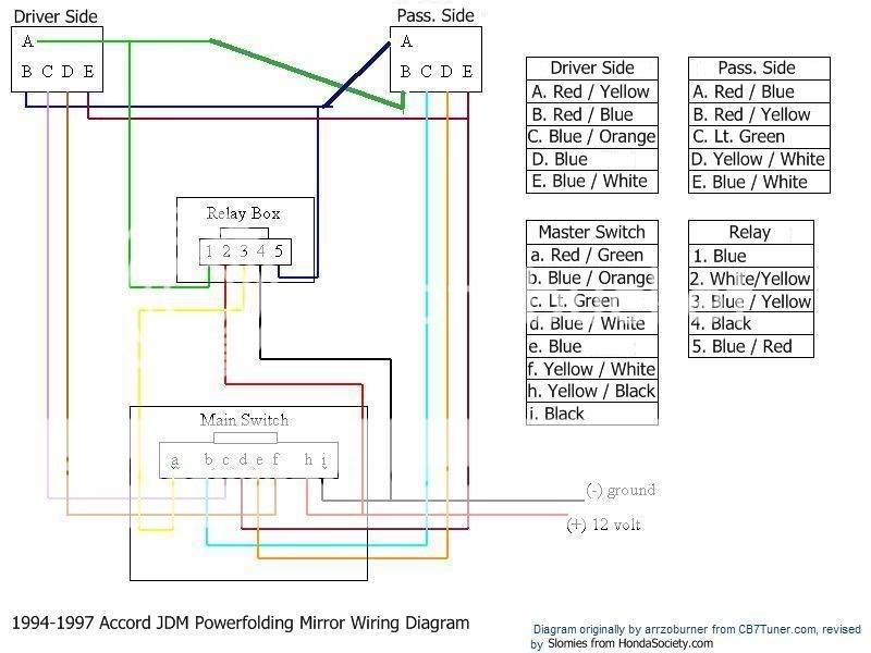
I finally hooked everything up in the car ... everything works! You have two options for wiring up the switch ...
OPTION 1: use the stock wiring. just de-pin the red / green wire from the jdm harness and put it where it belongs (see diagram above). next, connect the red / green wire to the blue / yellow wire on the relay.
OPTION 2: cut the stock harness off and splice in the jdm switch wiring. all the wires match up color wise except for 4 wires because the parts are from a jdm car and everything is backwards. also, connect the red / green wire to the blue / yellow wire on the relay. this is how the wires need to be switched around ...
<U>JDM Switch Wiring</U> --------------> <U>Stock Switch Wiring</U>
Blue / Orange -------------------> Lt. Green
Lt. Green ------------------------> Blue / Orange
Blue ------------------------------> Yellow / White
Yellow / White --------------- --> Blue
DON'T FORGET to change out the 7.5amp fuse in slot 7 (in the under dash fuse box) to a 10amp one as HateBreeder touched upon. Otherwise the second you try to use the powerfolding option, it will blow ... leaving you confused I made this mistake at first ...
Modified by Slomies at 11:57 AM 8/9/2007
I finally hooked everything up in the car ... everything works! You have two options for wiring up the switch ...
OPTION 1: use the stock wiring. just de-pin the red / green wire from the jdm harness and put it where it belongs (see diagram above). next, connect the red / green wire to the blue / yellow wire on the relay.
OPTION 2: cut the stock harness off and splice in the jdm switch wiring. all the wires match up color wise except for 4 wires because the parts are from a jdm car and everything is backwards. also, connect the red / green wire to the blue / yellow wire on the relay. this is how the wires need to be switched around ...
<U>JDM Switch Wiring</U> --------------> <U>Stock Switch Wiring</U>
Blue / Orange -------------------> Lt. Green
Lt. Green ------------------------> Blue / Orange
Blue ------------------------------> Yellow / White
Yellow / White --------------- --> Blue
DON'T FORGET to change out the 7.5amp fuse in slot 7 (in the under dash fuse box) to a 10amp one as HateBreeder touched upon. Otherwise the second you try to use the powerfolding option, it will blow ... leaving you confused
I made this mistake at first ...Modified by Slomies at 11:57 AM 8/9/2007
08-06-2007, 09:24 AM
#21
Honda-Tech Member
Thread Starter
Join Date: Feb 2007
Location: Milwaukee
Posts: 2,752
Likes: 0
Received 0 Likes
on
0 Posts
yes! thanks for the wiring diagram. Just as i figured there are a few different ways you can wire them in, Thanks for the info!
08-06-2007, 04:29 PM
#23
Junior Member
Join Date: Mar 2005
Location: NY
Posts: 492
Likes: 0
Received 0 Likes
on
0 Posts
honestly it isn't that hard. don't let it scare you. now if you didn't have a diagram, then i would be scared. i was a bit when i looked at the work that HateBreeder did, but nothing a lil determination didn't fix lol
08-10-2007, 02:02 PM
#24
Honda-Tech Member
Join Date: Apr 2004
Location: Buckeye Country, United States
Posts: 397
Likes: 0
Received 0 Likes
on
0 Posts
This guy above me mentioned on Gen5Alive to make sure and change the fuse for a bigger one. I think it was 10 amp? Forget the slot it's in. He knows.