

 03-25-2015, 09:26 AM
Last edit by: IB Advertising
See related guides and technical advice from our community experts:
Browse all: Engine and Powertrain
- Honda Accord: How to change serpentine belt
Step by step instructions for do-it-yourself repairs.
Browse all: Engine and Powertrain

How-To: Replace Timing Belt, Timing Balancer Belt and Water Pump on a F22B1
02-28-2007, 05:17 PM
#1
H-T Order of Merit
Thread Starter
This write-up and pictures is based on a F22B1 (94-97 EX) engine. For those of you with a F22Ax series engine, a F22B2 or a F23Ax series engine, this guide will give you a good idea of whats involved though the actual steps or alignment marks may be slightly different.
**Important Note**
If you have found yourself reading this write-up because you are replacing a timing belt that broke while the engine was running, you'll want to perform an additional step after installation of the new timing belt. Because these engines are what is called an interference engine, if the timing belt breaks while the engine is running there is a chance that the piston and valves could connect with each other causing damage to the valves. After installing the new timing belt you can do a compression test on each cylinder to make sure each cylinder is holding pressure. You are looking for a consistent psi across all cylinders in the 120psi range, anything obviously low could indicate a damaged valve. If you do find a bad cylinder, remove the head and have it inspected by a machine shop.
<u>Tool List</u>
- 1/4” Drive Ratchet
- 1/4” Drive 3” Extension
- 1/4” Drive 6pt Metric Sockets (8mm – 12mm)
- 1/4” Drive 6pt Metric Deep Sockets (8mm – 12mm)
- 3/8” Drive Ratchet
- 3/8” Drive 3” Extension
- 3/8” Drive 6” Extension
- 3/8” Drive 6pt Metric Sockets (10mm – 19mm)
- 3/8” Drive 6pt Metric Deep Sockets (10mm – 19mm)
- 1/2” Drive Ratchet
- 1/2” Drive 18” Breaker Bar
- 1/2” Drive 19mm 6pt Socket
- 1/2” Drive 20” Extension
- Metric Combination Wrenches (8mm-17mm) - Probably won’t use, but good to have on hand.
- Crankshaft Pulley Holding Tool
- Torque Wrench - Needs to be able to torque to 181 lbs-ft.
- P1 Phillips Head Screwdriver
- P2 Phillips Head Screwdriver
- Small Slotted Screwdriver
- Large Slotted Screwdriver
- Regular Pliers
- Needle Nose Pliers
- Floor Jack
- Jack Stands
- Block of Wood (see Step 7)
- 5’ Steel Pipe
- 18” Steel Pipe
- Funnel
<u>F22B1 Parts List</u>
- Timing Belt: 14400-P0A-004
- Timing Balancer Belt: 13405-PT0-0004
- Power Steering Belt: 56992-P0A-J02
- Alternator/Compressor Belt: 38920-P0A-J02
- Water Pump: 19200-P0A-003
- Front Balance Shaft Retainer Kit: 06923-P0A-306
- Valve Cover Gasket Kit: 12030-P0A-000
- Timing Belt Adjuster (Tensioner): 14510-PT0-004
- Timing Balancer Belt Adjuster (Tensioner): 13404-PT0-004
- Timing Belt Adjuster Spring: 13407-P0A-000
- Timing Balancer Belt Adjuster Spring: 14516-P0A-000
- Hondabond High-Temp Silicone Gasket Sealant: 08718-0001
<u>Step 1</u>
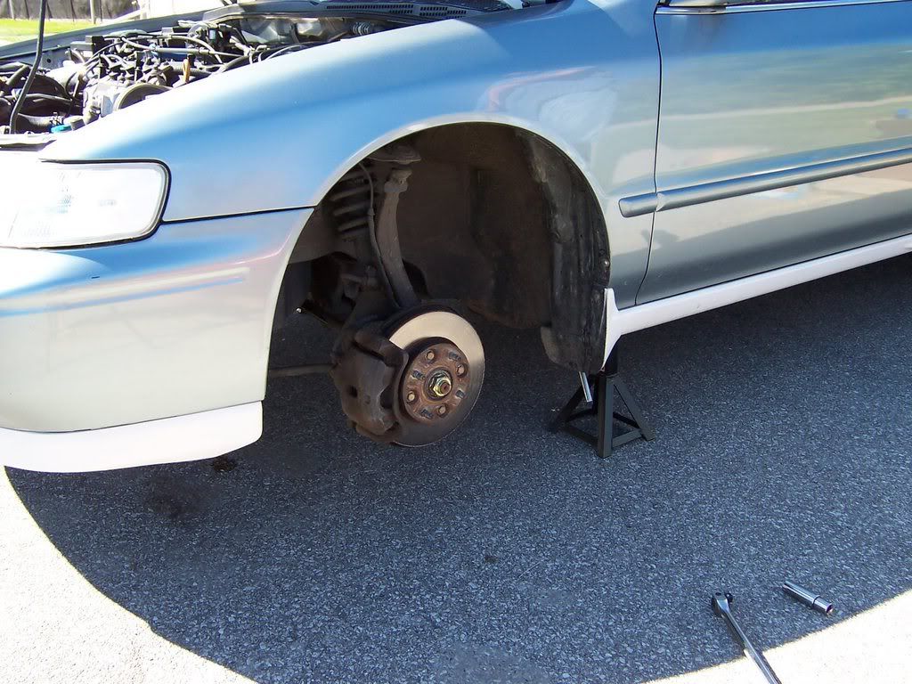
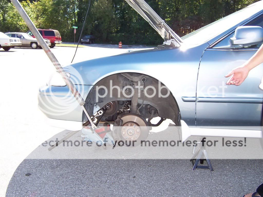
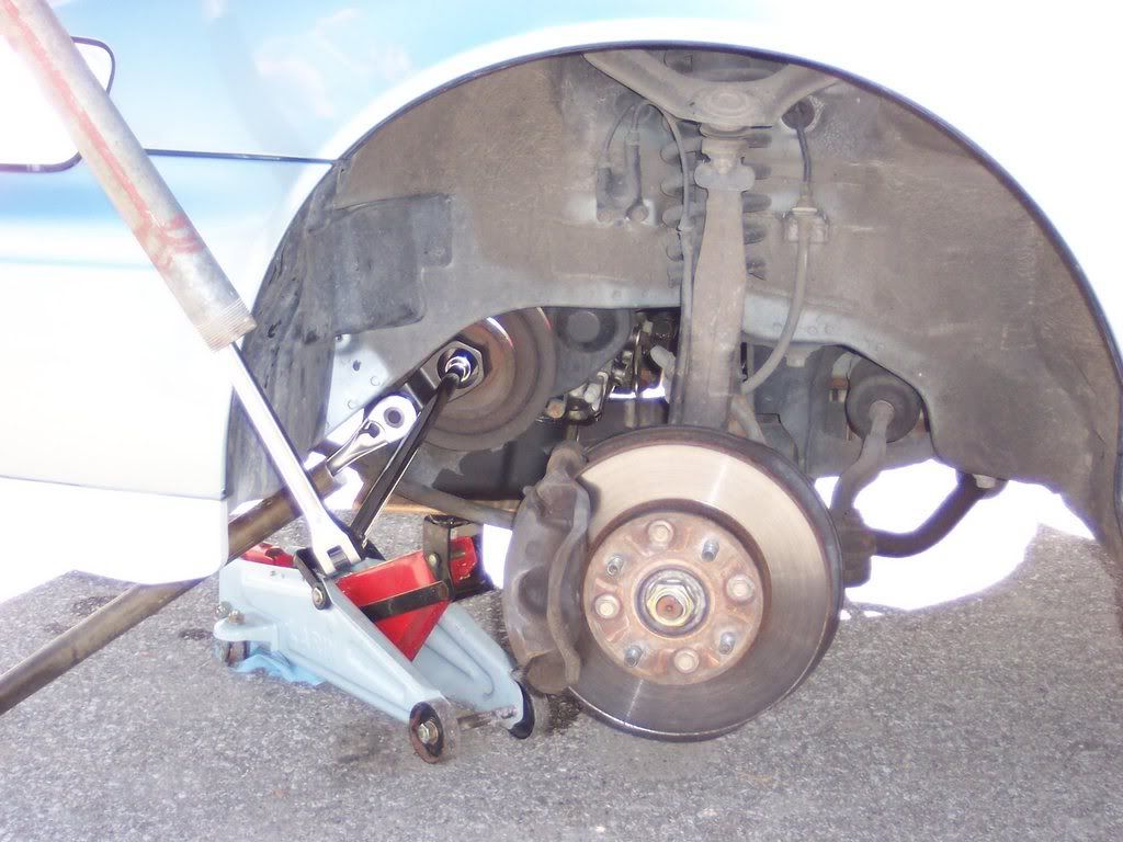
Loosen the lug nuts of the front wheels, lift and safely support the front of the car, then remove the front wheels. Be sure to pull the e-brake and block the rear wheels so the car doesn’t roll.

<u>Step 2</u>
Disconnect the negative side of the battery first, then positive.
<u>Step 3</u>
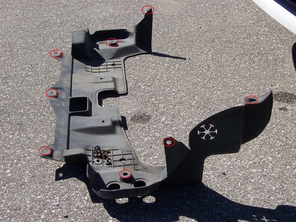
Remove the front splash shield. If memory serves me right there are 7 bolts and 1 push clip (located in the passenger side wheel well).

<u>Step 4</u>
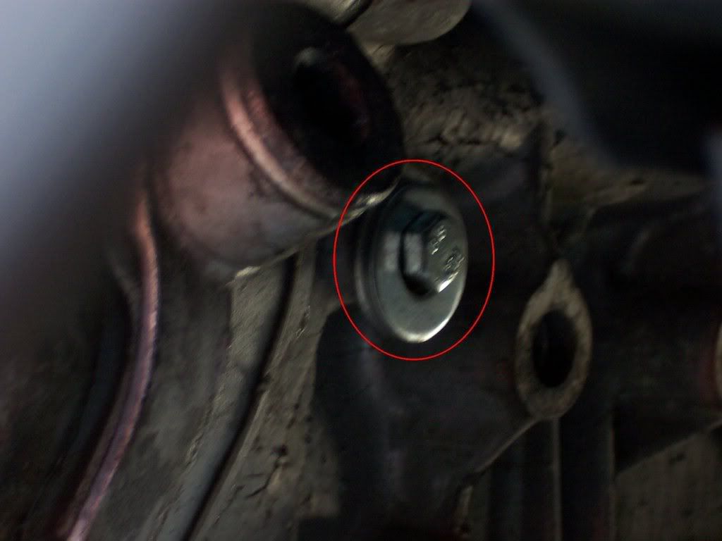
Loosen the adjusting bolt and mounting nuts, then remove the power steering belt.

Note:
- The mounting nut is shown in red and the adjusting nut is shown in yellow. One of the mounting nuts is not shown in the picture, just look below the one shown but on the opposite side.
- You can also unbolt the power steering pump if you wish to give yourself more room. We did this but we didn’t remove the PS hoses, just unbolted it from it’s bracket.
<u>Step 5</u>
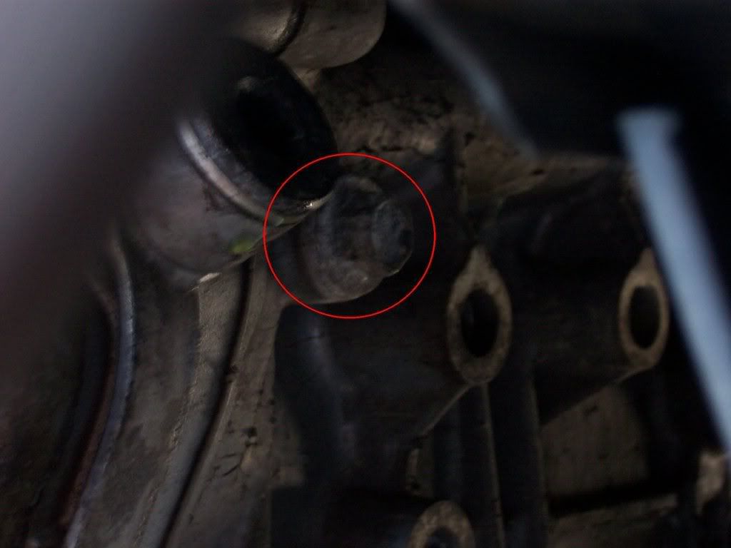
Loosen the adjusting bolt, mounting bolt and the locknut on the alternator, then remove the alternator belt.


Note:
- The yellow is the adjusting bolt.
- The green is the locknut.
- The red is the mounting bolt.
<u>Step 6</u>
Remove the alternator terminal and connector. Just move wires to an area out of the way.
<u>Step 7</u>
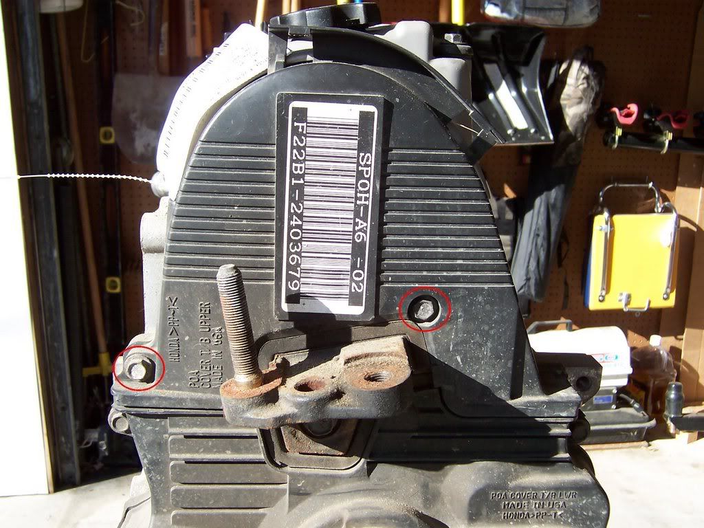
Place a jack under the engine and lift it to the oil pan but only putting a small amount of pressure on it. Make sure you place a block of wood between the oil pan and the jack so the oil pan doesn’t get damaged. This will support the engine while the drive side engine mount is removed. Now remove the driver side engine mount.
<u>Step 8</u>
Remove the oil dipstick and tube from the engine.
<u>Step 9</u>
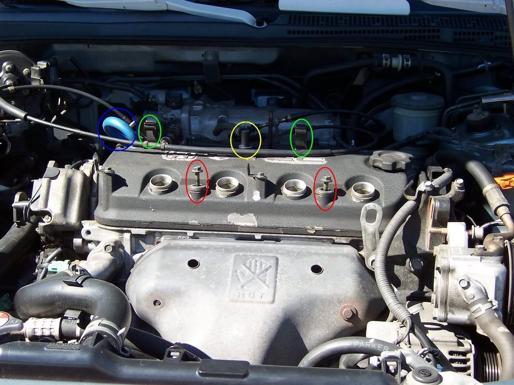
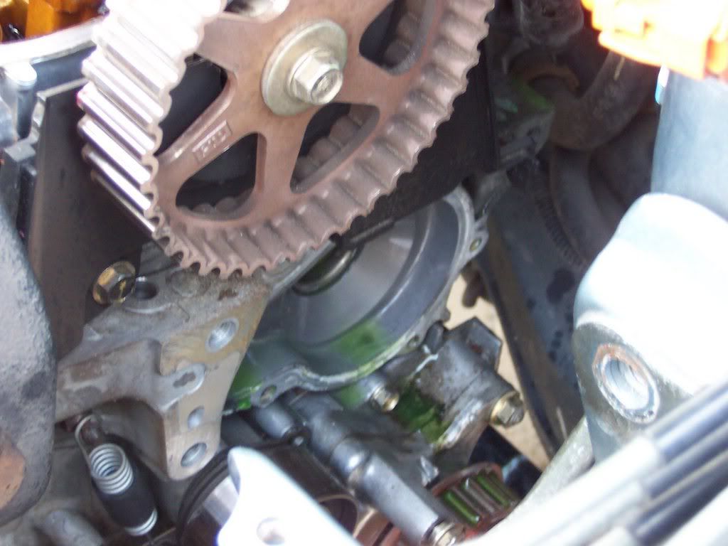
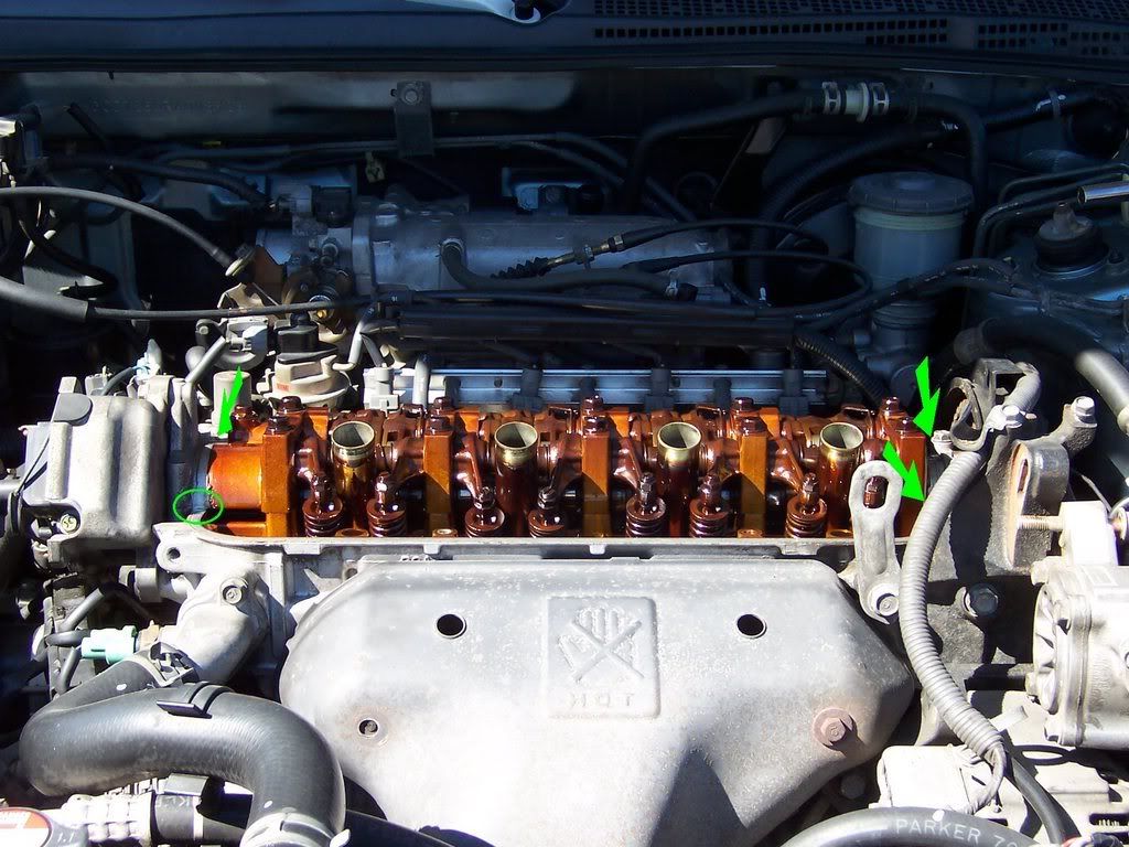
Remove the spark plug wires from the head and place them to the side out of the way. Remove the cruise control cable from the clips on the valve cover. Remove the PCV valve from the valve cover as well as the hose running from the valve cover to the intake tube. Now unbolt the 5 bolts and remove the valve cover from the head.

Note:
- Red is the valve cover bolts. 2 shown in front and 3 in back that is not shown.
- Yellow is the PCV valve.
- Green is the clips for the cruise control cable.
- Blue is the hose from the valve cover to the intake tube.
<u>Step 10</u>
Remove the crankshaft pulley bolt and the crankshaft pulley. In the following pictures you can see how we did it, we’ve done it this way a few times now and it’s worked great.


Tools Used:
- Crankshaft Pulley holding tool by Schley Products, bought at TheToolWarehouse.
(Update: the Schley Products 60100 tool is no longer available and has been redesigned, so I updated the link to the redesigned tool.)
- 1/2” drive ratchet connected to the pulley holding tool.
- 1/2” drive 19mm 6point socket.
- 1/2” drive 20” long extension bar.
- 1/2” drive 18” long breaker bar.
- 2 steel pipes. 1 about 5’ long and the other about 18” long.
<u>Step 11</u>
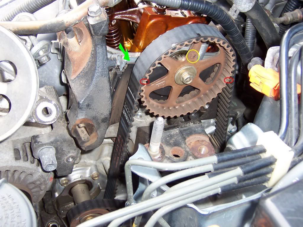
Remove the upper and lower side covers. Be sure not to lose the rubber seal around the adjusting nut.


Note:
- The red circles show the bolt locations.
- The yellow arrow is the rubber seal around the adjusting nut.
- The lower cover can be a pain but just be patient and work it around and you’ll be able to find a way to get it out, the radius rod gets in the way if I remember correctly.
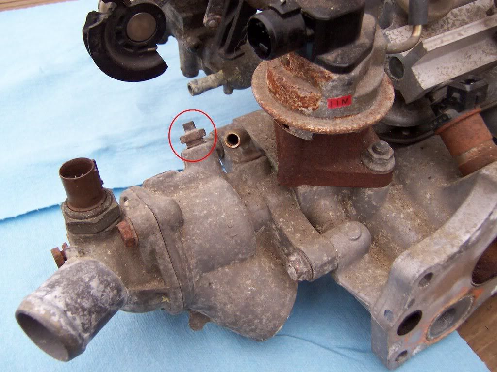
<u>Step 12</u>
Make sure that piston No.1 is at TDC (Top Dead Center). You do this by aligning the TDC marks of camshaft pulley with the plastic back cover. The “UP” mark should also be facing up at this time.

Note:
- The red circles shows the location of the TDC marks which I’ve drawn a thin black line across to help show where they are.
- The yellow circle shows the location of the UP mark.
- The green arrow shows the plastic back cover used to align the TDC marks.

You can also see the TDC and UP marks from the other side of the camshaft pulley as well.
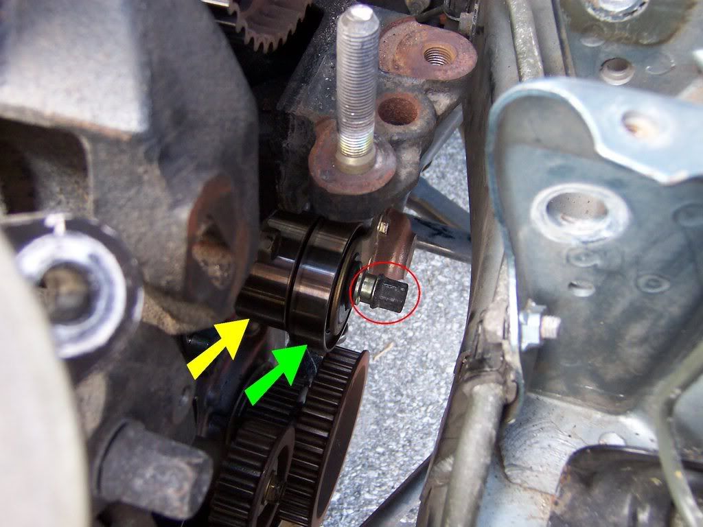
<u>Step 13</u>
Loosen the adjusting nut 2/3-1 turn, push the timing balancer belt tensioner up and the timing belt tensioner down, and then tighten the adjusting nut. This will release pressure on the belts allowing you to remove them.

Note:
- The red circle is the adjusting nut.
- The yellow arrow is the timing belt tensioner.
- The green arrow is the timing balancer belt tensioner.
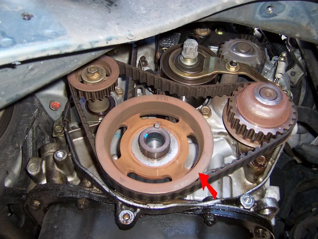
<u>Step 14</u>
Remove the timing balancer belt and timing belt. You’ll want to remove the timing balancer belt drive pulley as well, just slide it off once the timing balancer belt has been removed.

The red arrow is pointing to the timing balancer belt drive pulley.
<u>Step 15</u>
Drain the coolant. Under the radiator there is a white drain plug, loosen it and start draining the coolant. Otherwise you’ll end up with a big mess when you remove the water pump. After the coolant has been drained, tighten the drain plug. Be sure to clean up any spilled coolant.
<u>Step 16</u>
Remove the water pump.

As you can see, 1 of the bolts also has a spring hooked to it for the timing balancer belt tensioner so you’ll need either a deep socket or a wrench for that one.

That’s how it’ll look with the water pump removed. Be sure to clean up any spilled coolant, especially if you have animals around, it can kill them.
<u>Step 17</u>
Install the new water pump. Be sure to use a new gasket and torque all five bolts to 8.7 lbs-ft.
<u>Step 18</u>
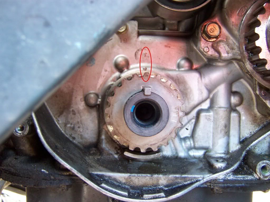
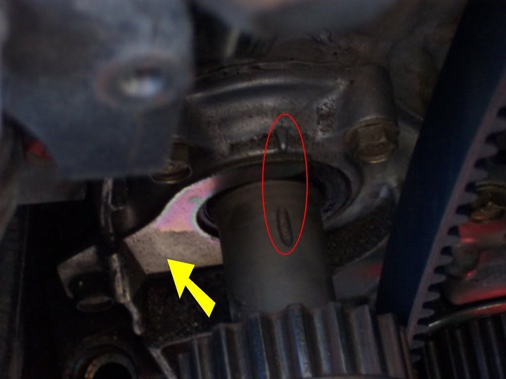
Set the timing belt drive pulley so that piston No.1 is at TDC. To do this, align the dimple on the tooth of the timing belt drive pulley with the pointer on the oil pump.

<u>Step 19</u>
Make sure the camshaft pulley is still set so that piston No.1 is at TDC (refer to Step 12)
<u>Step 20</u>
Install the timing belt tightly in the following order. 1. Timing Belt Drive Pulley (Crankshaft) > 2. Tensioner > 3. Water Pump Pulley > 4. Camshaft Pulley. While doing this, be sure to keep the timing belt drive pulley and camshaft pulley at TDC.
<u>Step 21</u>
Loosen and retighten the adjusting nut to tension the timing belt.
<u>Step 22</u>
Install the timing balancer belt drive pulley, the lower cover, the crankshaft pulley and tighten the crankshaft pulley bolt (no need to torque it yet).
<u>Step 23</u>
Rotate the crankshaft pulley 5-6 turns counterclockwise. This allows the timing belt to position onto the pulleys.
Tip:
- Remove the spark plugs to make it easier to rotate the engine.
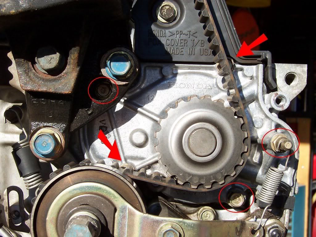
<u>Step 24</u>
Adjust the timing belt tension. Position piston No.1 at TDC (refer back to Step 12). Then loosen the adjusting nut 2/3-1 turn, rotate the crankshaft counterclockwise 3-TEETH on the CAMSHAFT and retighten the adjusting nut.
<u>Step 25</u>
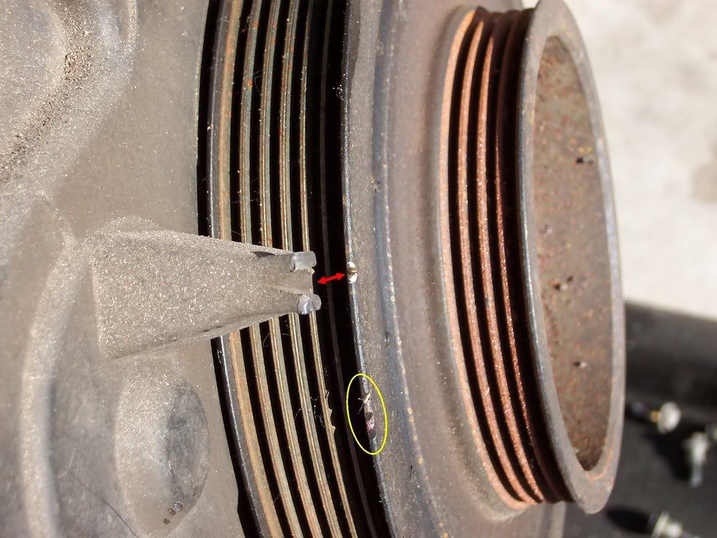
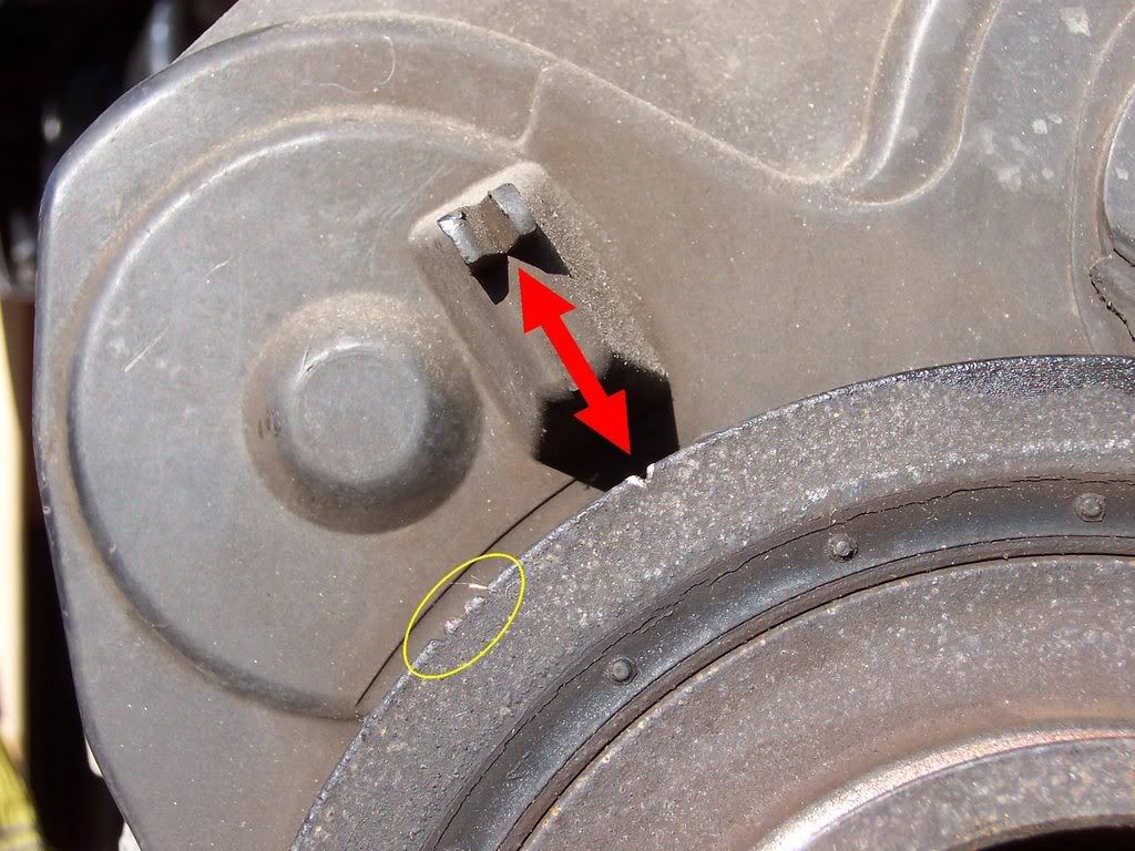
Make sure the camshaft pulley and crankshaft pulley is still at TDC.
- For the camshaft, refer to Step 12.
- On the crankshaft pulley you’ll see two sets of marks around the outside edge. 1 set has 3 marks (circled in yellow), the other is only 1 mark by itself. The mark by itself should line up with the pointer on the lower cover (shown by red arrows).


If the camshaft pulley or crankshaft pulley do not line up at TDC, remove the timing belt and go back to Step 18 and start over again.
<u>Step 26</u>
Remove the crankshaft pulley, lower cover and the timing balancer belt drive pulley.
<u>Step 27</u>
Make sure the timing belt drive pulley is set to TDC.
<u>Step 28</u>
Lock the timing belt tensioner in place by installing one of the 6x1.0mm bolt from the side covers.

<u>Step 29</u>
Loosen the adjusting nut 2/3-1 turn and verify the timing balancer belt tensioner moves freely. Push the timing balancer belt tensioner up and tighten the adjusting nut, this gives you room to install the timing balancer belt.
<u>Step 30</u>
Remove the sealing bolt from the maintenance hole and insert something long and skinny to hold the rear balance shaft pulley in place and aligned. The manual calls for a 6 x 100 mm bolt. A P1 phillips head screw driver should work, we use a long 6mm bolt though. You’ll be able to feel when the bolt or screwdriver is in place, the balance shaft won’t rotate when you try to rotate it.

That’s the sealing bolt for the maintenance hole you’ll be using.

That’s the bolt with a couple washers that we used to hold the balance shaft into position.
<u>Step 31</u>
Align the groove on the front balance shaft with the pointer on the oil pump housing.

The yellow arrow is pointing to the front balance shaft seal retainer which is a recall that should have already been done to your Accord, if not, make sure you get one. There are two different styles, so if yours looks a little different don’t worry about it, as long you have a retainer installed your fine.
<u>Step 32</u>
Install the timing balance belt drive pulley and the timing balance belt.
<u>Step 33</u>
Loosen the adjusting nut 2/3-1 turn to tension the timing balancer belt.
<u>Step 34</u>
Remove the bolt, screwdriver or whatever you used to hold the rear balance shaft in place and reinstall the 12mm sealing bolt into the maintenance hole at 22 lbs-ft.
<u>Step 35</u>
Install the crankshaft pulley and tighten the crankshaft pulley bolt.
<u>Step 36</u>
Turn the crankshaft pulley about one turn counterclockwise, then tighten the adjusting nut to 33 lbs-ft.
<u>Step 37</u>
Remove the 6mm bolt from the timing belt tensioner that you use to hold it in place in Step 28.
<u>Step 38</u>
Remove the crankshaft pulley and install the lower cover. Tighten the 6mm bolts that hold the lower cover to 8.7 lbs-ft.
<u>Step 39</u>
Reinstall the rubber seal around the adjusting nut but do not loosen the adjusting nut.
<u>Step 40</u>
Install the crankshaft pulley and tighten the crankshaft pulley bolt. Using the special tool you used to hold the pulley while loosening the pulley bolt, torque the pulley bolt to 181 lbs-ft.
<u>Step 41</u>
Install upper cover and tighten the 6mm bolts to 8.7 lbs-ft.
<u>Step 42</u>
Install the valve cover with a new valve cover gasket. Before installing the new valve cover and gasket, put some Hondabond gasket sealer in the four corners where the gasket goes over the camshaft.

Torque the 5 valve cover bolts to 7.2 lbs-ft. Be careful though, the valve cover bolt can snap real easy, do not over torque them.
<u>Step 43</u>
With the jack that’s still under the engine, raise the engine and align the driver side engine mount. Torque the mounting bolts/nuts to 47 lbs-ft.
<u>Step 44</u>
Reinstall the alternator belt and adjust the tension of the belt so that the deflection is about 1/2” when measured between the alternator pulley and crankshaft pulley. Once the tension is adjusted, tighten the locknut to 16 lbs-ft and the mounting bolt to 33 lbs-ft.
<u>Step 45</u>
Reconnect the alternator terminal and connector to the alternator. Tighten the alternator terminal to 6 lbs-ft.
<u>Step 46</u>
Reinstall the power steering belt and adjust the tension of the belt so that the deflection is about 1/2” when measured between the power steering pulley and the crankshaft pulley. Once the tension is adjusted, tighten the mounting nuts to 16 lbs-ft.
<u>Step 47</u>
Reinstall the front splash shield, tighten the bolts to 7.2 lbs-ft.
<u>Step 48</u>
Reinstall the front wheels and torque the lug nuts to 80 lbs-ft in a crossing pattern.
<u>Step 49</u>
Raise the car, remove the jack stands and lower the car back down.
<u>Step 50</u>
Loosen the air bleed bolt on the thermostat housing.

Fill the radiator to the bottom of the filler neck with coolant. Fit a hose over bleeder bolt and hang it into a cup. Tighten the bleeder bolt to 7 lbs-ft as soon as coolant starts to run out in a steady stream without any air bubbles.
<u>Step 51</u>
With the radiator cap off, start the engine and run until warmed up (radiator fan comes on at least twice). Be sure to have the heat temperature control dial turned all the way to maximum heat. Once warmed up, turn the engine off. If needed, add more coolant to bring the level back up to the bottom of the filler neck.
<u>Step 52</u>
Put the radiator cap on tightly and run the engine again while checking for any leaks.
I hope this is of some help to some people. If anyone notices something I stated wrong, please let me know so I can correct the mistake.
To download a PDF version of this how-to, please follow the link below:
F22B1 Timing Belt How-To
**If I've already sent this to anyone earlier, please download this one, I have made changes and added pictures**
**Important Note**
If you have found yourself reading this write-up because you are replacing a timing belt that broke while the engine was running, you'll want to perform an additional step after installation of the new timing belt. Because these engines are what is called an interference engine, if the timing belt breaks while the engine is running there is a chance that the piston and valves could connect with each other causing damage to the valves. After installing the new timing belt you can do a compression test on each cylinder to make sure each cylinder is holding pressure. You are looking for a consistent psi across all cylinders in the 120psi range, anything obviously low could indicate a damaged valve. If you do find a bad cylinder, remove the head and have it inspected by a machine shop.
<u>Tool List</u>
- 1/4” Drive Ratchet
- 1/4” Drive 3” Extension
- 1/4” Drive 6pt Metric Sockets (8mm – 12mm)
- 1/4” Drive 6pt Metric Deep Sockets (8mm – 12mm)
- 3/8” Drive Ratchet
- 3/8” Drive 3” Extension
- 3/8” Drive 6” Extension
- 3/8” Drive 6pt Metric Sockets (10mm – 19mm)
- 3/8” Drive 6pt Metric Deep Sockets (10mm – 19mm)
- 1/2” Drive Ratchet
- 1/2” Drive 18” Breaker Bar
- 1/2” Drive 19mm 6pt Socket
- 1/2” Drive 20” Extension
- Metric Combination Wrenches (8mm-17mm) - Probably won’t use, but good to have on hand.
- Crankshaft Pulley Holding Tool
- Torque Wrench - Needs to be able to torque to 181 lbs-ft.
- P1 Phillips Head Screwdriver
- P2 Phillips Head Screwdriver
- Small Slotted Screwdriver
- Large Slotted Screwdriver
- Regular Pliers
- Needle Nose Pliers
- Floor Jack
- Jack Stands
- Block of Wood (see Step 7)
- 5’ Steel Pipe
- 18” Steel Pipe
- Funnel
<u>F22B1 Parts List</u>
- Timing Belt: 14400-P0A-004
- Timing Balancer Belt: 13405-PT0-0004
- Power Steering Belt: 56992-P0A-J02
- Alternator/Compressor Belt: 38920-P0A-J02
- Water Pump: 19200-P0A-003
- Front Balance Shaft Retainer Kit: 06923-P0A-306
- Valve Cover Gasket Kit: 12030-P0A-000
- Timing Belt Adjuster (Tensioner): 14510-PT0-004
- Timing Balancer Belt Adjuster (Tensioner): 13404-PT0-004
- Timing Belt Adjuster Spring: 13407-P0A-000
- Timing Balancer Belt Adjuster Spring: 14516-P0A-000
- Hondabond High-Temp Silicone Gasket Sealant: 08718-0001
<u>Step 1</u>
Loosen the lug nuts of the front wheels, lift and safely support the front of the car, then remove the front wheels. Be sure to pull the e-brake and block the rear wheels so the car doesn’t roll.
<u>Step 2</u>
Disconnect the negative side of the battery first, then positive.
<u>Step 3</u>
Remove the front splash shield. If memory serves me right there are 7 bolts and 1 push clip (located in the passenger side wheel well).
<u>Step 4</u>
Loosen the adjusting bolt and mounting nuts, then remove the power steering belt.
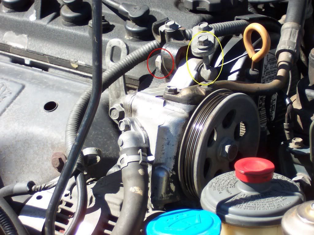
Note:
- The mounting nut is shown in red and the adjusting nut is shown in yellow. One of the mounting nuts is not shown in the picture, just look below the one shown but on the opposite side.
- You can also unbolt the power steering pump if you wish to give yourself more room. We did this but we didn’t remove the PS hoses, just unbolted it from it’s bracket.
<u>Step 5</u>
Loosen the adjusting bolt, mounting bolt and the locknut on the alternator, then remove the alternator belt.
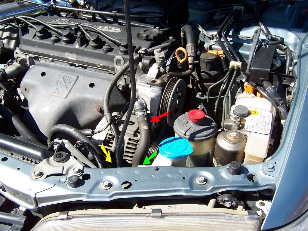

Note:
- The yellow is the adjusting bolt.
- The green is the locknut.
- The red is the mounting bolt.
<u>Step 6</u>
Remove the alternator terminal and connector. Just move wires to an area out of the way.
<u>Step 7</u>
Place a jack under the engine and lift it to the oil pan but only putting a small amount of pressure on it. Make sure you place a block of wood between the oil pan and the jack so the oil pan doesn’t get damaged. This will support the engine while the drive side engine mount is removed. Now remove the driver side engine mount.
<u>Step 8</u>
Remove the oil dipstick and tube from the engine.
<u>Step 9</u>
Remove the spark plug wires from the head and place them to the side out of the way. Remove the cruise control cable from the clips on the valve cover. Remove the PCV valve from the valve cover as well as the hose running from the valve cover to the intake tube. Now unbolt the 5 bolts and remove the valve cover from the head.
Note:
- Red is the valve cover bolts. 2 shown in front and 3 in back that is not shown.
- Yellow is the PCV valve.
- Green is the clips for the cruise control cable.
- Blue is the hose from the valve cover to the intake tube.
<u>Step 10</u>
Remove the crankshaft pulley bolt and the crankshaft pulley. In the following pictures you can see how we did it, we’ve done it this way a few times now and it’s worked great.
Tools Used:
- Crankshaft Pulley holding tool by Schley Products, bought at TheToolWarehouse.
(Update: the Schley Products 60100 tool is no longer available and has been redesigned, so I updated the link to the redesigned tool.)
- 1/2” drive ratchet connected to the pulley holding tool.
- 1/2” drive 19mm 6point socket.
- 1/2” drive 20” long extension bar.
- 1/2” drive 18” long breaker bar.
- 2 steel pipes. 1 about 5’ long and the other about 18” long.
<u>Step 11</u>
Remove the upper and lower side covers. Be sure not to lose the rubber seal around the adjusting nut.

Note:
- The red circles show the bolt locations.
- The yellow arrow is the rubber seal around the adjusting nut.
- The lower cover can be a pain but just be patient and work it around and you’ll be able to find a way to get it out, the radius rod gets in the way if I remember correctly.
<u>Step 12</u>
Make sure that piston No.1 is at TDC (Top Dead Center). You do this by aligning the TDC marks of camshaft pulley with the plastic back cover. The “UP” mark should also be facing up at this time.
Note:
- The red circles shows the location of the TDC marks which I’ve drawn a thin black line across to help show where they are.
- The yellow circle shows the location of the UP mark.
- The green arrow shows the plastic back cover used to align the TDC marks.

You can also see the TDC and UP marks from the other side of the camshaft pulley as well.
<u>Step 13</u>
Loosen the adjusting nut 2/3-1 turn, push the timing balancer belt tensioner up and the timing belt tensioner down, and then tighten the adjusting nut. This will release pressure on the belts allowing you to remove them.
Note:
- The red circle is the adjusting nut.
- The yellow arrow is the timing belt tensioner.
- The green arrow is the timing balancer belt tensioner.
<u>Step 14</u>
Remove the timing balancer belt and timing belt. You’ll want to remove the timing balancer belt drive pulley as well, just slide it off once the timing balancer belt has been removed.
The red arrow is pointing to the timing balancer belt drive pulley.
<u>Step 15</u>
Drain the coolant. Under the radiator there is a white drain plug, loosen it and start draining the coolant. Otherwise you’ll end up with a big mess when you remove the water pump. After the coolant has been drained, tighten the drain plug. Be sure to clean up any spilled coolant.
<u>Step 16</u>
Remove the water pump.
As you can see, 1 of the bolts also has a spring hooked to it for the timing balancer belt tensioner so you’ll need either a deep socket or a wrench for that one.
That’s how it’ll look with the water pump removed. Be sure to clean up any spilled coolant, especially if you have animals around, it can kill them.
<u>Step 17</u>
Install the new water pump. Be sure to use a new gasket and torque all five bolts to 8.7 lbs-ft.
<u>Step 18</u>
Set the timing belt drive pulley so that piston No.1 is at TDC. To do this, align the dimple on the tooth of the timing belt drive pulley with the pointer on the oil pump.
<u>Step 19</u>
Make sure the camshaft pulley is still set so that piston No.1 is at TDC (refer to Step 12)
<u>Step 20</u>
Install the timing belt tightly in the following order. 1. Timing Belt Drive Pulley (Crankshaft) > 2. Tensioner > 3. Water Pump Pulley > 4. Camshaft Pulley. While doing this, be sure to keep the timing belt drive pulley and camshaft pulley at TDC.
<u>Step 21</u>
Loosen and retighten the adjusting nut to tension the timing belt.
<u>Step 22</u>
Install the timing balancer belt drive pulley, the lower cover, the crankshaft pulley and tighten the crankshaft pulley bolt (no need to torque it yet).
<u>Step 23</u>
Rotate the crankshaft pulley 5-6 turns counterclockwise. This allows the timing belt to position onto the pulleys.
Tip:
- Remove the spark plugs to make it easier to rotate the engine.
<u>Step 24</u>
Adjust the timing belt tension. Position piston No.1 at TDC (refer back to Step 12). Then loosen the adjusting nut 2/3-1 turn, rotate the crankshaft counterclockwise 3-TEETH on the CAMSHAFT and retighten the adjusting nut.
<u>Step 25</u>
Make sure the camshaft pulley and crankshaft pulley is still at TDC.
- For the camshaft, refer to Step 12.
- On the crankshaft pulley you’ll see two sets of marks around the outside edge. 1 set has 3 marks (circled in yellow), the other is only 1 mark by itself. The mark by itself should line up with the pointer on the lower cover (shown by red arrows).
If the camshaft pulley or crankshaft pulley do not line up at TDC, remove the timing belt and go back to Step 18 and start over again.
<u>Step 26</u>
Remove the crankshaft pulley, lower cover and the timing balancer belt drive pulley.
<u>Step 27</u>
Make sure the timing belt drive pulley is set to TDC.
<u>Step 28</u>
Lock the timing belt tensioner in place by installing one of the 6x1.0mm bolt from the side covers.

<u>Step 29</u>
Loosen the adjusting nut 2/3-1 turn and verify the timing balancer belt tensioner moves freely. Push the timing balancer belt tensioner up and tighten the adjusting nut, this gives you room to install the timing balancer belt.
<u>Step 30</u>
Remove the sealing bolt from the maintenance hole and insert something long and skinny to hold the rear balance shaft pulley in place and aligned. The manual calls for a 6 x 100 mm bolt. A P1 phillips head screw driver should work, we use a long 6mm bolt though. You’ll be able to feel when the bolt or screwdriver is in place, the balance shaft won’t rotate when you try to rotate it.
That’s the sealing bolt for the maintenance hole you’ll be using.
That’s the bolt with a couple washers that we used to hold the balance shaft into position.
<u>Step 31</u>
Align the groove on the front balance shaft with the pointer on the oil pump housing.
The yellow arrow is pointing to the front balance shaft seal retainer which is a recall that should have already been done to your Accord, if not, make sure you get one. There are two different styles, so if yours looks a little different don’t worry about it, as long you have a retainer installed your fine.
<u>Step 32</u>
Install the timing balance belt drive pulley and the timing balance belt.
<u>Step 33</u>
Loosen the adjusting nut 2/3-1 turn to tension the timing balancer belt.
<u>Step 34</u>
Remove the bolt, screwdriver or whatever you used to hold the rear balance shaft in place and reinstall the 12mm sealing bolt into the maintenance hole at 22 lbs-ft.
<u>Step 35</u>
Install the crankshaft pulley and tighten the crankshaft pulley bolt.
<u>Step 36</u>
Turn the crankshaft pulley about one turn counterclockwise, then tighten the adjusting nut to 33 lbs-ft.
<u>Step 37</u>
Remove the 6mm bolt from the timing belt tensioner that you use to hold it in place in Step 28.
<u>Step 38</u>
Remove the crankshaft pulley and install the lower cover. Tighten the 6mm bolts that hold the lower cover to 8.7 lbs-ft.
<u>Step 39</u>
Reinstall the rubber seal around the adjusting nut but do not loosen the adjusting nut.
<u>Step 40</u>
Install the crankshaft pulley and tighten the crankshaft pulley bolt. Using the special tool you used to hold the pulley while loosening the pulley bolt, torque the pulley bolt to 181 lbs-ft.
<u>Step 41</u>
Install upper cover and tighten the 6mm bolts to 8.7 lbs-ft.
<u>Step 42</u>
Install the valve cover with a new valve cover gasket. Before installing the new valve cover and gasket, put some Hondabond gasket sealer in the four corners where the gasket goes over the camshaft.
Torque the 5 valve cover bolts to 7.2 lbs-ft. Be careful though, the valve cover bolt can snap real easy, do not over torque them.
<u>Step 43</u>
With the jack that’s still under the engine, raise the engine and align the driver side engine mount. Torque the mounting bolts/nuts to 47 lbs-ft.
<u>Step 44</u>
Reinstall the alternator belt and adjust the tension of the belt so that the deflection is about 1/2” when measured between the alternator pulley and crankshaft pulley. Once the tension is adjusted, tighten the locknut to 16 lbs-ft and the mounting bolt to 33 lbs-ft.
<u>Step 45</u>
Reconnect the alternator terminal and connector to the alternator. Tighten the alternator terminal to 6 lbs-ft.
<u>Step 46</u>
Reinstall the power steering belt and adjust the tension of the belt so that the deflection is about 1/2” when measured between the power steering pulley and the crankshaft pulley. Once the tension is adjusted, tighten the mounting nuts to 16 lbs-ft.
<u>Step 47</u>
Reinstall the front splash shield, tighten the bolts to 7.2 lbs-ft.
<u>Step 48</u>
Reinstall the front wheels and torque the lug nuts to 80 lbs-ft in a crossing pattern.
<u>Step 49</u>
Raise the car, remove the jack stands and lower the car back down.
<u>Step 50</u>
Loosen the air bleed bolt on the thermostat housing.
Fill the radiator to the bottom of the filler neck with coolant. Fit a hose over bleeder bolt and hang it into a cup. Tighten the bleeder bolt to 7 lbs-ft as soon as coolant starts to run out in a steady stream without any air bubbles.
<u>Step 51</u>
With the radiator cap off, start the engine and run until warmed up (radiator fan comes on at least twice). Be sure to have the heat temperature control dial turned all the way to maximum heat. Once warmed up, turn the engine off. If needed, add more coolant to bring the level back up to the bottom of the filler neck.
<u>Step 52</u>
Put the radiator cap on tightly and run the engine again while checking for any leaks.
I hope this is of some help to some people. If anyone notices something I stated wrong, please let me know so I can correct the mistake.
To download a PDF version of this how-to, please follow the link below:
F22B1 Timing Belt How-To
**If I've already sent this to anyone earlier, please download this one, I have made changes and added pictures**
Last edited by tech8; 02-12-2024 at 05:42 PM. Reason: Replaced dead link with Wayback Machine link

The following users liked this post:
03-01-2007, 09:37 AM
#2
Honda-Tech Member
Great write up! I didn't expect anyone to take the time for a write up that's this involved/lengthy. 
03-01-2007, 09:43 AM
#3
Honda-Tech Member
Gorgeous man. I was going to do this write up myself this weekend since I couldn't find a clean one with pics.
:EDIT: Still might do the write up for 6th gen if there's interest.
I was going to do this write up myself this weekend since I couldn't find a clean one with pics. :EDIT: Still might do the write up for 6th gen if there's interest.
03-01-2007, 10:17 AM
#4
H-T Order of Merit
Thread Starter
Thanks! I appreciate it.
I had these pictures from a couple years ago and figured if I was going to do a write-up that I would be as descriptive as possible since it is an involved job to do.
AFAccord,
I'm not familiar with the exact steps/alignments for the F23Ax engines so if they are slightly different then it may be a good idea to do a write-up anyway. I'm sure it's similar but if there is something different, some people may prefer to actually see a timing belt how-to on their exact engine. If you do, let me know so I can add it to the FAQ.
I appreciate it.I had these pictures from a couple years ago and figured if I was going to do a write-up that I would be as descriptive as possible since it is an involved job to do.
AFAccord,
I'm not familiar with the exact steps/alignments for the F23Ax engines so if they are slightly different then it may be a good idea to do a write-up anyway. I'm sure it's similar but if there is something different, some people may prefer to actually see a timing belt how-to on their exact engine. If you do, let me know so I can add it to the FAQ.
03-01-2007, 10:39 AM
#6
Honda-Tech Member
FAQ THIS.
IF there is any thread the warrants stickiness, here it is.
IF there is any thread the warrants stickiness, here it is.
03-01-2007, 11:03 AM
#7
H-T Order of Merit
Thread Starter
Thanks
I added this to the FAQ right after I post it
I added this to the FAQ right after I post it
Trending Topics
03-01-2007, 12:46 PM
#10
H-T Order of Merit
Thread Starter
Thanks
Also, I have this in a PDF version with pictures and everything if anyone is interested. It is 12 pages long and about 7.7mb in size. I just don't have anywhere to host it. I figured this would be nice for people who want to print it out and have it with them while working on their car.
Also, I have this in a PDF version with pictures and everything if anyone is interested. It is 12 pages long and about 7.7mb in size. I just don't have anywhere to host it. I figured this would be nice for people who want to print it out and have it with them while working on their car.
03-01-2007, 01:22 PM
#11
Honda-Tech Member
Join Date: Aug 2002
Posts: 397
Likes: 0
Received 0 Likes
on
0 Posts
This is an AWESOME write-up!!!! I didn't do step 15 (dumb me) and of course I had coolant all over the garage. In step 3 I only took out a couple of bolts and just folded back the splash shield. Can you elaborate on installing the water pump (i.e. what tools/sockets/extensions you used), it was really hard for me to reinstall the water pump for some reason. Also, elaborate on reinstalling the lower timing belt cover, that is a bitch to get back on. A mod you guys might want to do is trim the lip on the upper timing belt cover so in the future you can remove it without taking the valve cover off. If you have changed the oil seals, do a write-up on that too. 
Great work!
Great work!
03-01-2007, 02:06 PM
#12
H-T Order of Merit
Thread Starter
Well, we did this in late September of 2004 I believe so lets see...
For the water pump, I believe we just used a 10mm deep socket to remove the one special bolt and a regular 10mm socket for the other 4. Since the bolts aren't torqued real tight, I'm pretty sure we were using a 1/4" drive ratchet in there. From what I can remember though, there wasn't any problems putting the new water pump back in. Just a simple unbolt, wipe clean, bolt the new one in.
ah, the lower timing belt cover. I knew someone was going to ask about that one. For the life of me I can't remember the exact route we took to get it in and out. I remember the radius rod got in the way and we had to play with it a bit the first time, then we found the way to get it in and out, I just can't remember it exactly. It's just something that going to be a trial and error, just play with it until you figure the best way out.
I agree that trimming the lip of the upper timing belt cover would be nice for those with adjustable cam gears. Much better than cutting a big hole in it IMO.
You know, I thought about the oil seals when I was writing this up yesterday and I can't remember if we did them or not. I want to say we did but I don't have any pictures or it, maybe we didn't , it was over 2 years ago. But yes, those should be replaced at this as well while everything is apart and accessible.
For the water pump, I believe we just used a 10mm deep socket to remove the one special bolt and a regular 10mm socket for the other 4. Since the bolts aren't torqued real tight, I'm pretty sure we were using a 1/4" drive ratchet in there. From what I can remember though, there wasn't any problems putting the new water pump back in. Just a simple unbolt, wipe clean, bolt the new one in.
ah, the lower timing belt cover. I knew someone was going to ask about that one. For the life of me I can't remember the exact route we took to get it in and out. I remember the radius rod got in the way and we had to play with it a bit the first time, then we found the way to get it in and out, I just can't remember it exactly. It's just something that going to be a trial and error, just play with it until you figure the best way out.
I agree that trimming the lip of the upper timing belt cover would be nice for those with adjustable cam gears. Much better than cutting a big hole in it IMO.
You know, I thought about the oil seals when I was writing this up yesterday and I can't remember if we did them or not. I want to say we did but I don't have any pictures or it, maybe we didn't
, it was over 2 years ago. But yes, those should be replaced at this as well while everything is apart and accessible.
03-03-2007, 01:20 PM
#16
H-T Order of Merit
Thread Starter
uh, does everyone want it stickied? It is in the FAQ, first link in the Engine section.
Yeah, I have the PDF done. I emailed it to SuperSlow already. IM me.
Yeah, I have the PDF done. I emailed it to SuperSlow already. IM me.
03-14-2007, 06:13 PM
#18
H-T Order of Merit
Thread Starter
you should.
I mean, do you really want to chance it and have to take everything back apart or worse if it snaps? Worse case is that belt snaps and gets caught up in the timing belt, that would be bad. Not something I'm willing to take a chance on, regardless of how slim the chances of that happening are.
I mean, do you really want to chance it and have to take everything back apart or worse if it snaps? Worse case is that belt snaps and gets caught up in the timing belt, that would be bad. Not something I'm willing to take a chance on, regardless of how slim the chances of that happening are.
03-14-2007, 06:21 PM
#19
<TABLE WIDTH="90%" CELLSPACING=0 CELLPADDING=0 ALIGN=CENTER><TR><TD>Quote, originally posted by mxl36o »</TD></TR><TR><TD CLASS="quote">is it really important to change the balancer belt?</TD></TR></TABLE>Well, for the '94 GSR in your signature, no you don't have to change the balancer belt. 
If you have an F-series engine, just remember that the balancer belt has just about as many miles on it as the timing belt.
Touring...
Nice job. Looks pretty close for a '92 and '98, as far as the important stuff.
If you have an F-series engine, just remember that the balancer belt has just about as many miles on it as the timing belt.
Touring...
Nice job. Looks pretty close for a '92 and '98, as far as the important stuff.
03-14-2007, 06:35 PM
#20
H-T Order of Merit
Thread Starter
<TABLE WIDTH="90%" CELLSPACING=0 CELLPADDING=0 ALIGN=CENTER><TR><TD>Quote, originally posted by JimBlake »</TD></TR><TR><TD CLASS="quote">Touring...
Nice job. Looks pretty close for a '92 and '98, as far as the important stuff.
</TD></TR></TABLE>
Thanks
I figured it would be close but wasn't sure since I've never done one on those years.
Nice job. Looks pretty close for a '92 and '98, as far as the important stuff.
</TD></TR></TABLE>
Thanks
I figured it would be close but wasn't sure since I've never done one on those years.
03-16-2007, 05:30 AM
#23
H-T Order of Merit
Thread Starter
<TABLE WIDTH="90%" CELLSPACING=0 CELLPADDING=0 ALIGN=CENTER><TR><TD>Quote, originally posted by mxl36o »</TD></TR><TR><TD CLASS="quote">just a suggestion... start with a list of tools and list of parts needed...at the top.</TD></TR></TABLE>
hmm, ok, I may move the parts list to the top, but as for a list of the tools needed... that may be a problem. We did this in, I believe, late September 2004 so it's a bit hard to remember the exact tools we used. But I'll try to come up with a list and add that. Thanks for the suggestion.
<TABLE WIDTH="90%" CELLSPACING=0 CELLPADDING=0 ALIGN=CENTER><TR><TD>Quote, originally posted by mxl36o »</TD></TR><TR><TD CLASS="quote">GREAT write up</TD></TR></TABLE>
Thanks!
<TABLE WIDTH="90%" CELLSPACING=0 CELLPADDING=0 ALIGN=CENTER><TR><TD>Quote, originally posted by mxl36o »</TD></TR><TR><TD CLASS="quote">how long would this take an amature to accomplish?</TD></TR></TABLE>
Maybe 4 hours? I would just allow the whole day so you don't rush anything. Start early, take you time and double or even triple check everything upon installation. You don't want to rush it and make a mistake. Once you have the crank pulley bolt loose, it's pretty down hill from there IMO. If you get that loose, you can do the rest it just takes time.
03-16-2007, 07:30 AM
#24
<TABLE WIDTH="90%" CELLSPACING=0 CELLPADDING=0 ALIGN=CENTER><TR><TD>Quote, originally posted by TouringAccord »</TD></TR><TR><TD CLASS="quote">... but as for a list of the tools needed... that may be a problem...</TD></TR></TABLE>Most are general hand tools. If you try to list the exact size sockets, that stuff can vary over the different model-years. Maybe it's easier to list only the unusual stuff. Start a list...
Crank-holding tool -or- big powerful air-impact wrench.
Scissors jack & scrap wood under oil pan (while engine mount is removed).
Crank-holding tool -or- big powerful air-impact wrench.
Scissors jack & scrap wood under oil pan (while engine mount is removed).
03-16-2007, 07:36 AM
#25
H-T Order of Merit
Thread Starter
yeah, I figured trying to be too specific might get overly complicated and that I would just end up doing a general list like 10mm-19mm 3/8" drive socket set or something along those lines.
I have the tools to remove the crank pulley bolt listed at that step of the process. But I'll probably just add them to the list of tools but also leave them at that step so people know what tools I used to do that step since it is a commonly asked question at times.
I have the tools to remove the crank pulley bolt listed at that step of the process. But I'll probably just add them to the list of tools but also leave them at that step so people know what tools I used to do that step since it is a commonly asked question at times.