
Alternator Not Charging
 04-20-2014, 12:45 PM
#1
Trial User
Thread Starter

Join Date: Apr 2014
Posts: 2
Likes: 0
Received 0 Likes
on
0 Posts
I've been chasing a charging issue for quite a while now. I bought a new re-manufactured alternator over the winter, but it just wouldn't charge my new battery. After several auto store checks, they said it was good. This past week I installed a brand new OE Denso alternator, and is still can not get the alternator to switch to the high mode (14vdc).
Actually, I have a Lotus with a high performance K24, although the wiring harness and ECM are K20 (RSX Type S). The PRB ECU has been modified by Hondata. That said, all the charging system wiring is pure Honda (regardless of the Lotus chassis).
I'm going to dive a little deep here, but I'm trolling for someone who may have insight into my problem based on the troubleshooting data I've collected thus far.
ELD - Electrical Load Detector
The ECM outputs a 5vdc reference voltage to the ELD. The more load/current the ELD senses, the more it drops the 5vdc reference to ground. Between 1.5-2.5vdc, the ELD circuit will prompt the ECM to put the alternator in high charge mode (14vdc)
While I don't have an ELD, I did place a resistor on the ECM ELD 5v circuit to ground. Enough to drop the voltage to 1.5v (simulating high ELD load). Many guys with high wattage amps do this to prevent lights from flickering, etc.
Running at the high charge rate all the time is fine on the alternator. It just robs you of a little hp (like the old days).
Honda Charging System Wiring Diagram
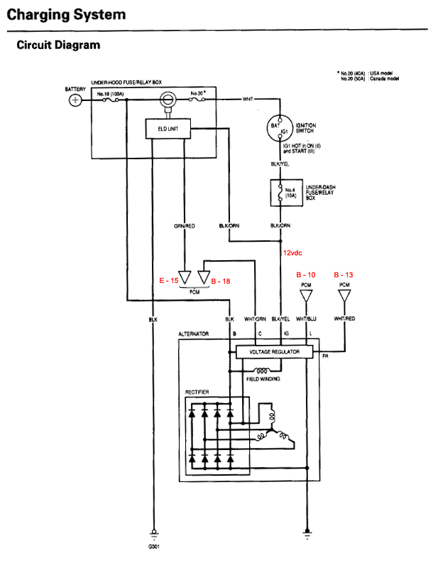
Terminals & Modes
The voltage regulator utilizes five terminals: Ignition (IG), Control (C), Field Reference (FR), Battery, (B) and Lamp (L). The B terminal is the high current circuit that's responsible for charging the battery. The other circuits are located in a single connector and are responsible for controlling the voltage regulator located within the alternator.
The IG circuit is crucial to proper charging system operation. Turning the ignition switch to the Run position will send source voltage to the IG terminal, which is required to energize the voltage regulator.
The C circuit is responsible for controlling the charge mode (based on the voltage on the ELD circuit). So indirectly, the ELD controls the charge rate (High/Low). The voltage regulator sends a voltage to the ECM through the C circuit. Depending on the charging systems needs, the ECM either holds the voltage high to signal the high output mode, or it pulls the voltage low to signal the low output mode. When the circuit C voltage is pulled low by the ECM: the charging voltage at the battery will range from 12.4 - 12.9V. The ECM uses the low output mode when the engine is starting or if all of the following parameters are met:
electrical Load below 15 Amps (varies with vehicle)
vehicle speed between 10-45 mph or at idle while in drive
engine speed below 3,000 rpm
coolant temperature above 167�F (75�C)
A/C Switch Off
intake air temperature above 68�F (20�C)
Outside of these parameters, the ECM will hold the voltage on the C circuit, which will place the charging system in the high output mode. In this mode, the charging voltage at the battery will range from 14.4-14.9V.
Note: The ELD circuit is pretty easy to fool. Pull the ELD out and use a 600-800 ohm resistor to ground and the ECM thinks the car's current load is high (forcing C to keep the alternator in high mode).
The ECM uses the FR circuit for field rotor status to be able to change engine idle speed. If the alternator is under high load, the ECM will increase idle speed. While the engine is running, the ECM sends 5V to the voltage regulator through the FR circuit. When the field rotor is on, the voltage regulator will pull the voltage down and when the field rotor is off it will hold the voltage high to around 6vdc.
The charging system utilizes the L circuit to inform the driver of any charging system faults. Over the years Honda has used two methods for illuminating the charge warning indicator lamp. On older models, the L circuit directly provided ground for the warning lamp if a problem was present. If everything was in spec, the voltage regulator removed the ground by providing positive source voltage on the L circuit.
However, on late model vehicles, the ECM sends source voltage to the L circuit. If a problem occurs, the voltage regulator will pull the voltage on the L circuit to ground. If this occurs, the ECM will sense that the signal voltage has been pulled down and it will then send a “charge warning lamp on” signal through the CAN bus network to the gauge control module. In this case, the gauge control module will directly switch the indicator lamp on.
My Troubleshooting Data
I fully charged the battery last night for some troubleshooting this morning. Here's what I have.
Test w/ ELD Resistor Removed - ELDv@ECM = 4.65v
Power On/Not Started/4P Connected to Alt
Measured@pins on ECU (All Connectors Connected)
C = 1.8v
FR = 5.1v
L = 1.3v
IG = 12.49v
AltL to Lamp (C101 pin 8) .03v
----------------------------------------------
4P Disconnected / Measurements at 4P Connector
C = -.08v
FR = 5.08v
L = .03v
IG = 12.49v
-------------------------------------------------
Reconnect 4P to Alt
Engine Started
Measured@pins on ECU (All Connectors Connected)
C = 1.32v
FR = 5.16v
L = 1.48v
IG = 12.37v
-----------------------------------------------------
Reinstall ELD Resistor to Ground
ELDv at ECU = 1.61
Engine Running
Measured@pins on ECU (All Connectors Connected)
C = 1.45v
FR = 5.15v
L = 1.7v
IG = 12.36v
I suspect the issue may be with the C circuit. Continuity checks okay and no shorts to ground. Disconnecting the C wire from the ECM and alternator has no effect on the charge voltage either. Still 12.30vdc with the C wire disconnected.
The manual does one additional test. With the 4p connector disconnected, start engine and measure voltage between +12v at battery and the C circuit pin on the 4p. I get 6-8v. I think the manual wanted to see less than 1v, suggesting I try a known good ECM.
An ECM is darned expensive to test with. Does anyone have another test that may provide conclusive direction? Bad ECM or multiple bad alternators?
Thanks,
Ken
Actually, I have a Lotus with a high performance K24, although the wiring harness and ECM are K20 (RSX Type S). The PRB ECU has been modified by Hondata. That said, all the charging system wiring is pure Honda (regardless of the Lotus chassis).
I'm going to dive a little deep here, but I'm trolling for someone who may have insight into my problem based on the troubleshooting data I've collected thus far.
ELD - Electrical Load Detector
The ECM outputs a 5vdc reference voltage to the ELD. The more load/current the ELD senses, the more it drops the 5vdc reference to ground. Between 1.5-2.5vdc, the ELD circuit will prompt the ECM to put the alternator in high charge mode (14vdc)
While I don't have an ELD, I did place a resistor on the ECM ELD 5v circuit to ground. Enough to drop the voltage to 1.5v (simulating high ELD load). Many guys with high wattage amps do this to prevent lights from flickering, etc.
Running at the high charge rate all the time is fine on the alternator. It just robs you of a little hp (like the old days).
Honda Charging System Wiring Diagram
Terminals & Modes
The voltage regulator utilizes five terminals: Ignition (IG), Control (C), Field Reference (FR), Battery, (B) and Lamp (L). The B terminal is the high current circuit that's responsible for charging the battery. The other circuits are located in a single connector and are responsible for controlling the voltage regulator located within the alternator.
The IG circuit is crucial to proper charging system operation. Turning the ignition switch to the Run position will send source voltage to the IG terminal, which is required to energize the voltage regulator.
The C circuit is responsible for controlling the charge mode (based on the voltage on the ELD circuit). So indirectly, the ELD controls the charge rate (High/Low). The voltage regulator sends a voltage to the ECM through the C circuit. Depending on the charging systems needs, the ECM either holds the voltage high to signal the high output mode, or it pulls the voltage low to signal the low output mode. When the circuit C voltage is pulled low by the ECM: the charging voltage at the battery will range from 12.4 - 12.9V. The ECM uses the low output mode when the engine is starting or if all of the following parameters are met:
electrical Load below 15 Amps (varies with vehicle)
vehicle speed between 10-45 mph or at idle while in drive
engine speed below 3,000 rpm
coolant temperature above 167�F (75�C)
A/C Switch Off
intake air temperature above 68�F (20�C)
Outside of these parameters, the ECM will hold the voltage on the C circuit, which will place the charging system in the high output mode. In this mode, the charging voltage at the battery will range from 14.4-14.9V.
Note: The ELD circuit is pretty easy to fool. Pull the ELD out and use a 600-800 ohm resistor to ground and the ECM thinks the car's current load is high (forcing C to keep the alternator in high mode).
The ECM uses the FR circuit for field rotor status to be able to change engine idle speed. If the alternator is under high load, the ECM will increase idle speed. While the engine is running, the ECM sends 5V to the voltage regulator through the FR circuit. When the field rotor is on, the voltage regulator will pull the voltage down and when the field rotor is off it will hold the voltage high to around 6vdc.
The charging system utilizes the L circuit to inform the driver of any charging system faults. Over the years Honda has used two methods for illuminating the charge warning indicator lamp. On older models, the L circuit directly provided ground for the warning lamp if a problem was present. If everything was in spec, the voltage regulator removed the ground by providing positive source voltage on the L circuit.
However, on late model vehicles, the ECM sends source voltage to the L circuit. If a problem occurs, the voltage regulator will pull the voltage on the L circuit to ground. If this occurs, the ECM will sense that the signal voltage has been pulled down and it will then send a “charge warning lamp on” signal through the CAN bus network to the gauge control module. In this case, the gauge control module will directly switch the indicator lamp on.
My Troubleshooting Data
I fully charged the battery last night for some troubleshooting this morning. Here's what I have.
Test w/ ELD Resistor Removed - ELDv@ECM = 4.65v
Power On/Not Started/4P Connected to Alt
Measured@pins on ECU (All Connectors Connected)
C = 1.8v
FR = 5.1v
L = 1.3v
IG = 12.49v
AltL to Lamp (C101 pin 8) .03v
----------------------------------------------
4P Disconnected / Measurements at 4P Connector
C = -.08v
FR = 5.08v
L = .03v
IG = 12.49v
-------------------------------------------------
Reconnect 4P to Alt
Engine Started
Measured@pins on ECU (All Connectors Connected)
C = 1.32v
FR = 5.16v
L = 1.48v
IG = 12.37v
-----------------------------------------------------
Reinstall ELD Resistor to Ground
ELDv at ECU = 1.61
Engine Running
Measured@pins on ECU (All Connectors Connected)
C = 1.45v
FR = 5.15v
L = 1.7v
IG = 12.36v
I suspect the issue may be with the C circuit. Continuity checks okay and no shorts to ground. Disconnecting the C wire from the ECM and alternator has no effect on the charge voltage either. Still 12.30vdc with the C wire disconnected.
The manual does one additional test. With the 4p connector disconnected, start engine and measure voltage between +12v at battery and the C circuit pin on the 4p. I get 6-8v. I think the manual wanted to see less than 1v, suggesting I try a known good ECM.
An ECM is darned expensive to test with. Does anyone have another test that may provide conclusive direction? Bad ECM or multiple bad alternators?
Thanks,
Ken

 04-21-2014, 09:50 AM
#3
Trial User
Thread Starter
Join Date: Apr 2014
Posts: 2
Likes: 0
Received 0 Likes
on
0 Posts
Thanks. I've had a sort of success this morning. I cleaned every ground and power connection (scuff with sandpaper and acetone). I disconnected both the ELD and AltC wires and I'm getting 14vdc+. I reconnected the AltC and it immediately dropped to 12vdc. I then disconnected the AltC again and re-started the car. Still 12vdc. Damn!
I shut everything down, disconnected the power at the battery, and let the ECM and Alt VR completely discharge of any mode of operation. I then disconnected the AltC again. 14vdc+!
I have restarted the car 10-15 times. 14vdc every time. I believe a faulty ECM is throwing the VR into a tizzy (via the AltC connection), so it shuts off. For now, I'll just leave it disconnected. Time will tell.

Thread
Thread Starter
Forum
Replies
Last Post