
oxygen sensor wire diagram
 03-12-2004, 06:17 PM
#1
Honda-Tech Member
Thread Starter
does anyone have the wiring diagram for an oxygen sensor 4 wire? the wires out of my sensor somehow got pulled out of the connector and im not sure which wire goes where.
 03-12-2004, 08:56 PM
#3
Member
Join Date: Jun 2003
Location: Somewhere in the lower part of, MI, U.S.A
Posts: 2,262
Likes: 0
Received 0 Likes
on
0 Posts
white wire is O2 Voltage (0-1V+), the 2 blacks need seperate grounds to most accurate, green need to be a swtiched 12V+ for the O2 heater 
03-13-2004, 05:57 PM
#5
Honda-Tech Member
Join Date: Dec 2001
Location: Gresham, Oregon, USA
Posts: 5,418
Likes: 0
Received 5 Likes
on
5 Posts
Made it a really long time ago and have posted it many times, hope it helps. Ignore all the VTEC stuff, I was basically just showing a conversion. Good Luck

EDITED... LINK UPDATED
Modified by Kataku2K3 at 10:34 PM 9/12/2006
EDITED... LINK UPDATED
Modified by Kataku2K3 at 10:34 PM 9/12/2006
03-13-2004, 07:59 PM
#7
Honda-Tech Member
Join Date: Dec 2001
Location: Gresham, Oregon, USA
Posts: 5,418
Likes: 0
Received 5 Likes
on
5 Posts
<TABLE WIDTH="90%" CELLSPACING=0 CELLPADDING=0 ALIGN=CENTER><TR><TD>Quote, originally posted by Sideout »</TD></TR><TR><TD CLASS="quote">white wire is O2 Voltage (0-1V+), the 2 blacks need seperate grounds to most accurate, green need to be a swtiched 12V+ for the O2 heater </TD></TR></TABLE>
That's only 1/4 of the way right. As my diagram shows you are correct in that the white is the reference output but the green is actually the ground for the entire sensor (ties into the TPS, ECT, IAT gnd.), while one of the blacks is a IGN 12V+ input for the oxygen sensor heater and the other is the ground trigger for the heater which is activated by the ECU.
</TD></TR></TABLE>That's only 1/4 of the way right. As my diagram shows you are correct in that the white is the reference output but the green is actually the ground for the entire sensor (ties into the TPS, ECT, IAT gnd.), while one of the blacks is a IGN 12V+ input for the oxygen sensor heater and the other is the ground trigger for the heater which is activated by the ECU.
Trending Topics
03-14-2004, 06:11 AM
#8
Honda-Tech Member
Thread Starter
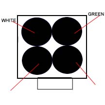
thats a great diagram, but i need it for the 4-wire oxygen sensor. i looked at my friends car yesterday on a lift and i saw that the top right is white the top left is green and the bottom two are black. which one is supposed to have the +12v? the bottom left or the bottom right? how can you check that the wires are properly connected? what will not having an oxygen sensor do besides making your car run richer?
03-14-2004, 09:31 AM
#9
Honda-Tech Member
ok here it is.
black wires are the heater element (you can hook them up either way)no directional polarity required
green is ground for the O2 sesnor
white is the signal
black wires are the heater element (you can hook them up either way)no directional polarity required
green is ground for the O2 sesnor
white is the signal
03-14-2004, 11:21 AM
#10
Honda-Tech Member
Thread Starter
k, can someone fill in the blanks on this and make sure the other 2 are right? thats what ive been trying to figure out.
http://ms0834.tripod.com/Untitled-2.jpg
Modified by IVI at 8:39 PM 3/14/2004
03-14-2004, 11:39 AM
#11
Honda-Tech Member
Join Date: Dec 2001
Location: Gresham, Oregon, USA
Posts: 5,418
Likes: 0
Received 5 Likes
on
5 Posts
As Qfactor said, polarity for the oxygen sensor heater really doesn't matter but if you want to wire it up the way the factory does, and the way I always do. The black wire on the left (of your diagram) is the IGN 12V+ and the one to the right is the ground trigger which traces back to the ECU (A6).
03-14-2004, 11:41 AM
#12
Honda-Tech Member
Thread Starter
okay thank you. so the wire on the left should have +12v? and the one of the right is just a ground? but they're both for the sensor heater? is the white/green on my diagram correct?
03-14-2004, 01:17 PM
#13
Honda-Tech Member
Join Date: Dec 2001
Location: Gresham, Oregon, USA
Posts: 5,418
Likes: 0
Received 5 Likes
on
5 Posts
Yea, you're diagram is fine and the one on the LEFT is a IGN 12V+ but the one on the <U>RIGHT</U> is not just any old ground, it has to trace back to pin A6 at the ECU (this way the ECU can regulate the heater). If you were to just ground the wire on the right to any old point your oxygen sensor heater would always be on (do NOT do this). Like we've said there really isn't any polarity so even if they are backwards it should still work but just to keep things organized I always do how I listed above. Good Luck
EDITED: because I wasn't thinking clearly...
Modified by Kataku2K3 at 7:19 PM 3/14/2004
EDITED: because I wasn't thinking clearly...
Modified by Kataku2K3 at 7:19 PM 3/14/2004
03-14-2004, 06:13 PM
#14
Honda-Tech Member
Thread Starter
<TABLE WIDTH="90%" CELLSPACING=0 CELLPADDING=0 ALIGN=CENTER><TR><TD>Quote, originally posted by Kataku2K3 »</TD></TR><TR><TD CLASS="quote">you're diagram is fine and the one on the LEFT is a IGN 12V+ but the one on the LEFT is not just any old ground</TD></TR></TABLE>do you mean the one on the RIGHT is not just any ground?
The following users liked this post:
03-25-2004, 07:21 AM
#17
Honda-Tech Member
Thread Starter
that diagram was actually not right. it was harder to do than i thought but i finally got it. ive made a diagram which is correct. here it is...
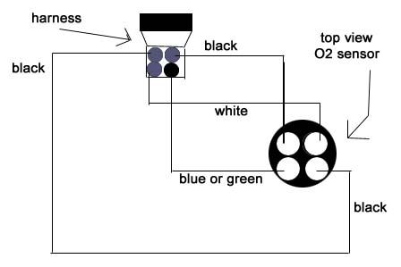
http://ms0834.tripod.com/o2wire.jpg
http://ms0834.tripod.com/o2wire.jpg
 03-27-2004, 04:47 AM
#20
Member
Join Date: Mar 2003
Location: Wrigleyville, IL
Posts: 1,230
Likes: 0
Received 0 Likes
on
0 Posts
The diagram above is for the actual o2 sensor side. Does any one have a diagram for the wire harness side. I need this pretty badly.

Thread
Thread Starter
Forum
Replies
Last Post
Powered By Garrett
Honda Civic / Del Sol (1992 - 2000)
4
02-17-2007 08:31 AM

