
Australian GSR
 08-17-2014, 10:51 PM
#51
Honda-Tech Member
Thread Starter
Join Date: Jun 2014
Location: Australia
Posts: 83
Likes: 0
Received 0 Likes
on
0 Posts
Thanks for all the kind words gents, I hope to keep the updates coming and I will definitely be backing the geeky stuff up with track time
 08-19-2014, 12:02 AM
#52
Honda-Tech Member
Thread Starter
Join Date: Jun 2014
Location: Australia
Posts: 83
Likes: 0
Received 0 Likes
on
0 Posts
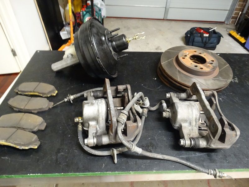
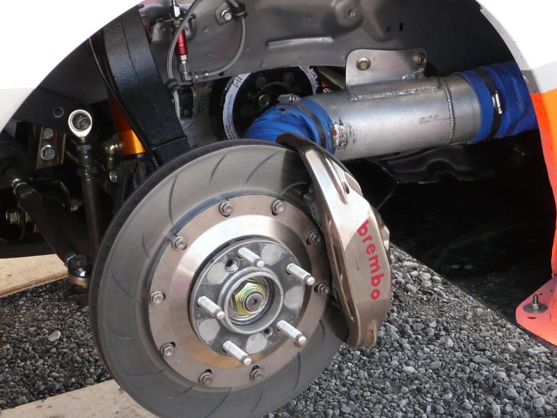
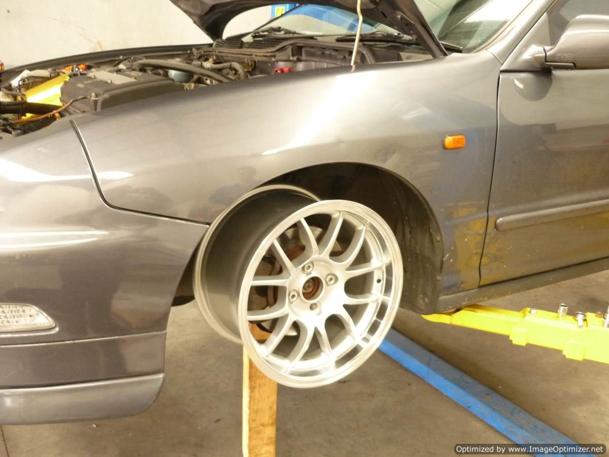
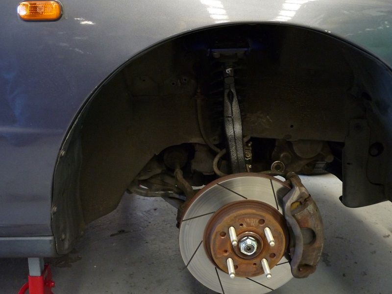
Quite by chance I came across a 4 x 100 brake upgrade for sale and decided it made sense to buy that rather than get new pads and rotors for the 262mm set up.
The calipers are DC2R and thats a 1" master cylinder
The rotors are 282mm slotted but I'm not sure what brand?
The kit came with EBC yellow pads with about 50% material left
The plan is to fit the big brakes when the new uprights go in.
The calipers are DC2R and thats a 1" master cylinder
The rotors are 282mm slotted but I'm not sure what brand?
The kit came with EBC yellow pads with about 50% material left
The plan is to fit the big brakes when the new uprights go in.
 08-19-2014, 04:46 PM
#53
Honda-Tech Member
I love seeing cleverly engineered track builds!, by chance are you an engineer by trade?. Are you planning on any aero parts(diffuser/splitter etc) I'd imagine you could fab up a crazy splitter judging by what I've seen so far. look forward to seeing more
08-19-2014, 07:07 PM
#54
Honda-Tech Member
Thread Starter
Join Date: Jun 2014
Location: Australia
Posts: 83
Likes: 0
Received 0 Likes
on
0 Posts
Ha yes I'm a Mechanical Engineer, also hopelessly obsessed with racecars.
I'm going to start with increasing the efficiency of the air flow through the front of the car by ducting the radiator and brakes but blocking off unnecessary open area.
Then I'm going to make a filler panel from the bottom of the rear bumper back to the rear subframe to smooth the air flow past the bumper. I don't think the diffusers that people tack under their cars can really work without a flat floor ahead of it, skirts etc.
Cutting the bumper back like you see some people do is just silly. Unnecessarily increases drag with no down force benefit
I'll probably mount an adjustable wing at the rear to try and reduce lift off overseer and when I fit that i'll probably fashion some kind of splitter to balance out the looks of the car. You won't see any riveted on carnards on this car.
I've got a plan to replace the plastic under tray at the front with an alloy/carbon version
I basically want to come up with an efficient package that keeps the cars balanced
08-20-2014, 02:41 PM
#55
Honda-Tech Member
I'm impressed, I was always trying to DIY my own aero but it never worked lol just had to get the "of the shelf stuff" in the end. I look forward to seeing what you make up for aero!.
08-26-2014, 01:57 AM
#56
Honda-Tech Member
Thread Starter
Join Date: Jun 2014
Location: Australia
Posts: 83
Likes: 0
Received 0 Likes
on
0 Posts
The rear sway bar started squeaking again at the end of last week so I dropped the bar on Saturday and re-applied thread tape to the areas that run inside the rubber bushes.
This gets rid of the squeaks for a few weeks.
You can see where the bar has been rotating in the bush
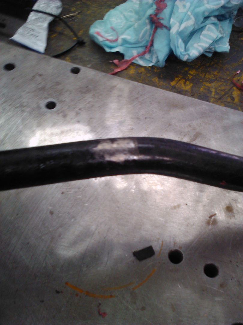
2-3 layers of thread tape around the offending area
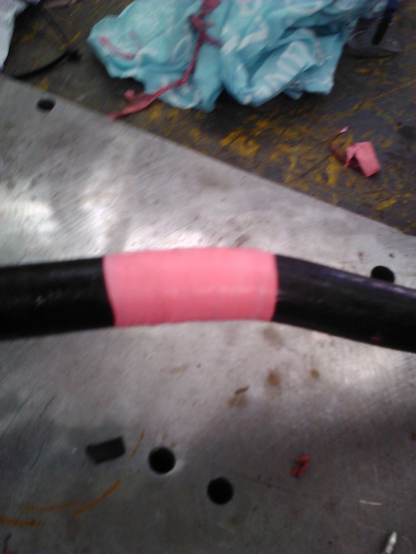
With no sound deadening left, these little jobs make the car easier to live with day to day.
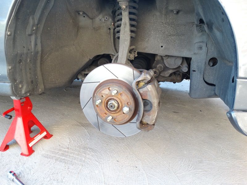
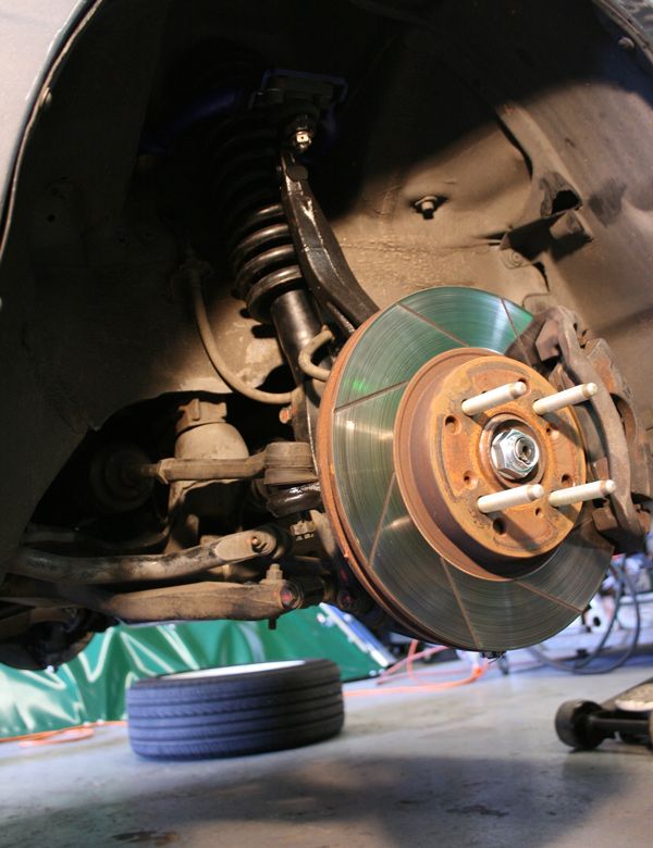
I also installed the bigger brakes on Sunday.
This gets rid of the squeaks for a few weeks.
You can see where the bar has been rotating in the bush

2-3 layers of thread tape around the offending area

With no sound deadening left, these little jobs make the car easier to live with day to day.
I also installed the bigger brakes on Sunday.
 08-30-2014, 12:24 AM
#57
Honda-Tech Member
Thread Starter
Join Date: Jun 2014
Location: Australia
Posts: 83
Likes: 0
Received 0 Likes
on
0 Posts
Ok, this is mostly a follow up to my previous post on bump steer but also may be of interest to those who were posting in Bazda's thread about bumpsteer.
The first you need to understand what we are trying to achieve. Our Honda's have a double wishbone front suspension and rack and pinion steering.
If you look at the image below, i have pulled a screen shot from Susprog 3d and overlayed some lines and annotations.
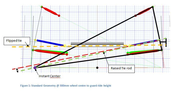
The way I visualize what is going on is to imagine that for this instance in time the thick black lines form a rigid member and the wheel pivots about the purple dot.
The purple dot indicates the instant centre, for every position of the wheel through its travel, this point is in a slightly different place
In theory, if the tie rod pointed at the instant centre, for all instant centre positions we would have no bumpsteer.
In the real world, the inner tie rod pivot is fixed relative to the chassis and the outer tie rod end point is fixed relative to the upright.
I'm not going to get into toe in vs toe out, slip angle etc in this post, rather just present the geometric implications of tie rod height on the upright.
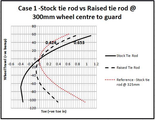
In the figure below I have plotted two toe curves for a Dc2 with a ride height equivalent of a car with 300mm distance from the centre of the wheel to the guard (CW2G).
The red dotted line is the toe curve with a ride height 325mm (WC2G) and is intended to show what a stock (slightly lowered) toe curve would look like.
The black dotted line is the toe curve for a tie rod end higher than stock and you can see raising the tie rod end has reduced the toe in with bump.
In these plots 0.2 deg roughly translates to 1mm of toe measured at the edge of the tyre for a 15" wheel.
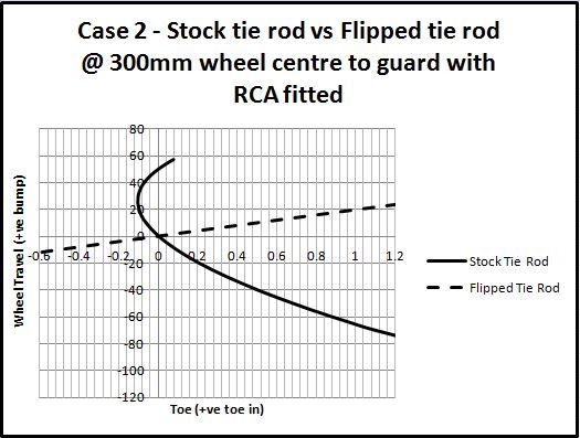
Case 2 is a dc2 with front roll centre adjusters fitted and with a ride height of 300mm (WC2G)
What is interesting in this case is that the wheel is toeing OUT with bump but the magnitude of toe change is rather small. This is why I suggest guys running RCA and stock tie rods arn't having any issues with bumpsteer.
The dotted line on this plot is the result of fitting a flipped tie rod (one that mounts underneath the steer arm). Oh dear, significant toe change with wheel position. This seems really extreme to me and I suspected something was wrong with the
model. I went over it a few times and always got a similar result. I'd be interested to see the results of someone running this set up measuring their bumpsteer with DTIs.
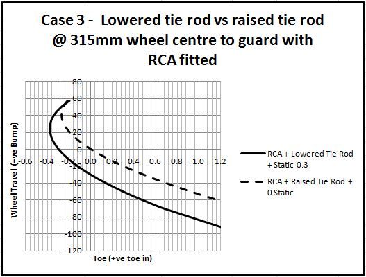
So if a car is running an RCA is their any benefit to modifying the tie rod height? I believe so.
Case 3 shows the two scenarios that I intend to test on track.
The sold line shows the toe curve that i believe is going to net the best laptimes, a lowered tie rod with static toe out.
The dotted line is an alternate set up where you run 0 toe out but raise the height of the tie rod.
Just to ground this discussion in the real world here is a picture of a height adjustable tie rod set up as used by the Real Time Racing Dc2
this car...
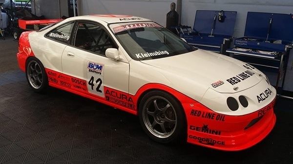
RTR images do not belong to me. Sourced from descartesfool on Honda-tech
Having worked out what I needed I did a bit of research and found no one makes such a thing.
I discussed the Tie Rod idea with another Honda owning engineer (ChargeR) at the Winton track day and he mentioned he had been planning to make something up himself so we decided to develop the tie rod kit together.
Those of you familiar with the stock tie rod will know it is curved to miss the back side of the wheel.
We didn't want to make our link curved but also wanted to prevent the possibility of the wheel rubbing on the tie rod.
We test fit a 15 x 9 +36 and took measurements to work out what kind of spacer would be required to reduce the rack travel and prevent wheel on tie rod contact.
We came up with a design for the spacer and organised to get the tie rod kit components produced.
The last of the components are due back from heat treat this week and I plan to get my set of tie rods installed at the same time I install the powdercoated uprights.
My apologies if any of the above is hard to read, I'm struggling with a severe case of man flu but wanted to get this posted as I said I would
The first you need to understand what we are trying to achieve. Our Honda's have a double wishbone front suspension and rack and pinion steering.
If you look at the image below, i have pulled a screen shot from Susprog 3d and overlayed some lines and annotations.

The way I visualize what is going on is to imagine that for this instance in time the thick black lines form a rigid member and the wheel pivots about the purple dot.
The purple dot indicates the instant centre, for every position of the wheel through its travel, this point is in a slightly different place
In theory, if the tie rod pointed at the instant centre, for all instant centre positions we would have no bumpsteer.
In the real world, the inner tie rod pivot is fixed relative to the chassis and the outer tie rod end point is fixed relative to the upright.
I'm not going to get into toe in vs toe out, slip angle etc in this post, rather just present the geometric implications of tie rod height on the upright.
In the figure below I have plotted two toe curves for a Dc2 with a ride height equivalent of a car with 300mm distance from the centre of the wheel to the guard (CW2G).
The red dotted line is the toe curve with a ride height 325mm (WC2G) and is intended to show what a stock (slightly lowered) toe curve would look like.
The black dotted line is the toe curve for a tie rod end higher than stock and you can see raising the tie rod end has reduced the toe in with bump.
In these plots 0.2 deg roughly translates to 1mm of toe measured at the edge of the tyre for a 15" wheel.

Case 2 is a dc2 with front roll centre adjusters fitted and with a ride height of 300mm (WC2G)
What is interesting in this case is that the wheel is toeing OUT with bump but the magnitude of toe change is rather small. This is why I suggest guys running RCA and stock tie rods arn't having any issues with bumpsteer.
The dotted line on this plot is the result of fitting a flipped tie rod (one that mounts underneath the steer arm). Oh dear, significant toe change with wheel position. This seems really extreme to me and I suspected something was wrong with the
model. I went over it a few times and always got a similar result. I'd be interested to see the results of someone running this set up measuring their bumpsteer with DTIs.

So if a car is running an RCA is their any benefit to modifying the tie rod height? I believe so.
Case 3 shows the two scenarios that I intend to test on track.
The sold line shows the toe curve that i believe is going to net the best laptimes, a lowered tie rod with static toe out.
The dotted line is an alternate set up where you run 0 toe out but raise the height of the tie rod.

Just to ground this discussion in the real world here is a picture of a height adjustable tie rod set up as used by the Real Time Racing Dc2

this car...

RTR images do not belong to me. Sourced from descartesfool on Honda-tech
Having worked out what I needed I did a bit of research and found no one makes such a thing.
I discussed the Tie Rod idea with another Honda owning engineer (ChargeR) at the Winton track day and he mentioned he had been planning to make something up himself so we decided to develop the tie rod kit together.

Those of you familiar with the stock tie rod will know it is curved to miss the back side of the wheel.
We didn't want to make our link curved but also wanted to prevent the possibility of the wheel rubbing on the tie rod.


We test fit a 15 x 9 +36 and took measurements to work out what kind of spacer would be required to reduce the rack travel and prevent wheel on tie rod contact.
We came up with a design for the spacer and organised to get the tie rod kit components produced.
The last of the components are due back from heat treat this week and I plan to get my set of tie rods installed at the same time I install the powdercoated uprights.
My apologies if any of the above is hard to read, I'm struggling with a severe case of man flu but wanted to get this posted as I said I would
08-30-2014, 01:59 AM
#58
Honda-Tech Member

Impressive work. With the addition of RCA on my gsr, I noticed a little more roll stiffness, but not much else.
The picture of the brake and suspension you posted appears to be a real time tsx, not dc2.
The picture of the brake and suspension you posted appears to be a real time tsx, not dc2.
09-07-2014, 03:41 AM
#59
Honda-Tech Member
Thread Starter
Join Date: Jun 2014
Location: Australia
Posts: 83
Likes: 0
Received 0 Likes
on
0 Posts
It has taken a lot longer than I anticipated to implement my "front and REAR roll centre corrected" set up, you really have to be patient and just roll with the punches when undertaking a novel project like this.
On Saturday I assembled the uprights with new OEM wheel bearings and fitted the J's Racing extended lower ball joints.
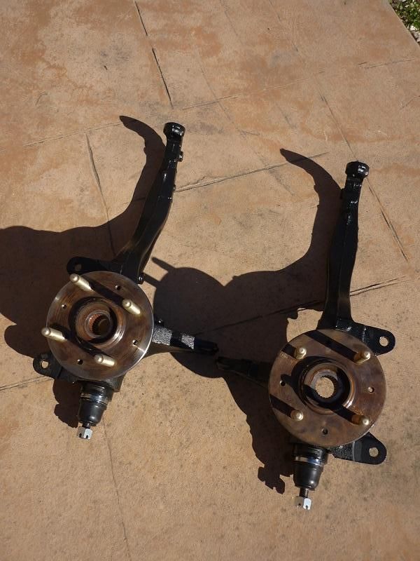
It took a bit of fluffing about in the press to get the ball joints installed but I managed to get them in eventually.
Today I set about installing the "new" uprights,
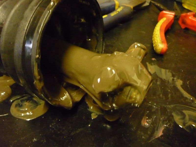
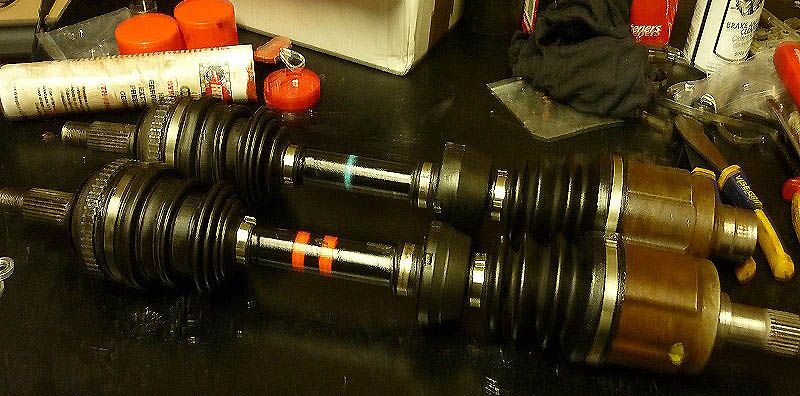
While I had the front end apart I took the opportunity to rebuild my axle shafts with Redline CV2 high temp grease.
Once I saw the condition of the old grease in my cvs I realised my axles were well overdue for a rebuild. This grease has lost all its viscosity and wouldn't be much chop to lubricate the cv

The completed axles, my apologies for the blurry photo, I brought the new stainless cv boot clips from ebay.
On Saturday I assembled the uprights with new OEM wheel bearings and fitted the J's Racing extended lower ball joints.

It took a bit of fluffing about in the press to get the ball joints installed but I managed to get them in eventually.
Today I set about installing the "new" uprights,
While I had the front end apart I took the opportunity to rebuild my axle shafts with Redline CV2 high temp grease.
Once I saw the condition of the old grease in my cvs I realised my axles were well overdue for a rebuild. This grease has lost all its viscosity and wouldn't be much chop to lubricate the cv


The completed axles, my apologies for the blurry photo, I brought the new stainless cv boot clips from ebay.
 09-15-2014, 03:47 AM
#60
Honda-Tech Member
Thread Starter
Join Date: Jun 2014
Location: Australia
Posts: 83
Likes: 0
Received 0 Likes
on
0 Posts
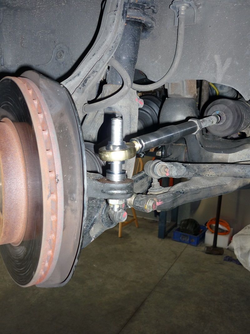
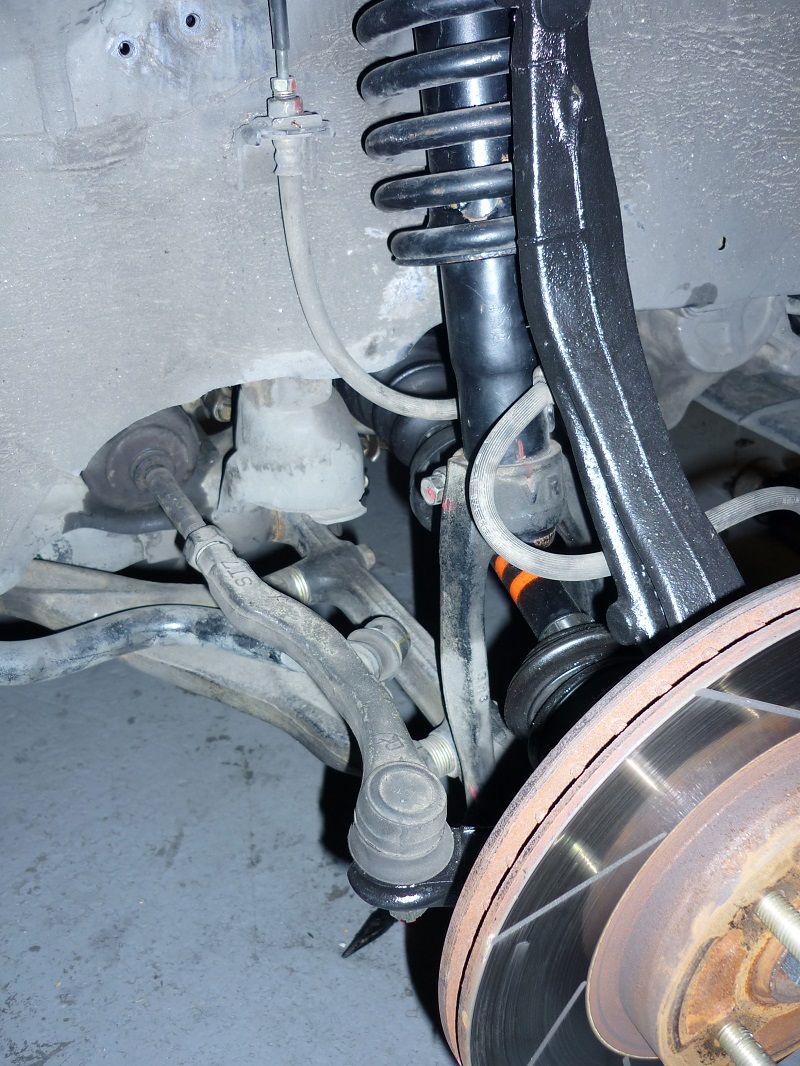
So I finally got the new front uprights with the extended ball joints installed.
Sunday was a pretty special day for me, after months of work it was finally time to install my adjustable tie rods.
If you look back though this thread you can read the explanation of why these came to exist but I haven't posted much of brunt that went into designing these bad boys.
Fair to say it was a bit of a journey and to say I was excited would be one hell of an understatement!
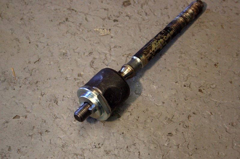
Take one standard tie rod end supplied on the car by Honda,
Throw that away and remove the inner tie rod end.
The original tie rod is curved to clear the back side of various wheel and tyre combinations, this is great if you're making 10's of 1000's of parts and can justify a forging die to make a stiff and strong curved part but
for a limited production run a straight turnbuckle is much more cost effective.
At the same time I want to be able to run wide rims and not have to stress about the tie rod contacting the rim on full lock
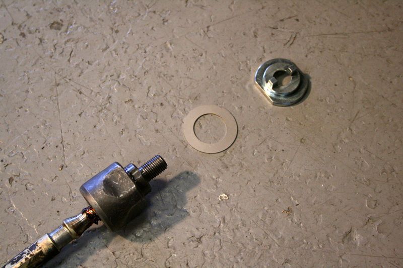
To solve this problem ChargeR (my partner in crime for this venture) and I came up with a rack end spacer that limits the lock just enough that a 15 x 9 +36 won't contact the tie rod (or the lower control arm)
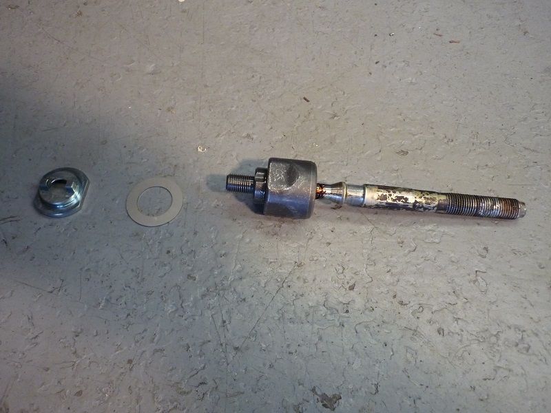
Lock limting spacer and locking washer shown above

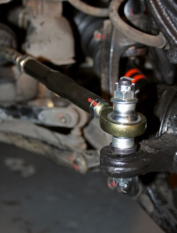
Once the inner rack end is re-installed it's a straight forward process of fitting a "stub" to the upright in place of the normal tie rod end. This stub has a taper to fit the taper of the upright and
above the taper a parallel shaft on which an Aurora 1/2" high misalignment rod end is fitted.
Because the shaft is parallel the height of the rod end can be adjusted with incremental spacers.
This allows me to adjust my tie rod end height to correct for my suspension geometry
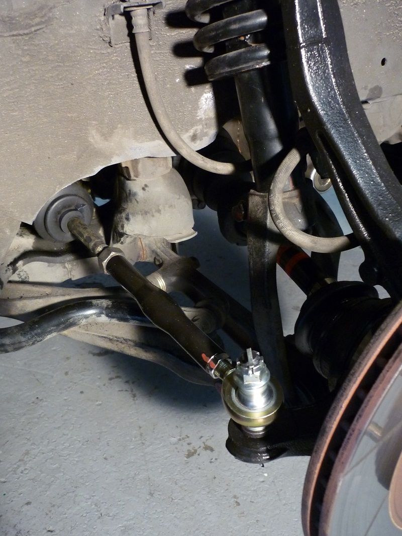
This car is running 3 degrees more castor than stock which rotates the upright back significantly. Rotating the upright back lowers the steering arm relative to the steering rack.
With this kit i can space the tie rod end up to correct for this and achieve the optimal bumpsteer characteristics!

Sunday was a pretty special day for me, after months of work it was finally time to install my adjustable tie rods.
If you look back though this thread you can read the explanation of why these came to exist but I haven't posted much of brunt that went into designing these bad boys.
Fair to say it was a bit of a journey and to say I was excited would be one hell of an understatement!
Take one standard tie rod end supplied on the car by Honda,

Throw that away and remove the inner tie rod end.
The original tie rod is curved to clear the back side of various wheel and tyre combinations, this is great if you're making 10's of 1000's of parts and can justify a forging die to make a stiff and strong curved part but
for a limited production run a straight turnbuckle is much more cost effective.
At the same time I want to be able to run wide rims and not have to stress about the tie rod contacting the rim on full lock
To solve this problem ChargeR (my partner in crime for this venture) and I came up with a rack end spacer that limits the lock just enough that a 15 x 9 +36 won't contact the tie rod (or the lower control arm)

Lock limting spacer and locking washer shown above

Once the inner rack end is re-installed it's a straight forward process of fitting a "stub" to the upright in place of the normal tie rod end. This stub has a taper to fit the taper of the upright and
above the taper a parallel shaft on which an Aurora 1/2" high misalignment rod end is fitted.
Because the shaft is parallel the height of the rod end can be adjusted with incremental spacers.
This allows me to adjust my tie rod end height to correct for my suspension geometry

This car is running 3 degrees more castor than stock which rotates the upright back significantly. Rotating the upright back lowers the steering arm relative to the steering rack.
With this kit i can space the tie rod end up to correct for this and achieve the optimal bumpsteer characteristics!
09-17-2014, 12:51 AM
#61
Honda-Tech Member
Thread Starter
Join Date: Jun 2014
Location: Australia
Posts: 83
Likes: 0
Received 0 Likes
on
0 Posts
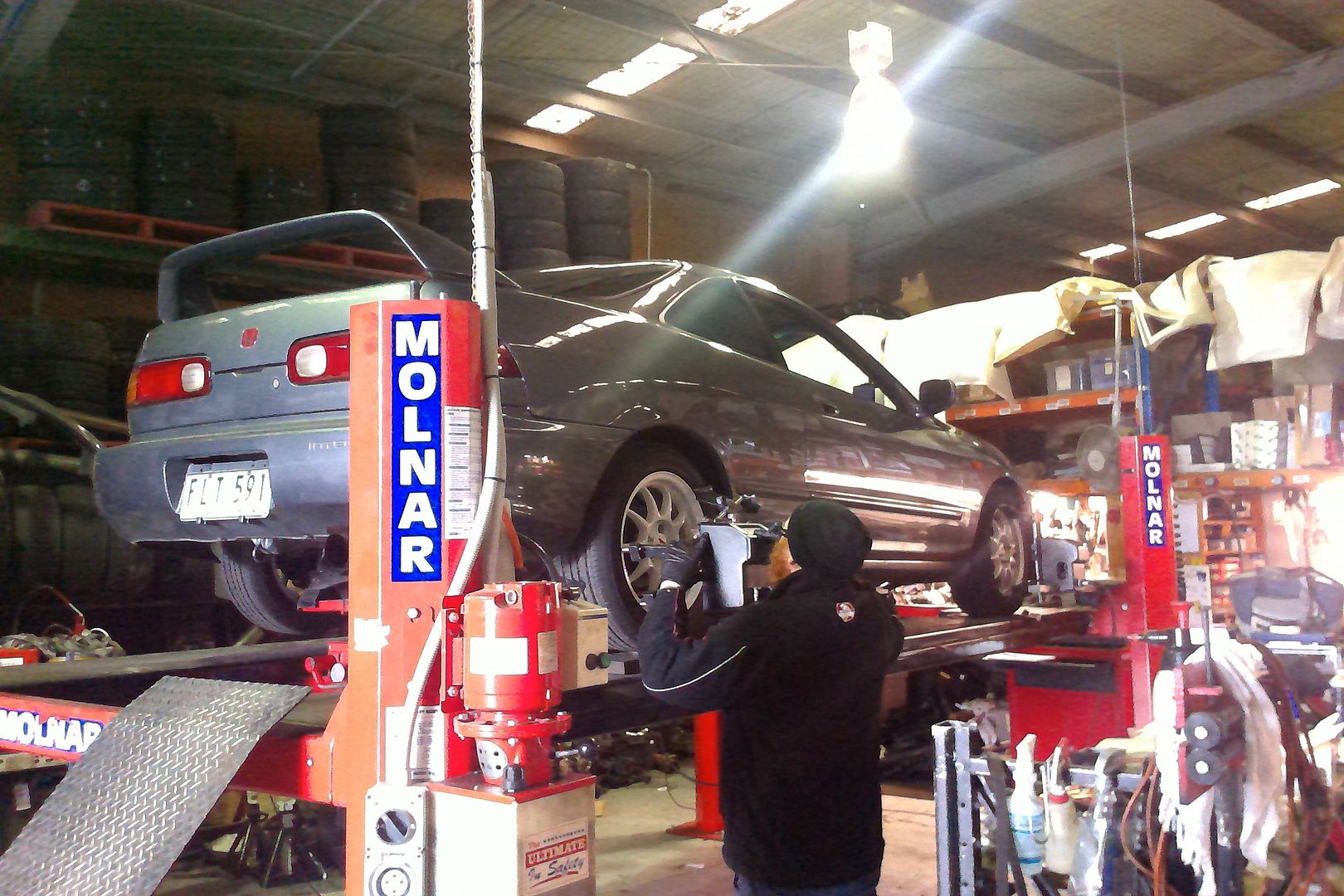
The car got dyno'd on Saturday,
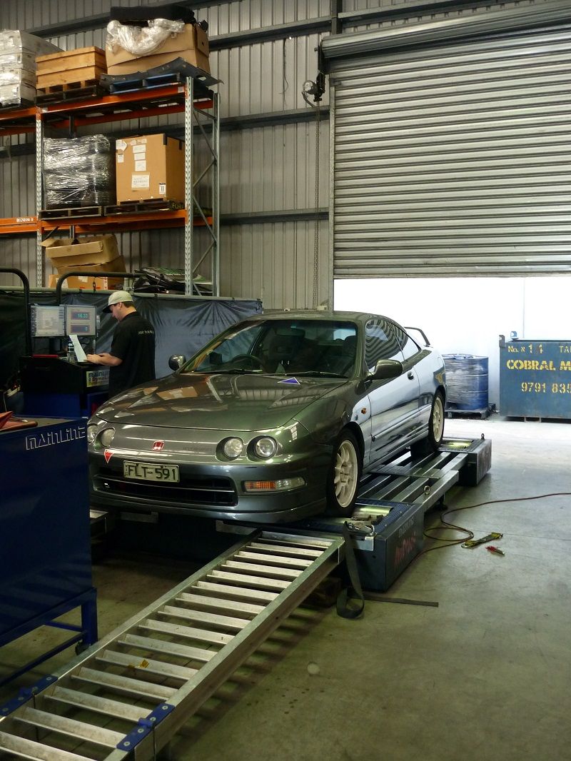
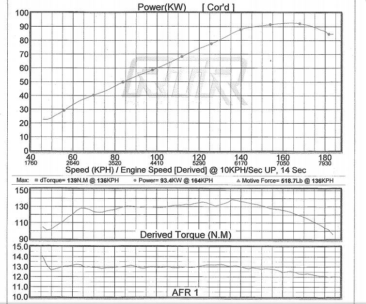
I've got no real plans to modify anything on the engine in the immediate future but it was good to get a base line for the car


I've got no real plans to modify anything on the engine in the immediate future but it was good to get a base line for the car
09-17-2014, 04:17 AM
#62
Honda-Tech Member
Thread Starter
Join Date: Jun 2014
Location: Australia
Posts: 83
Likes: 0
Received 0 Likes
on
0 Posts
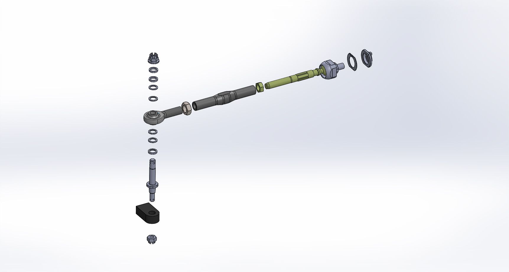
I've got some clearer photo's of the Tie Rod Kit
Original tie rod
Lock spacer assembled on the inner rack end. I've yet to notice an effective reduction in turning circle, I can still u-turn in a street (wideish one) no worries!
Nice shot of the components of the kit, you can see the stub on the left. These are made from 4140 then heat treated to 36 HRC.
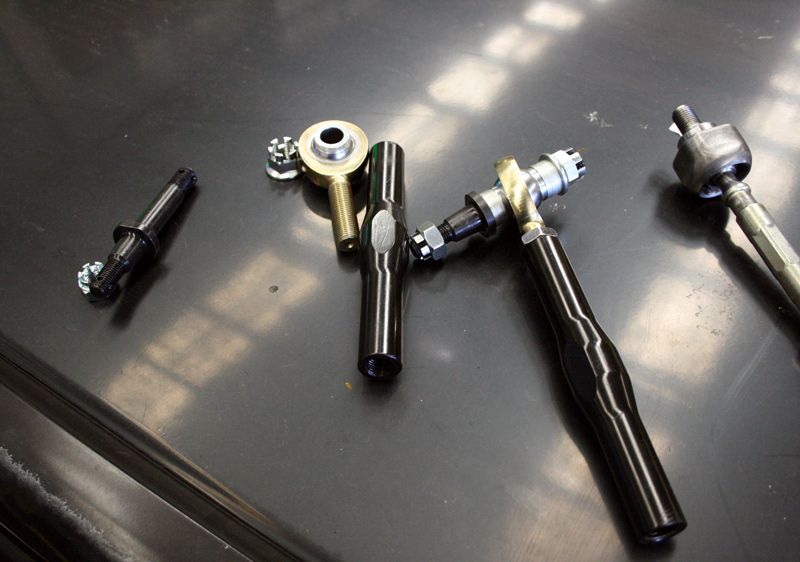
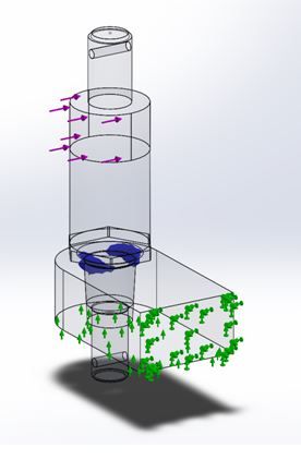
They stub was modelled in CAD, then analysed with SW simulation (FEA), to ensure it would be up to the task.
The turnbuckle, which is the bit that connects the rod end to the inner rack end, is also made from 4140
and to finish, a better image of the finished article, complete with paint marks.
The stub uses OEM tie rod and OEM ball joint castle nuts with split pins
Original tie rod


Lock spacer assembled on the inner rack end. I've yet to notice an effective reduction in turning circle, I can still u-turn in a street (wideish one) no worries!

Nice shot of the components of the kit, you can see the stub on the left. These are made from 4140 then heat treated to 36 HRC.

They stub was modelled in CAD, then analysed with SW simulation (FEA), to ensure it would be up to the task.

The turnbuckle, which is the bit that connects the rod end to the inner rack end, is also made from 4140
and to finish, a better image of the finished article, complete with paint marks.

The stub uses OEM tie rod and OEM ball joint castle nuts with split pins
09-17-2014, 04:18 AM
#63
Honda-Tech Member
Thread Starter
Join Date: Jun 2014
Location: Australia
Posts: 83
Likes: 0
Received 0 Likes
on
0 Posts
I've got some clearer photo's of the Tie Rod Kit
Original tie rod
Lock spacer assembled on the inner rack end. I've yet to notice an effective reduction in turning circle, I can still u-turn in a street (wideish one) no worries!
Nice shot of the components of the kit, you can see the stub on the left. These are made from 4140 then heat treated to 36 HRC.
The stub was modelled in CAD, then analysed with SW simulation (FEA), to ensure it would be up to the task.
The turnbuckle, which is the bit that connects the rod end to the inner rack end, is also made from 4140
and to finish, a better image of the finished article, complete with paint marks.
The stub uses OEM tie rod and OEM ball joint castle nuts with split pins
09-21-2014, 02:14 AM
#66
Honda-Tech Member
Thread Starter
Join Date: Jun 2014
Location: Australia
Posts: 83
Likes: 0
Received 0 Likes
on
0 Posts
I've mentioned a few times in this thread about an on going issue with the fuel pump cutting out. Unfortunately replacing the repco brand fuel pump with a walbro didn't fix the issue,
a few people mentioned that the fuel pump relay can fail and give similar problems so I decided to get my auto sparky flatmate to look at the relay.
Once he had the bottom of the dash apart he discovered the remains of an alarm system. Whoever installed the alarm had cut the the 12v feed for the fuel pump and spliced in a smaller gauge wire which t'd off to the alarm and then back to the fuel pump.
Needless to say we ripped all the wiring associated with the alarm out
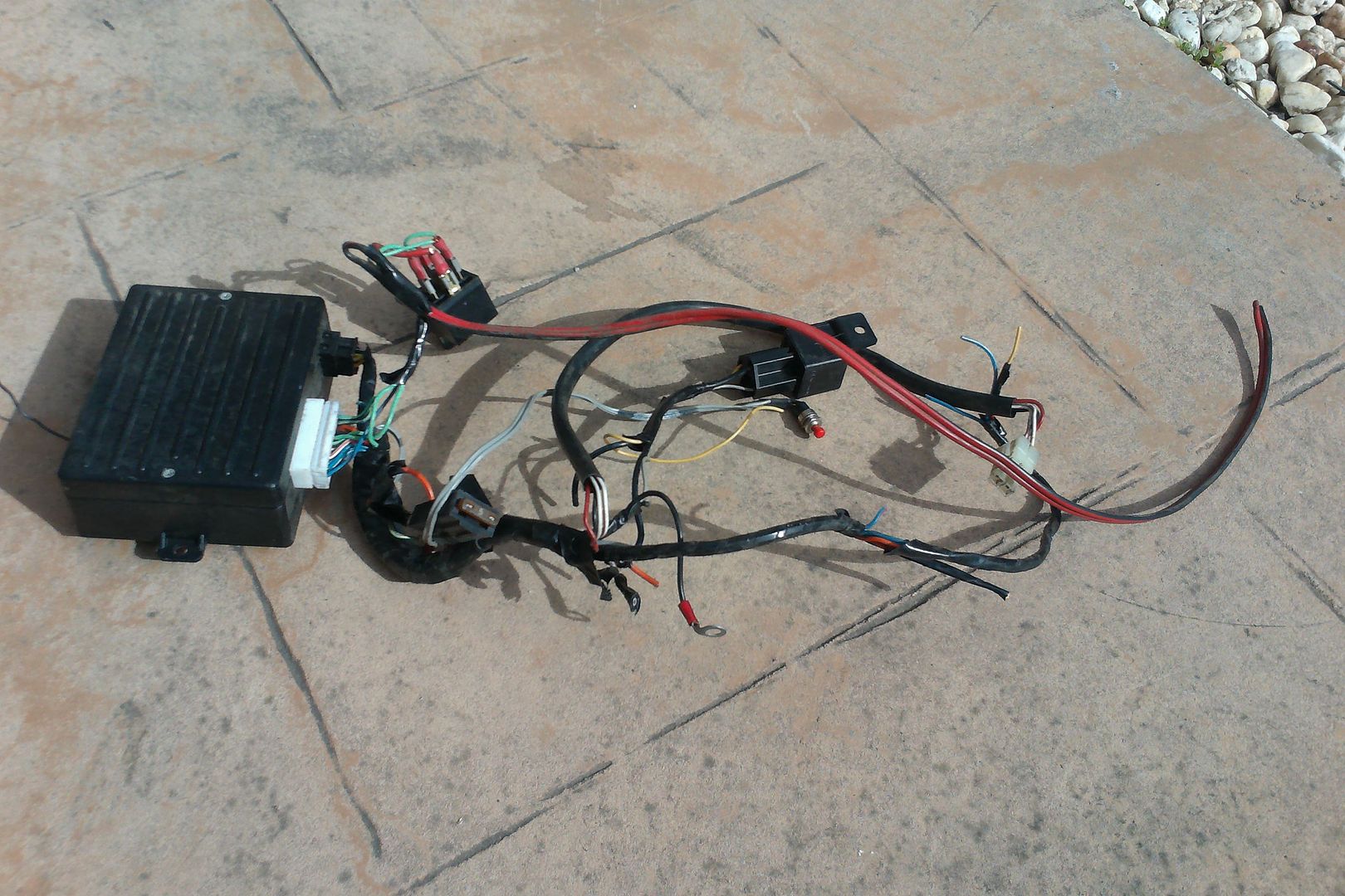
Martyn then replaced the OEM fuel pump relay and repaired the wiring.
While he was in there he removed the obnoxious "buzzer" that used to sound when you switched the ignition on, life is better now.
I booked the car in for a wheel alignment with techsport here in Melbourne. Now that this car's suspension is adjustable in almost every way I needed to find a shop that was willing to spend the time with me to get the car set up correctly.
Techsport's technician Zach was great in this regard, I think we spent almost 2 hours aligning the car and Zach didn't flinch when I asked him to drop the rear toe arms so that we could get them equal length on each side.
When I installed the new uprights I swapped the upper control arms from right to left which increased the castor (thanks coupe-R)
The car is now running 3.5 deg castor at the front and this was immediately noticeable.
My buddy ChargeR from the Australian forums entered his EF in an Alfa Romeo track day due to be held on Sunday at the Sandown raceway in Melbourne but due to unforeseen circumstance his EF was unable to run the event.
I suggested that we enter my car and take turns driving it, he agreed and we contacted the organisers and got the entry modified.
In addition to helping ChargeR get the track time he paid for, I really wanted to have someone drive my car and give me some feedback on the handling.
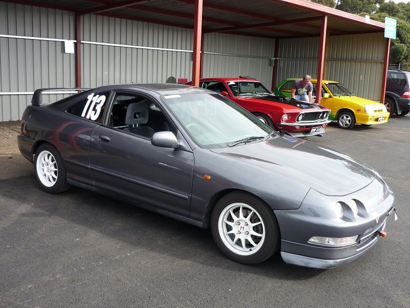
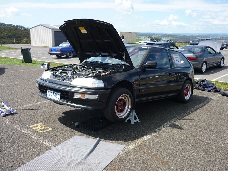
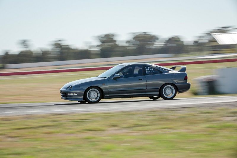
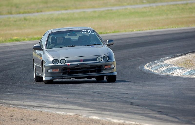
here she is all ready to go
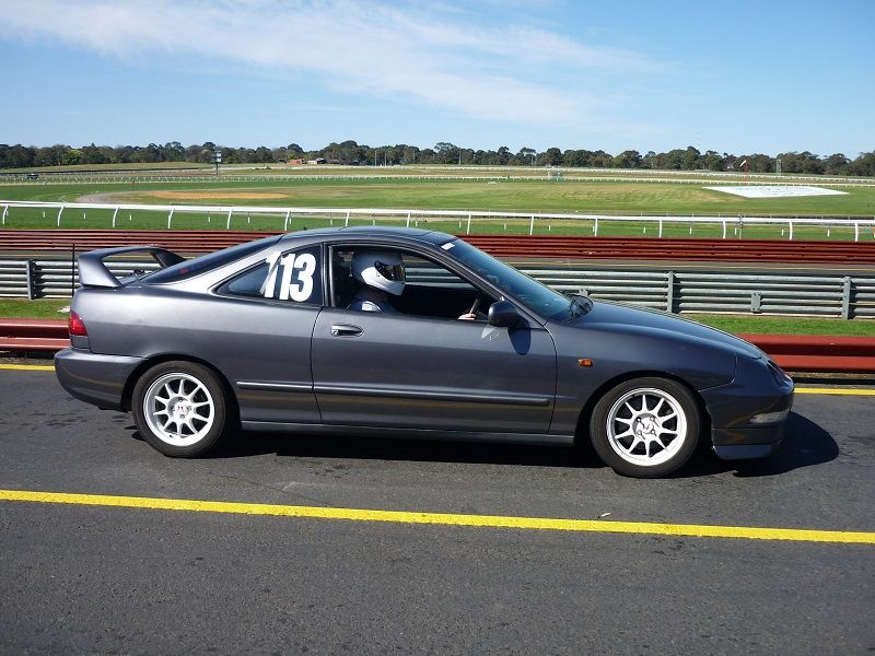
here's ChargeR on the grid ready to go out
The car performed faultlessly all day, the car ended up doing something like eight sessions out on track and other than adding a bit of oil at lunch time we didn't have to touch it.
I pb'd with a 1.35.4 in my first session, but only achieved a 37 in the second session and 36's in the third.
At the end of my second timed session a young guy put his Alfa into the Armco and about 120km'hr and damaged the armco enough that the rest of the day was run with a permanent yellow flag through that section.
This ment we were having to lift off though one of the fastest parts of the track, I'm sure I was putting together better laps in that final session but unfortunately with the yellow flag the times don't reflect the improvement.
a few people mentioned that the fuel pump relay can fail and give similar problems so I decided to get my auto sparky flatmate to look at the relay.
Once he had the bottom of the dash apart he discovered the remains of an alarm system. Whoever installed the alarm had cut the the 12v feed for the fuel pump and spliced in a smaller gauge wire which t'd off to the alarm and then back to the fuel pump.
Needless to say we ripped all the wiring associated with the alarm out

Martyn then replaced the OEM fuel pump relay and repaired the wiring.
While he was in there he removed the obnoxious "buzzer" that used to sound when you switched the ignition on, life is better now.
I booked the car in for a wheel alignment with techsport here in Melbourne. Now that this car's suspension is adjustable in almost every way I needed to find a shop that was willing to spend the time with me to get the car set up correctly.
Techsport's technician Zach was great in this regard, I think we spent almost 2 hours aligning the car and Zach didn't flinch when I asked him to drop the rear toe arms so that we could get them equal length on each side.

When I installed the new uprights I swapped the upper control arms from right to left which increased the castor (thanks coupe-R)
The car is now running 3.5 deg castor at the front and this was immediately noticeable.
My buddy ChargeR from the Australian forums entered his EF in an Alfa Romeo track day due to be held on Sunday at the Sandown raceway in Melbourne but due to unforeseen circumstance his EF was unable to run the event.
I suggested that we enter my car and take turns driving it, he agreed and we contacted the organisers and got the entry modified.
In addition to helping ChargeR get the track time he paid for, I really wanted to have someone drive my car and give me some feedback on the handling.
here she is all ready to go

here's ChargeR on the grid ready to go out

The car performed faultlessly all day, the car ended up doing something like eight sessions out on track and other than adding a bit of oil at lunch time we didn't have to touch it.
I pb'd with a 1.35.4 in my first session, but only achieved a 37 in the second session and 36's in the third.
At the end of my second timed session a young guy put his Alfa into the Armco and about 120km'hr and damaged the armco enough that the rest of the day was run with a permanent yellow flag through that section.
This ment we were having to lift off though one of the fastest parts of the track, I'm sure I was putting together better laps in that final session but unfortunately with the yellow flag the times don't reflect the improvement.
09-21-2014, 01:55 PM
#67
Honda-Tech Member
Thread Starter
Join Date: Jun 2014
Location: Australia
Posts: 83
Likes: 0
Received 0 Likes
on
0 Posts
Here's ChargeR's thoughts on the car:
My thoughts from the day:
- Maybe it's because your car has much more reasonable scrub radius than my car, but I found your car very directionally stable under brakes compared to mine.
- It was very easy to adjust the attitude of the car during the corner with the throttle, and oversteer was nice and progressive. Car changed direction well given that it's pretty softly sprung.
- I need to make a taller shifter for my car, but you need a seat and a steering wheel
He didnt get to drive the car on track before the modifications but he's driven enough fwd track cars to judge its qualities.
09-29-2014, 02:46 AM
#68
Honda-Tech Member
Thread Starter
Join Date: Jun 2014
Location: Australia
Posts: 83
Likes: 0
Received 0 Likes
on
0 Posts
ven though the car performed faultlessly at Sandown last weekend, I was a bit anxious about the car's condition
My last car was a BMW e30 and I had the worst run with that car, snapped timing belt, headgasket, water pump failure etc etc.
I think that experience has made me terminally suspicious of cars
Monday and Tuesday after work I put the car up on jack stands pulled all the wheels off and gave the car a thorough post event check over
- All the bolts were still tight
- Tie Rods looked fine
- LHS inner Cv boot was leaking slightly
I fixed the CV boot with a new band clamp, topped up the water and oil and parked it up ready to drive down to Haunted Hills on Saturday morning.
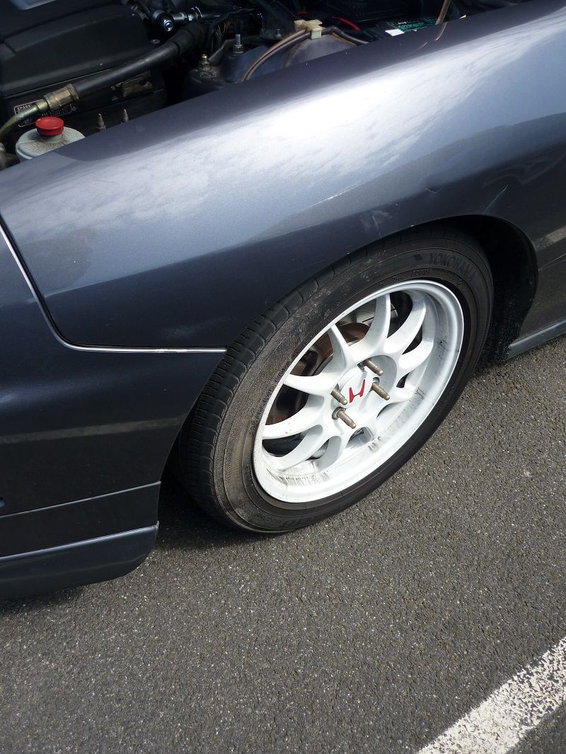
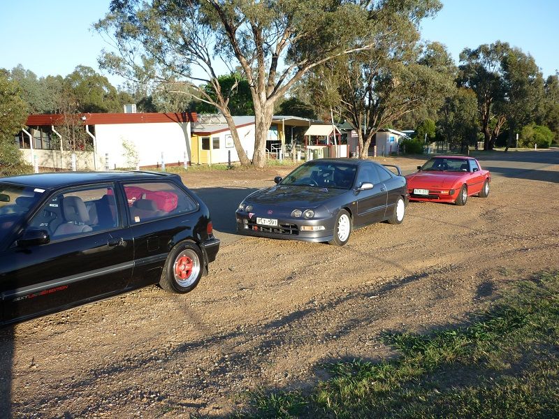
Saturday morning rolled around and I met up with ChargeR in his EF and we made our way down to the Haunted Hills track
I think the carpark we met up in had freshly painted lines on the pavement marking out the carparks. Somehow my tyres ended up covered in white paint, not the best start to the day.
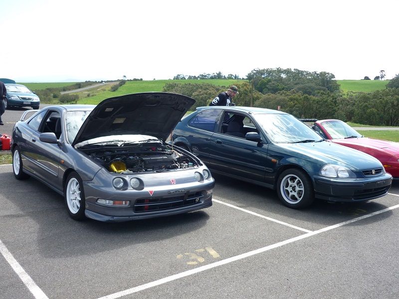
Here's the car parked up in the pits next to Rhys's EK. I ended up following Rhys in the run order
Second run of the day was interrupted with a spin at the third corner. Cause of the spin was driver error, I down shifted pretty much in the corner and the **** end looped around on me.
I was relieved that the car spun to the inside of the bend, which is a relatively flat bit of grass. The outside of that bend in notorious for turning cars on their lids!
On the drive down, ChargeR's EF suddenly "got a bit louder". As it turns out one of the surplus plugs in his header had vibrated loose. We attempted to plug the hole with
what we had lying around but we couldn't get a fix to stay in place.
You'd think this would have slowed him down but he still went faster than me with 50kw less, to quote MacGillz "he has no fear"
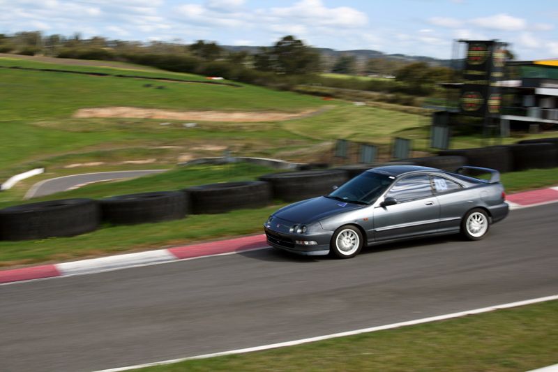
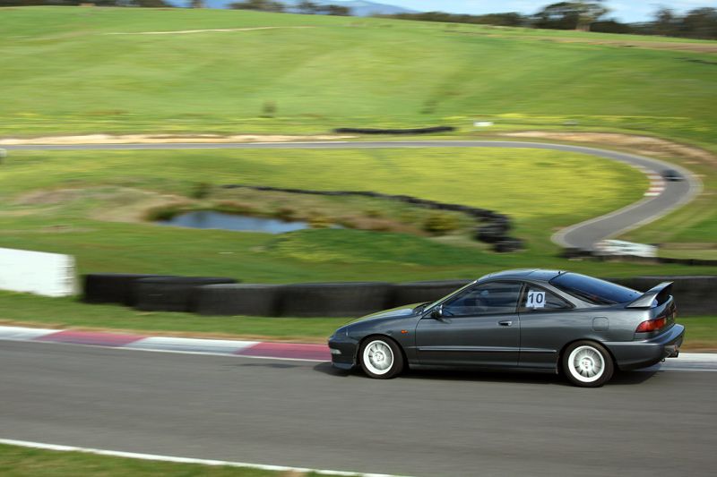
Couple of action shots thanks to ChargeR's nice camera
I think my best time was a 63.3 or something like that.
I found the car handled the course better than the first time I was at HH but we we're running a different configuration for this event so I can't directly compare the times.
Next event is Winton raceway on the 12th of October
My last car was a BMW e30 and I had the worst run with that car, snapped timing belt, headgasket, water pump failure etc etc.
I think that experience has made me terminally suspicious of cars
Monday and Tuesday after work I put the car up on jack stands pulled all the wheels off and gave the car a thorough post event check over
- All the bolts were still tight
- Tie Rods looked fine
- LHS inner Cv boot was leaking slightly
I fixed the CV boot with a new band clamp, topped up the water and oil and parked it up ready to drive down to Haunted Hills on Saturday morning.
Saturday morning rolled around and I met up with ChargeR in his EF and we made our way down to the Haunted Hills track

I think the carpark we met up in had freshly painted lines on the pavement marking out the carparks. Somehow my tyres ended up covered in white paint, not the best start to the day.

Here's the car parked up in the pits next to Rhys's EK. I ended up following Rhys in the run order

Second run of the day was interrupted with a spin at the third corner. Cause of the spin was driver error, I down shifted pretty much in the corner and the **** end looped around on me.

I was relieved that the car spun to the inside of the bend, which is a relatively flat bit of grass. The outside of that bend in notorious for turning cars on their lids!
On the drive down, ChargeR's EF suddenly "got a bit louder". As it turns out one of the surplus plugs in his header had vibrated loose. We attempted to plug the hole with
what we had lying around but we couldn't get a fix to stay in place.
You'd think this would have slowed him down but he still went faster than me with 50kw less, to quote MacGillz "he has no fear"

Couple of action shots thanks to ChargeR's nice camera


I think my best time was a 63.3 or something like that.
I found the car handled the course better than the first time I was at HH but we we're running a different configuration for this event so I can't directly compare the times.
Next event is Winton raceway on the 12th of October
10-20-2014, 01:40 AM
#69
Honda-Tech Member
Thread Starter
Join Date: Jun 2014
Location: Australia
Posts: 83
Likes: 0
Received 0 Likes
on
0 Posts
Hi All,
I took the back to Winton on the 12th and managed a 1.48.7 which is a 2 second improvement over the time I achieved back in June.
The car has been running strong and I felt reasonably confident driving it the 3 hours to Benella, the closest town to Winton, the night before. I was very grateful to have a couch to sleep on!
Since we drove up the night before we got to the track before the gates opened.
The day started out with near ideal conditions but as the sun rose the ambient and track temp soared.
I set my fastest time in my second session for the day and it seemed that most people were the same.
In my third session I found myself "over driving" the car trying to ekk every little bit out of the tyres, it felt faster in the cabin but didn't show in the times.
I went for a passenger ride in an ED with Hankook RS3s and was very impressed with the level of grip! I think new tyres will be the next upgrade.
I took the back to Winton on the 12th and managed a 1.48.7 which is a 2 second improvement over the time I achieved back in June.
The car has been running strong and I felt reasonably confident driving it the 3 hours to Benella, the closest town to Winton, the night before. I was very grateful to have a couch to sleep on!
Since we drove up the night before we got to the track before the gates opened.

The day started out with near ideal conditions but as the sun rose the ambient and track temp soared.

I set my fastest time in my second session for the day and it seemed that most people were the same.

In my third session I found myself "over driving" the car trying to ekk every little bit out of the tyres, it felt faster in the cabin but didn't show in the times.
I went for a passenger ride in an ED with Hankook RS3s and was very impressed with the level of grip! I think new tyres will be the next upgrade.
10-25-2014, 09:06 PM
#70
Honda-Tech Member
Thread Starter
Join Date: Jun 2014
Location: Australia
Posts: 83
Likes: 0
Received 0 Likes
on
0 Posts
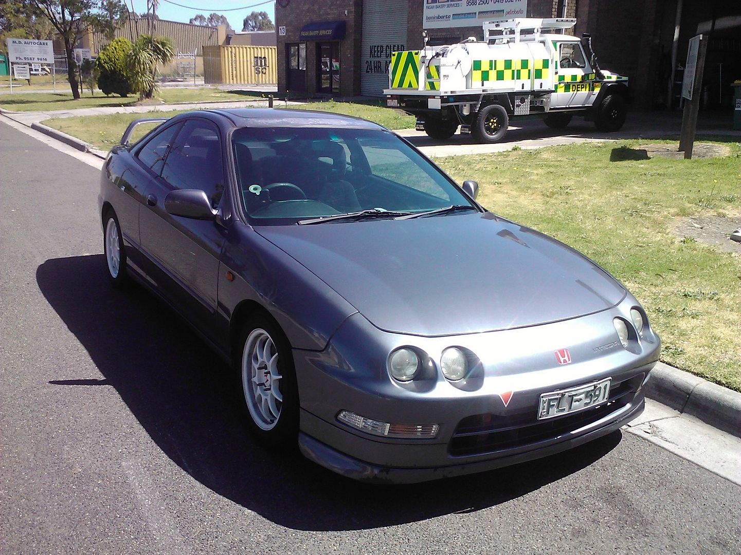
This weekends progress..
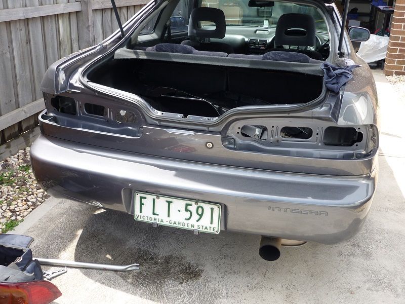
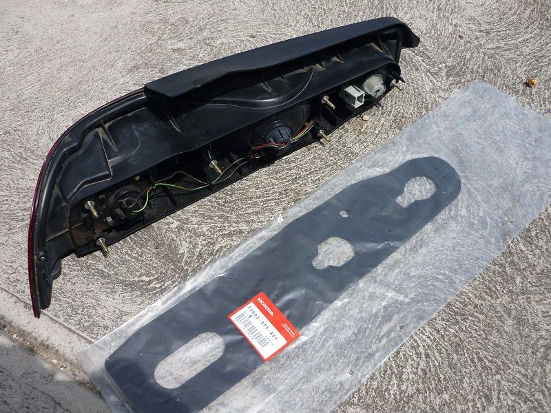
All winter the car has been filling the spare wheel well with water, I thought it was a blocked sunroof drain tube but even after I removed the sunroof and all the drain tubes it kept happening.
Then I noticed the tail lights had minor condensation inside the lenses, so I ordered a set of OEM tail light seals and procedure'd a new set of bulbs
Today i got around to replacing the seals and bulbs. I gave the seams a good clean all around the back of the car
I'm still undecided what the future holds in terms of the power plant but regardless of what I end up doing I want to run an electric power steering pump.
I went to the local wreckers and picked up an Astra hydroelectric powersteering unit. I prefer this unit to the mr2 because it has an integrated reservoir.
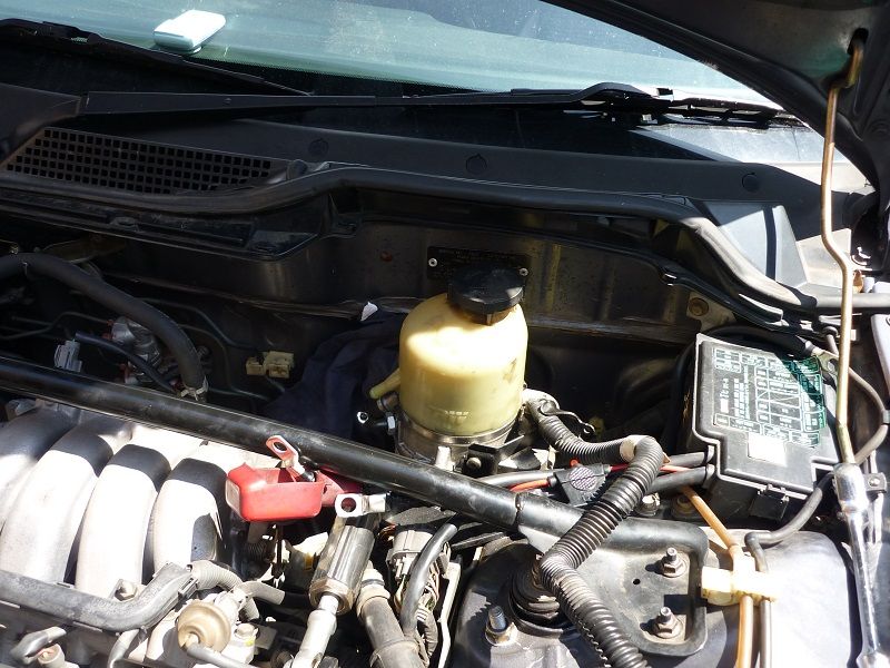
I'm going to relocated the standard battery to the boot for now but i'll eventually mount a nice dry cell above the fuel tank.
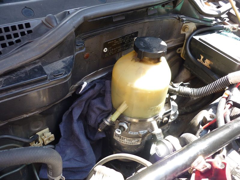
You can see the astra pump is a nice fit in the battery's original position.
I have worked out my hydraulic line routing and will get the lines made up this week; I've got the adapter fittings on the way out from summit.
Another small project but it should make things easier in the future.
All winter the car has been filling the spare wheel well with water, I thought it was a blocked sunroof drain tube but even after I removed the sunroof and all the drain tubes it kept happening.
Then I noticed the tail lights had minor condensation inside the lenses, so I ordered a set of OEM tail light seals and procedure'd a new set of bulbs
Today i got around to replacing the seals and bulbs. I gave the seams a good clean all around the back of the car


I'm still undecided what the future holds in terms of the power plant but regardless of what I end up doing I want to run an electric power steering pump.
I went to the local wreckers and picked up an Astra hydroelectric powersteering unit. I prefer this unit to the mr2 because it has an integrated reservoir.

I'm going to relocated the standard battery to the boot for now but i'll eventually mount a nice dry cell above the fuel tank.

You can see the astra pump is a nice fit in the battery's original position.
I have worked out my hydraulic line routing and will get the lines made up this week; I've got the adapter fittings on the way out from summit.
Another small project but it should make things easier in the future.
11-08-2014, 08:25 PM
#71
Honda-Tech Member
Thread Starter
Join Date: Jun 2014
Location: Australia
Posts: 83
Likes: 0
Received 0 Likes
on
0 Posts
Hi All,
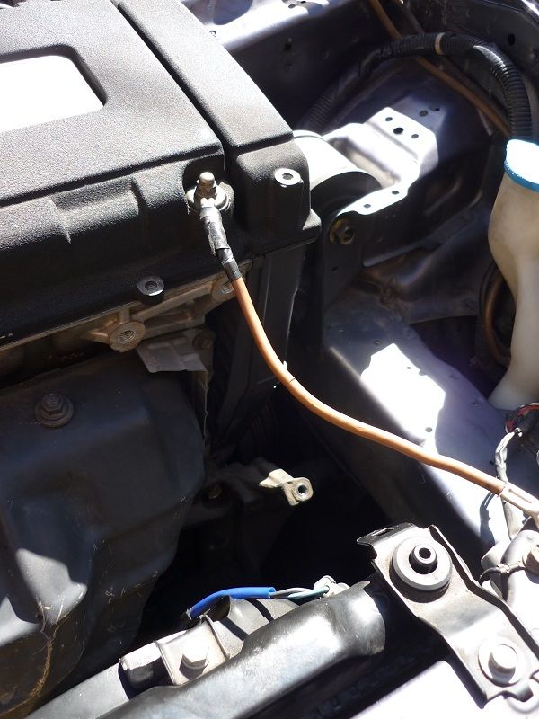
This week I completed the electric power steering pump installation.
I went back to the pick-a-part and collected a second DC2 battery tray, this was then modified to mount the battery in the boot.
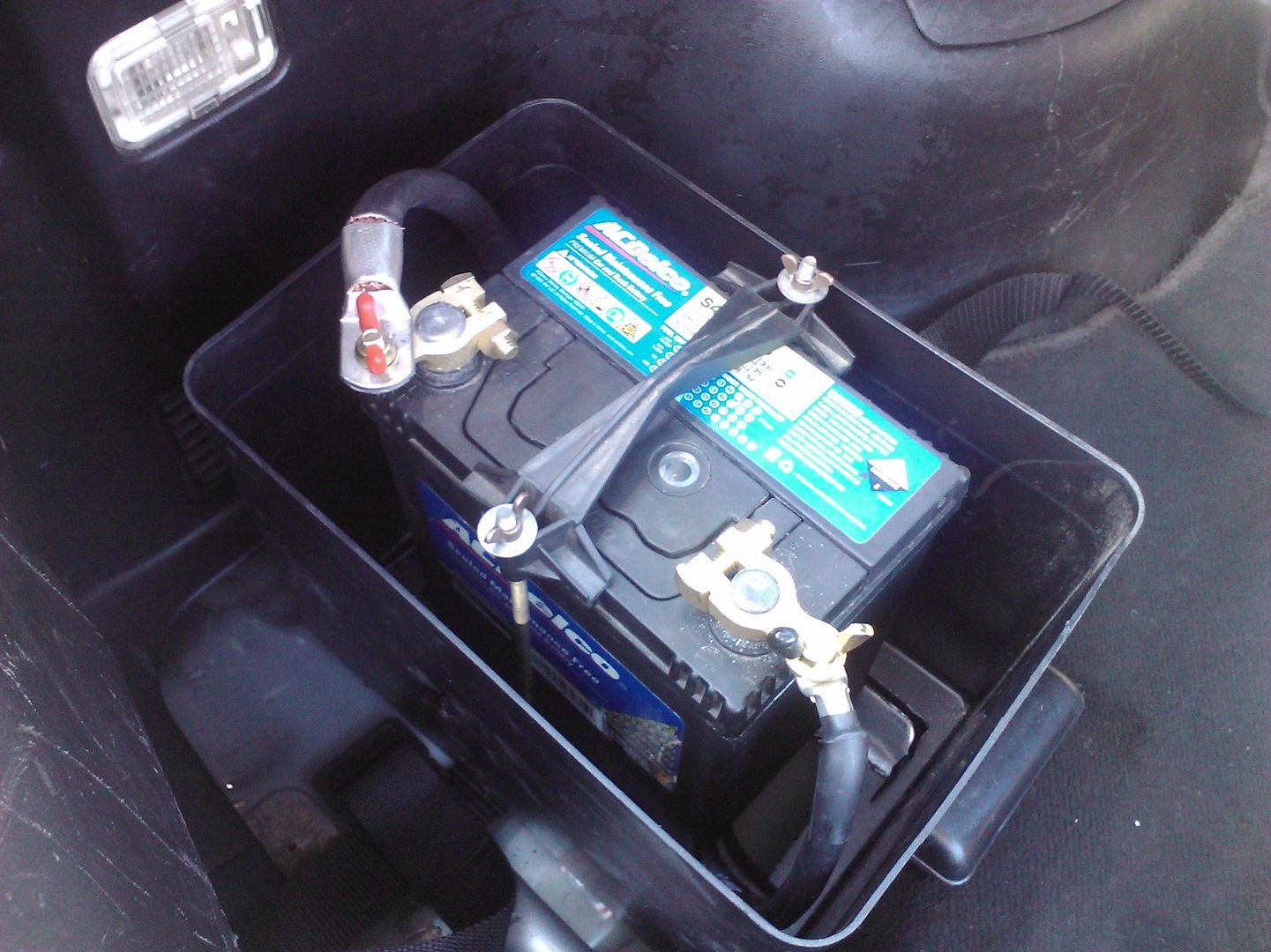
This worked out well as it allowed me to re-use the original clamp and the battery is very secure. I will revisit the box sometime in the future, i ended up cutting most of the bottom out of it, so much so that it's not really "Sealed"
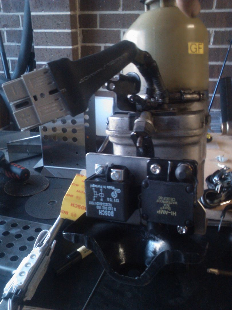
Pump in it's final resting place. The pump has it's own mounting bracket which I wanted to re-use so the pump is isolated on its oem rubber mounts. All we did was notch the battery tray to suit the astra bracket and then weld the two together.
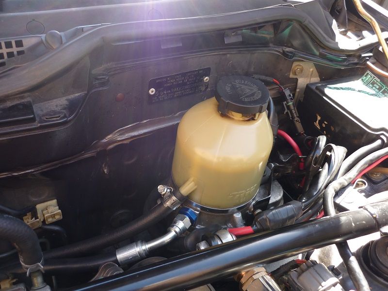
Here you can see the relay and circuit breaker mounted off the modified battery tray.
All the auxiliary's have now been removed or replaced off the front of the engine. Regardless of what I end up doing with the engine, not having to worry about power steering is a bonus
The parts that were removed, my driveway is covered in power steering fluid! a warning to anyone thinking of doing this in the future, prepare to get covered in power steering fluid! This would have been much easier with the engine removed.
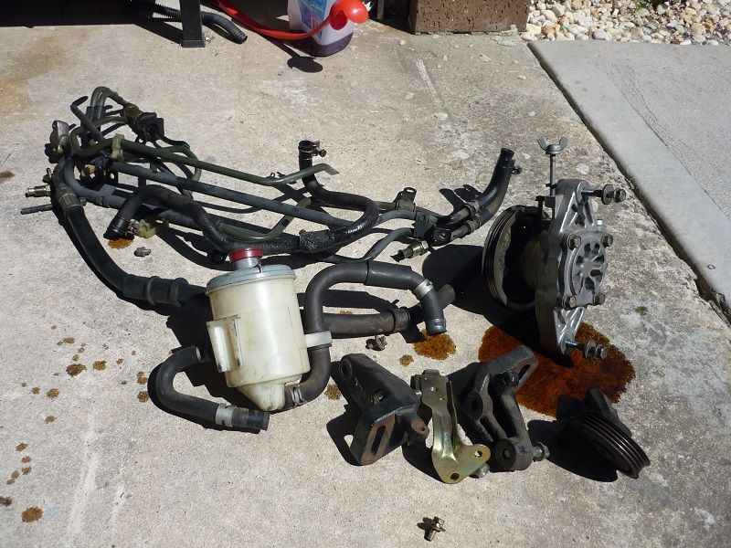
I didn't weigh every thing but i'm sure there has been a net weight reduction
This week I completed the electric power steering pump installation.
I went back to the pick-a-part and collected a second DC2 battery tray, this was then modified to mount the battery in the boot.

This worked out well as it allowed me to re-use the original clamp and the battery is very secure. I will revisit the box sometime in the future, i ended up cutting most of the bottom out of it, so much so that it's not really "Sealed"
Pump in it's final resting place. The pump has it's own mounting bracket which I wanted to re-use so the pump is isolated on its oem rubber mounts. All we did was notch the battery tray to suit the astra bracket and then weld the two together.

Here you can see the relay and circuit breaker mounted off the modified battery tray.

All the auxiliary's have now been removed or replaced off the front of the engine. Regardless of what I end up doing with the engine, not having to worry about power steering is a bonus
The parts that were removed, my driveway is covered in power steering fluid! a warning to anyone thinking of doing this in the future, prepare to get covered in power steering fluid! This would have been much easier with the engine removed.

I didn't weigh every thing but i'm sure there has been a net weight reduction
 11-09-2014, 06:34 PM
#72

Well done on the upgrades, especially the suspension mods. Very well thought out and executed.
I have a question for you on the rear suspension. You mentioned, based on your Susprog data, that the rear roll center moves down and gets worse based on the angle of the rear upper link. Are you certain the rear links have anything to do with the rear roll center location? If you look at the trailing arm where does it pivot? It rotates around the main trailing arm bushing. The rear trailing arm bushing is the roll center location. If you look at some of the aftermarket trailing arm bearing kits, you can see how they try to move them up by offsetting the bushing. This will help correct the rear suspension geometry.
ITR: Fahrwerksbuchsen: Gummi, PU, Kugelgelenke, was ist am besten und warum?
I know, its in German. I have a copy of the book in English, but am not near my scanner yet. I can scan it tomorrow.
Another thing that I have been pondering, the front roll center adjusters are not really helping anything. They don't fix the radical angle of the upper control arm as the car is lowered. This angle changes the rate of the camber gain, should speed it up as the angle gets more and more vertical. I think the only ways to fix the front suspension on a lowered car is to raise both points on the chassis. That means the upper control arm mounts need to go up and the lower arm needs to move up. Lucky for me that is easier on the EF Civic than it is on the ITR.
11-10-2014, 12:09 AM
#73
Honda-Tech Member
Thread Starter
Join Date: Jun 2014
Location: Australia
Posts: 83
Likes: 0
Received 0 Likes
on
0 Posts
Firstly thank you!
I'am 100% sure the rear links dictate the traverse position of the rear roll centre
The angle of the upper control arm is not too bad with 15" wheels and only a minor reduction in ride height.
Another way to reduce the angle of the upper control arm is with a custom upright.
The extended ball joints are beneficial in that they raise the front roll centre and correct for bumpsteer.
Is a higher front roll centre beneficial? Only if the rear has been corrected to suit. IMO of course
11-10-2014, 04:09 AM
#74
Firstly thank you!
I'am 100% sure the rear links dictate the traverse position of the rear roll centre
The angle of the upper control arm is not too bad with 15" wheels and only a minor reduction in ride height.
Another way to reduce the angle of the upper control arm is with a custom upright.
The extended ball joints are beneficial in that they raise the front roll centre and correct for bumpsteer.
Is a higher front roll centre beneficial? Only if the rear has been corrected to suit. IMO of course
I'am 100% sure the rear links dictate the traverse position of the rear roll centre
The angle of the upper control arm is not too bad with 15" wheels and only a minor reduction in ride height.
Another way to reduce the angle of the upper control arm is with a custom upright.
The extended ball joints are beneficial in that they raise the front roll centre and correct for bumpsteer.
Is a higher front roll centre beneficial? Only if the rear has been corrected to suit. IMO of course
(I didn't realize this wasn't in the road race autox forum)
11-10-2014, 11:05 AM
#75
Honda-Tech Member
Thread Starter
Join Date: Jun 2014
Location: Australia
Posts: 83
Likes: 0
Received 0 Likes
on
0 Posts

The roll centre is defined by the intersection of two lines,
the first line is vertical from the cars centre of gravity (simplified as the cars centre line above)
and the second is the line from the tyres contact patch to the instant centre created by suspension geometry
To make it easier to visualize i think of the Honda trailing arm set up as like a double wishbone arrangement except the forward mounting points of the upper and lower wishbones are all at the same point ie the RTA bush.
While this has an impact on the longitudinal position and squat characteristics , when we are speaking about lateral/traverse roll centre and roll moment i believe it is acceptable to treat the geometry as I have done.
Its not about what the trailing arm is doing, it's about the unsprung mass and how the forces generated at the tyre contact patch are reacted on that body